EP0982441A2 - Sanitärer Einhebelmischer - Google Patents
Sanitärer Einhebelmischer Download PDFInfo
- Publication number
- EP0982441A2 EP0982441A2 EP99114395A EP99114395A EP0982441A2 EP 0982441 A2 EP0982441 A2 EP 0982441A2 EP 99114395 A EP99114395 A EP 99114395A EP 99114395 A EP99114395 A EP 99114395A EP 0982441 A2 EP0982441 A2 EP 0982441A2
- Authority
- EP
- European Patent Office
- Prior art keywords
- lever
- mixer
- housing body
- flexible sleeve
- protective cap
- Prior art date
- Legal status (The legal status is an assumption and is not a legal conclusion. Google has not performed a legal analysis and makes no representation as to the accuracy of the status listed.)
- Granted
Links
Images

Classifications
-
- E—FIXED CONSTRUCTIONS
- E03—WATER SUPPLY; SEWERAGE
- E03C—DOMESTIC PLUMBING INSTALLATIONS FOR FRESH WATER OR WASTE WATER; SINKS
- E03C1/00—Domestic plumbing installations for fresh water or waste water; Sinks
- E03C1/02—Plumbing installations for fresh water
- E03C1/04—Water-basin installations specially adapted to wash-basins or baths
- E03C1/0412—Constructional or functional features of the faucet handle
-
- E—FIXED CONSTRUCTIONS
- E03—WATER SUPPLY; SEWERAGE
- E03C—DOMESTIC PLUMBING INSTALLATIONS FOR FRESH WATER OR WASTE WATER; SINKS
- E03C1/00—Domestic plumbing installations for fresh water or waste water; Sinks
- E03C1/02—Plumbing installations for fresh water
- E03C1/04—Water-basin installations specially adapted to wash-basins or baths
Definitions
- the mixer lever can be on the one hand twist about a vertical axis and on the other hand relative to the housing around a horizontal axis tilt. Through these movements of the mixer lever a control unit of the single lever mixer is operated, which adjusts the temperature and the amount of water used.
- the opening must also be accordingly large in the protective cap. It is therefore still relatively easily possible that splashing water through this opening penetrates into the interior of the single-lever mixer. This is undesirable for hygienic reasons and can in extreme cases impair the function of the single lever mixer.
- the additional flexible cuff can be used when moving of the mixer lever carried away by this under deformation be without the possibility of adjusting the mixer lever is affected by it. Therefore, it is no longer necessary the opening through which the fastening section extends the mixer lever and / or the control unit control lever extends to dimension so large that such Contact is avoided.
- the reduced opening of the flexible cuff can in addition, the attachment portion of the mixer lever and / or the control lever of the control unit in the assembled Condition of the single-lever mixer farther above than at Single-lever mixers of the type mentioned in the beginning, surround. This brings a further improvement in protection against splashing water.
- the flexible cuff according to the invention can also be used existing single-lever mixers of the aforementioned Kind of be retrofitted.
- the flexible cuff has multiple sections, an upper section of which when the mixer lever is moving is taken under deformation.
- Such Design leads to the possibility of the individual sections the cuff specifically for certain functions the cuff like elasticity, tightness or the The inclusion of holding devices.
- An advantageous variant of the invention has one Clamping device for holding a lower area one of the sections of the flexible cuff. Thereby becomes a simple and tight attachment of the flexible Protective cap on the housing body enables.
- a further advantageous embodiment of the invention has an area of the entrained section Shape of a hollow cylinder, the longitudinal axis of which is essentially is coaxial with the receiving opening of the housing body.
- the flexible cuff of another embodiment of the Invention has a section whose outer lateral surface form-fitting on an inner surface supports the rigid protective cap. That way the additional rigid protective cap for shaping and support the flexible cuff used. On other means to face the flexible cuff Aligning the mixer lever is not necessary become.
- the flexible cuff of an advantageous embodiment the invention is made of plastic.
- This Material is inexpensive on the one hand and offers on the other hand by deliberately changing the plastic characterizing material parameters the possibility of Function of the flexible cuff vote.
- a such unit also ensures that in sanitary fittings among other things necessary for hygienic reasons Tightness of the housing body. A separate sealing ring is no longer required.
- the flexible cuff and the rigid protective cap of one Another embodiment form a one-piece in multi-component technology manufactured unit.
- Other holding devices are for the flexible cuff in this configuration not required as it is rigid Protective cap is worn.
- the transition area between the flexible cuff and the rigid protective cap splash-proof without further measures.
- the production is also very inexpensive.
- the sections of the flexible cuff itself one piece made of plastic in multi-component technology manufactured unit.
- a sealing area of the flexible cuff with the best possible for this suitable surface a driving area the flexible cuff to be as elastic as possible or an area for holding materials if possible resilient.
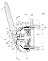
- FIG. 1 shows a single-lever mixer designated 1 overall, in the sanitary area (sink, bathtub, shower) is used.
- the single lever mixer 1 comprises a mixer lever 2, which is used to actuate the control lever 3 serves a cartridge 4 serving as a control unit. In the cartridge 4 takes place depending on the position of the mixer lever 2 the mixing of hot and cold water and the quantity control of the outflowing mixed water.
- the Cartridge 4 is inserted from a receiving opening 30 in 1 shows housing body 5 shown only partially added to which an outlet 32 is formed.
- the mixer lever 2 has a handle part 6 and a arranged above the cartridge 4 mounting portion 7 and a cap area 31, which is the upper end face of the housing body 5 covers.
- a hole 8 of the fastening section 7 is an extension 9 of Adjusting lever 3 inserted, one of the fastening section 7 penetrating grub screw 10, which in a corresponding recess 11 of the extension 9 engages, the extension 9 against slipping out of the Securing section 7 secures.
- a housing 12 of the cartridge 4 has a radial projection 13 on. On the one hand, this serves in the assembled Condition the cartridge housing 12 in the housing body 5, and on the other hand as a system for an in the housing body 5 screwed fastening ring 14th Through the screwed fastening ring 14 is thus the cartridge housing 12 held down in the housing body 5.
- the clamping ring 15 has a circumferential groove, the one Seals ring 33 which rests on the housing body 5 and whose interior seals against splash water.
- the protective cap 16 has approximately the shape of a Hemisphere with a large opening pointing upwards 17.
- the fastening section can be located within this opening 17 7 of the mixer lever 2 when operating the Move the single lever mixer 1 freely without touching the protective cap 16 to come across.
- a sleeve 19 clamped In an annular space between the radially outwardly displaced upper section of the clamping ring 15 and an upper area of the outer lateral surface of the fastening ring 14 is the lower area 18 of a sleeve 19 clamped, which consists of a flexible, preferably consists of elastomeric material.
- This lower one Area 18 of the sleeve 19 has the shape of a hollow cylinder.
- An upper area is in shape on the lower area 18 two dome-shaped sleeve sections 20 and 21 molded.
- the lower sleeve section 20 lies with its outer surface on the inner surface of the Protective cap 16 on.
- an edge 22 of the cuff 19 is formed Edge 22 extends the upper cuff section 21 through the opening 17 of the protective cap 16 with initially constant, then dome-like upwards tapering cross section.
- the longitudinal axis of the hollow cylindrical transition area of the upper cuff section 21 above the edge 22 is coaxial with the mounting section 7.
- the upper Completion of the upper sleeve portion 21 and thus the entire cuff 19 forms an opening 23 which the Fastening section 7 of the mixer lever 2 with relatively small distance surrounds.
- a tool for actuating the grub screw 10 To be able to insert is below the handle part 6 of the Mixer lever 2 in the housing body 5 facing Cap region 31, a through hole 24 is provided. Through this through hole 24, the grub screw 11 can be achieved. There is also an edge recess 25 in the upper edge region adjacent to the opening 17 Protective cap 16 necessary, its position with the longitudinal axis the grub screw 11 is aligned. The shape and position of the Recess 25 is also illustrated by FIG. 2.
- the single-lever mixer 1 is a plan view shown with the mixer lever 2 removed.
- the mixer lever 2 When moving the mixer lever 2 in to reach the required amount and temperature of water
- the mixer lever 2 can be positioned from the position shown in FIG shown center position, in which the lever 3 is substantially vertical, twisted and into one Position tilted, at which the adjusting lever 3 is inclined is posed.
- the opening 17 of the rigid protective cap 16 must therefore be so large that the fastening section 7 (see FIG. 1) within the range of movement of the Mixer lever 2 does not hit the protective cap 16.
- the opening 23 in the upper sleeve portion 21 of the Cuff 19, however, can be much smaller than that Opening 17 to be executed and even at the limit the outer lateral surface of the fastening section 7 apply (not shown in Figure 1).
- the mixer lever 2 takes the area of the outer surface the fastening section 7 of the mixer lever 2, which is moved towards an edge region of the opening 23, the flexible sleeve portion 21 under elastic Deformation with when the fastening section 7th is tilted further than the play of the opening 23 allowed.
- a defined deformation of the sleeve 19 during a Movement of the mixer lever 2 achieved that essentially tilting of the cuff section 21 corresponds to the cuff section 20.
- the flexible shown in one piece in the drawing Cuff 19 can by means of multi-component spray technology in one piece with the then also made of plastic rigid protective cap 16 may be connected.
- the protective cap 16 consists of one by corresponding Additives produced rigid plastic during the cuff 19 according to their sealing and deformation function consists of a flexible plastic mixture.
- the cuff 19 can also be made of different flexible Cuff sections exist, which are also by means of Multi-component spray technology can be produced.
- the cuff section 18 consists of a harder plastic compound to get yourself in the clamping not too deformed by the clamping ring 15.
- the cuff section 20 is designed such that he with its outer surface as well as possible on the inner surface the rigid protective cap 16 seals.
- the plastic mixture in the area of the edge 22 is against wear at the Deformation of the sleeve 19 optimized.
- the cuff section 21 is finally designed so flexible that he has a driving movement of the fastening section 7 opposes the lowest possible forces.
Landscapes
- Health & Medical Sciences (AREA)
- Life Sciences & Earth Sciences (AREA)
- Engineering & Computer Science (AREA)
- Hydrology & Water Resources (AREA)
- Public Health (AREA)
- Water Supply & Treatment (AREA)
- Domestic Plumbing Installations (AREA)
- Mixers Of The Rotary Stirring Type (AREA)
- Multiple-Way Valves (AREA)
- Food-Manufacturing Devices (AREA)
- Confectionery (AREA)
- Footwear And Its Accessory, Manufacturing Method And Apparatuses (AREA)
Abstract
Description
- Figur 1:
- eine geschnittene Teilansicht eines Einhebelmischers; und
- Figur 2:
- eine Draufsicht des Einhebelmischers von Figur 1 mit abgenommenem Mischerhebel.
Claims (9)
- Sanitärer Einhebelmischer mita) einem Gehäusekörper, der eine zu seiner oberen Stirnseite hin offene Aufnahmeöffnung aufweist;b) einer in der Aufnahmeöffnung des Gehäusekörpers angeordneten Steuereinheit, deren Stellhebel nach oben ragt;c) einem über der oberen Stirnseite des Gehäusekörpers angeordneten Mischerhebel, der einen mit dem Stellhebel verbundenen Befestigungsabschnitt aufweist;d) einer unterhalb des Mischerhebels angeordneten starren Schutzkappe, welche die Aufnahmeöffnung des Gehäusekörpers nach oben abdeckt und eine Öffnung aufweist, durch welche sich der Befestigungsabschnitt des Mischerhebels und/oder der Stellhebel der Steuereinheit hindurch erstreckt,
dadurch gekennzeichnet, daße) die Öffnung (17) der starren Schutzkappe (16) durch eine flexible Manschette (19) verkleinert ist, die eine kleinere Öffnung (23) aufweist, durch welche sich der Befestigungsabschnitt (7) des Mischerhebels (2) und/oder der Stellhebel (3) der Steuereinheit (4) hindurch erstreckt. - Sanitärer Einhebelmischer nach Anspruch 1, dadurch
gekennzeichnet, daß die flexible Manschette (19) mehrere Abschnitte (18, 20, 21) aufweist, von denen ein oberer Abschnitt (21) bei der Bewegung des Mischerhebels (2) unter Verformung mitgenommen wird. - Sanitärer Einhebelmischer nach Anspruch 1 oder 2,
gekennzeichnet durch eine Klemmvorrichtung (14, 15) zur Halterung eines unteren Bereichs eines der Abschnitte (18) der flexiblen Manschette (19). - Sanitärer Einhebelmischer nach einem der vorhergehenden
Ansprüche dadurch gekennzeichnet, daß ein Bereich des mitgenommenen Abschnitts (21) die Form eines Hohlzylinders hat, dessen Längsachse im wesentlichen koaxial zur Aufnahmeöffnung (30) des Gehäusekörpers (5) ist. - Sanitärer Einhebelmischer nach einem der vorhergehenden
Ansprüche, dadurch gekennzeichnet, daß die flexible Manschette (19) einen Abschnitt (20) aufweist, dessen äußere Mantelfläche sich formschlüssig an einer inneren Mantelfläche der starren Schutzkappe (16) abstützt. - Sanitärer Einhebelmischer nach einem der vorhergehenden
Ansprüche, dadurch gekennzeichnet, daß die flexible Manschette (19) aus Kunststoff hergestellt ist. - Sanitärer Einhebelmischer nach Anspruch 6, dadurch
gekennzeichnet, daß die flexible Manschette (19), ein Ring (15), mit dem die flexible Manschette (19) an dem Gehäusekörper (5) befestigt ist, sowie eine den Gehäusekörper (5) nach innen abdichtende Dichtung (33) eine einstückig in Mehrkomponenten-Technik gefertigte Einheit bilden. - Sanitärer Einhebelmischer nach Anspruch 6 oder 7,
dadurch gekennzeichnet, daß die flexible Manschette (19) und die starre Schutzkappe (16) eine einstückig in Mehrkomponenten-Technik gefertigte Einheit bilden. - Sanitärer Einhebelmischer nach einem der Ansprüche 6
bis 8, dadurch gekennzeichnet, daß die Abschnitte (18, 20, 21) der flexiblen Manschette (19) eine einstückig in Mehrkomponenten-Technik gefertigte Einheit bilden.
Applications Claiming Priority (2)
| Application Number | Priority Date | Filing Date | Title |
|---|---|---|---|
| DE19837966A DE19837966C2 (de) | 1998-08-21 | 1998-08-21 | Sanitärer Einhebelmischer |
| DE19837966 | 1998-08-21 |
Publications (3)
| Publication Number | Publication Date |
|---|---|
| EP0982441A2 true EP0982441A2 (de) | 2000-03-01 |
| EP0982441A3 EP0982441A3 (de) | 2001-04-04 |
| EP0982441B1 EP0982441B1 (de) | 2006-12-27 |
Family
ID=7878250
Family Applications (1)
| Application Number | Title | Priority Date | Filing Date |
|---|---|---|---|
| EP99114395A Expired - Lifetime EP0982441B1 (de) | 1998-08-21 | 1999-07-22 | Sanitärer Einhebelmischer |
Country Status (5)
| Country | Link |
|---|---|
| EP (1) | EP0982441B1 (de) |
| AT (1) | ATE349580T1 (de) |
| CZ (1) | CZ293587B6 (de) |
| DE (2) | DE19837966C2 (de) |
| ES (1) | ES2278426T3 (de) |
Cited By (3)
| Publication number | Priority date | Publication date | Assignee | Title |
|---|---|---|---|---|
| DE102005040160A1 (de) * | 2005-08-25 | 2007-03-01 | Hansa Metallwerke Ag | Sanitärer Einhebelmischer |
| EP2489792A1 (de) * | 2011-02-16 | 2012-08-22 | Kwc Ag | Sanitärarmatur mit einem Abdeckelement zum Schutz einer Steuerpatrone |
| US20150247587A1 (en) * | 2012-09-24 | 2015-09-03 | Ergonomix Concept E.G Ltd | Nonlinear transmission rate between operating handle and operated mechanism |
Families Citing this family (1)
| Publication number | Priority date | Publication date | Assignee | Title |
|---|---|---|---|---|
| DE102011083448B4 (de) * | 2011-09-26 | 2014-11-27 | Hansgrohe Se | Sanitärarmatur |
Family Cites Families (4)
| Publication number | Priority date | Publication date | Assignee | Title |
|---|---|---|---|---|
| DE2757525A1 (de) * | 1977-12-23 | 1979-07-05 | Hansa Metallwerke Ag | Steuerscheiben-mischventil |
| DE3120171A1 (de) * | 1981-05-21 | 1983-01-05 | Friedrich Grohe Armaturenfabrik Gmbh & Co, 5870 Hemer | Handhebel fuer eingriffmischventil mit stellungsanzeige |
| DE3546504A1 (de) * | 1985-07-13 | 1987-03-19 | Ideal Standard | Sanitaere mischbatterie |
| DE4421983C2 (de) * | 1994-06-23 | 1998-04-09 | Meloh Armaturen Ruppel & Meloh | Sanitär-Armatur |
-
1998
- 1998-08-21 DE DE19837966A patent/DE19837966C2/de not_active Expired - Fee Related
-
1999
- 1999-07-22 ES ES99114395T patent/ES2278426T3/es not_active Expired - Lifetime
- 1999-07-22 DE DE59914086T patent/DE59914086D1/de not_active Expired - Lifetime
- 1999-07-22 EP EP99114395A patent/EP0982441B1/de not_active Expired - Lifetime
- 1999-07-22 AT AT99114395T patent/ATE349580T1/de active
- 1999-08-17 CZ CZ19992917A patent/CZ293587B6/cs not_active IP Right Cessation
Cited By (8)
| Publication number | Priority date | Publication date | Assignee | Title |
|---|---|---|---|---|
| DE102005040160A1 (de) * | 2005-08-25 | 2007-03-01 | Hansa Metallwerke Ag | Sanitärer Einhebelmischer |
| US7900649B2 (en) | 2005-08-25 | 2011-03-08 | Hansa Metallwerke Ag | Sanitary single-lever mixer |
| EP2489792A1 (de) * | 2011-02-16 | 2012-08-22 | Kwc Ag | Sanitärarmatur mit einem Abdeckelement zum Schutz einer Steuerpatrone |
| CN102644756A (zh) * | 2011-02-16 | 2012-08-22 | Kwc股份公司 | 包含用于保护控制筒的覆盖元件的卫生设备 |
| CH704504A1 (de) * | 2011-02-16 | 2012-08-31 | Kwc Ag | Sanitärarmatur mit einem Abdeckelement zum Schutz einer Steuerpatrone. |
| CN102644756B (zh) * | 2011-02-16 | 2016-03-02 | 弗兰肯水系统股份公司 | 包含用于保护控制筒的覆盖元件的卫生设备 |
| US20150247587A1 (en) * | 2012-09-24 | 2015-09-03 | Ergonomix Concept E.G Ltd | Nonlinear transmission rate between operating handle and operated mechanism |
| US9841121B2 (en) * | 2012-09-24 | 2017-12-12 | Eran Ben-Dor | Nonlinear transmission rate between operating handle and operated mechanism |
Also Published As
| Publication number | Publication date |
|---|---|
| ES2278426T3 (es) | 2007-08-01 |
| ATE349580T1 (de) | 2007-01-15 |
| CZ293587B6 (cs) | 2004-06-16 |
| DE19837966A1 (de) | 2000-04-06 |
| DE59914086D1 (de) | 2007-02-08 |
| CZ9902917A3 (cs) | 2001-04-11 |
| EP0982441A3 (de) | 2001-04-04 |
| EP0982441B1 (de) | 2006-12-27 |
| DE19837966C2 (de) | 2003-04-24 |
Similar Documents
| Publication | Publication Date | Title |
|---|---|---|
| DE2320624C2 (de) | Umschaltbarer Strahlregler | |
| EP0592629B1 (de) | Zentraldichtstiftverschluss | |
| CH623904A5 (de) | ||
| CH691936A5 (de) | Betätigungsmittel mit Dichtung für eine Uhr. | |
| DE202019104774U1 (de) | Neuartige messerschalterartige Vier-Wege-Wasserdurchlassstruktur | |
| DE2234248A1 (de) | Wasserspender fuer tiere | |
| DE2926374A1 (de) | Langsam schliessender wasserhahn | |
| DE29713238U1 (de) | Wasserleitungsarmatur | |
| DE2238061B2 (de) | Bohrwerkzeug für kleine Durchmesser | |
| DE2417376A1 (de) | Mischventil | |
| DE10146277A1 (de) | Wasserarmatur | |
| AT393155B (de) | Sanitaeres ventil | |
| WO2005068884A1 (de) | Sanitärarmatur | |
| EP2203667A1 (de) | Sitzreinigungsfähiges doppelsitzventil und verfahren zur reinigung des sitzreinigungsfähigen doppelsitzventils | |
| EP0982441B1 (de) | Sanitärer Einhebelmischer | |
| DE2407933A1 (de) | Umleitventil fuer brausen-wannenarmaturen | |
| EP0271771B1 (de) | Heisswasserventil | |
| DE2936079A1 (de) | Umschaltventil | |
| DE2264815A1 (de) | Mischbatterie | |
| WO2015117767A1 (de) | Armatur mit einem schwenkauslauf | |
| DE20000703U1 (de) | Universalverschluß zum Verschließen von geöffneten Flaschen, insbesondere für Schaumwein- und Weinflaschen | |
| EP1333342B1 (de) | Betätigungsmittel mit Dichtung für eine Uhr | |
| DE2907565C2 (de) | Kombinierte Selbstschluß- und Mischarmatur | |
| DE2737478B2 (de) | Einhebelmischbatterie | |
| DE2324364A1 (de) | Einhand-mischbatterie |
Legal Events
| Date | Code | Title | Description |
|---|---|---|---|
| PUAI | Public reference made under article 153(3) epc to a published international application that has entered the european phase |
Free format text: ORIGINAL CODE: 0009012 |
|
| AK | Designated contracting states |
Kind code of ref document: A2 Designated state(s): AT BE CH CY DE DK ES FI FR GB GR IE IT LI LU MC NL PT SE |
|
| AX | Request for extension of the european patent |
Free format text: AL;LT;LV;MK;RO;SI |
|
| PUAL | Search report despatched |
Free format text: ORIGINAL CODE: 0009013 |
|
| AK | Designated contracting states |
Kind code of ref document: A3 Designated state(s): AT BE CH CY DE DK ES FI FR GB GR IE IT LI LU MC NL PT SE |
|
| AX | Request for extension of the european patent |
Free format text: AL;LT;LV;MK;RO;SI |
|
| 17P | Request for examination filed |
Effective date: 20010508 |
|
| AKX | Designation fees paid |
Free format text: AT BE CH CY DE DK ES FI FR GB GR IE IT LI LU MC NL PT SE |
|
| 17Q | First examination report despatched |
Effective date: 20040213 |
|
| GRAP | Despatch of communication of intention to grant a patent |
Free format text: ORIGINAL CODE: EPIDOSNIGR1 |
|
| GRAS | Grant fee paid |
Free format text: ORIGINAL CODE: EPIDOSNIGR3 |
|
| GRAA | (expected) grant |
Free format text: ORIGINAL CODE: 0009210 |
|
| AK | Designated contracting states |
Kind code of ref document: B1 Designated state(s): AT BE CH CY DE DK ES FI FR GB GR IE IT LI LU MC NL PT SE |
|
| PG25 | Lapsed in a contracting state [announced via postgrant information from national office to epo] |
Ref country code: IE Free format text: LAPSE BECAUSE OF FAILURE TO SUBMIT A TRANSLATION OF THE DESCRIPTION OR TO PAY THE FEE WITHIN THE PRESCRIBED TIME-LIMIT Effective date: 20061227 Ref country code: FI Free format text: LAPSE BECAUSE OF FAILURE TO SUBMIT A TRANSLATION OF THE DESCRIPTION OR TO PAY THE FEE WITHIN THE PRESCRIBED TIME-LIMIT Effective date: 20061227 Ref country code: DK Free format text: LAPSE BECAUSE OF FAILURE TO SUBMIT A TRANSLATION OF THE DESCRIPTION OR TO PAY THE FEE WITHIN THE PRESCRIBED TIME-LIMIT Effective date: 20061227 |
|
| REG | Reference to a national code |
Ref country code: GB Ref legal event code: FG4D Free format text: NOT ENGLISH |
|
| GBT | Gb: translation of ep patent filed (gb section 77(6)(a)/1977) |
Effective date: 20061228 |
|
| REG | Reference to a national code |
Ref country code: IE Ref legal event code: FG4D Free format text: LANGUAGE OF EP DOCUMENT: GERMAN |
|
| REF | Corresponds to: |
Ref document number: 59914086 Country of ref document: DE Date of ref document: 20070208 Kind code of ref document: P |
|
| REG | Reference to a national code |
Ref country code: CH Ref legal event code: NV Representative=s name: FREI PATENTANWALTSBUERO |
|
| PG25 | Lapsed in a contracting state [announced via postgrant information from national office to epo] |
Ref country code: SE Free format text: LAPSE BECAUSE OF FAILURE TO SUBMIT A TRANSLATION OF THE DESCRIPTION OR TO PAY THE FEE WITHIN THE PRESCRIBED TIME-LIMIT Effective date: 20070327 |
|
| PG25 | Lapsed in a contracting state [announced via postgrant information from national office to epo] |
Ref country code: PT Free format text: LAPSE BECAUSE OF FAILURE TO SUBMIT A TRANSLATION OF THE DESCRIPTION OR TO PAY THE FEE WITHIN THE PRESCRIBED TIME-LIMIT Effective date: 20070528 |
|
| ET | Fr: translation filed | ||
| REG | Reference to a national code |
Ref country code: ES Ref legal event code: FG2A Ref document number: 2278426 Country of ref document: ES Kind code of ref document: T3 |
|
| PLBE | No opposition filed within time limit |
Free format text: ORIGINAL CODE: 0009261 |
|
| STAA | Information on the status of an ep patent application or granted ep patent |
Free format text: STATUS: NO OPPOSITION FILED WITHIN TIME LIMIT |
|
| 26N | No opposition filed |
Effective date: 20070928 |
|
| PG25 | Lapsed in a contracting state [announced via postgrant information from national office to epo] |
Ref country code: MC Free format text: LAPSE BECAUSE OF NON-PAYMENT OF DUE FEES Effective date: 20070731 Ref country code: GR Free format text: LAPSE BECAUSE OF FAILURE TO SUBMIT A TRANSLATION OF THE DESCRIPTION OR TO PAY THE FEE WITHIN THE PRESCRIBED TIME-LIMIT Effective date: 20070328 |
|
| PG25 | Lapsed in a contracting state [announced via postgrant information from national office to epo] |
Ref country code: LU Free format text: LAPSE BECAUSE OF NON-PAYMENT OF DUE FEES Effective date: 20070722 Ref country code: CY Free format text: LAPSE BECAUSE OF FAILURE TO SUBMIT A TRANSLATION OF THE DESCRIPTION OR TO PAY THE FEE WITHIN THE PRESCRIBED TIME-LIMIT Effective date: 20061227 |
|
| PGFP | Annual fee paid to national office [announced via postgrant information from national office to epo] |
Ref country code: FR Payment date: 20110729 Year of fee payment: 13 Ref country code: CH Payment date: 20110720 Year of fee payment: 13 |
|
| PGFP | Annual fee paid to national office [announced via postgrant information from national office to epo] |
Ref country code: AT Payment date: 20110727 Year of fee payment: 13 Ref country code: GB Payment date: 20110720 Year of fee payment: 13 Ref country code: DE Payment date: 20110927 Year of fee payment: 13 Ref country code: ES Payment date: 20110726 Year of fee payment: 13 |
|
| PGFP | Annual fee paid to national office [announced via postgrant information from national office to epo] |
Ref country code: NL Payment date: 20110722 Year of fee payment: 13 Ref country code: BE Payment date: 20110805 Year of fee payment: 13 Ref country code: IT Payment date: 20110728 Year of fee payment: 13 |
|
| BERE | Be: lapsed |
Owner name: HANSA METALLWERKE A.G. Effective date: 20120731 |
|
| REG | Reference to a national code |
Ref country code: NL Ref legal event code: V1 Effective date: 20130201 |
|
| REG | Reference to a national code |
Ref country code: CH Ref legal event code: PL |
|
| REG | Reference to a national code |
Ref country code: AT Ref legal event code: MM01 Ref document number: 349580 Country of ref document: AT Kind code of ref document: T Effective date: 20120722 |
|
| GBPC | Gb: european patent ceased through non-payment of renewal fee |
Effective date: 20120722 |
|
| REG | Reference to a national code |
Ref country code: FR Ref legal event code: ST Effective date: 20130329 |
|
| PG25 | Lapsed in a contracting state [announced via postgrant information from national office to epo] |
Ref country code: LI Free format text: LAPSE BECAUSE OF NON-PAYMENT OF DUE FEES Effective date: 20120731 Ref country code: CH Free format text: LAPSE BECAUSE OF NON-PAYMENT OF DUE FEES Effective date: 20120731 Ref country code: FR Free format text: LAPSE BECAUSE OF NON-PAYMENT OF DUE FEES Effective date: 20120731 Ref country code: DE Free format text: LAPSE BECAUSE OF NON-PAYMENT OF DUE FEES Effective date: 20130201 Ref country code: NL Free format text: LAPSE BECAUSE OF NON-PAYMENT OF DUE FEES Effective date: 20130201 Ref country code: GB Free format text: LAPSE BECAUSE OF NON-PAYMENT OF DUE FEES Effective date: 20120722 |
|
| PG25 | Lapsed in a contracting state [announced via postgrant information from national office to epo] |
Ref country code: BE Free format text: LAPSE BECAUSE OF NON-PAYMENT OF DUE FEES Effective date: 20120731 Ref country code: IT Free format text: LAPSE BECAUSE OF NON-PAYMENT OF DUE FEES Effective date: 20120722 |
|
| PG25 | Lapsed in a contracting state [announced via postgrant information from national office to epo] |
Ref country code: AT Free format text: LAPSE BECAUSE OF NON-PAYMENT OF DUE FEES Effective date: 20120722 |
|
| REG | Reference to a national code |
Ref country code: DE Ref legal event code: R119 Ref document number: 59914086 Country of ref document: DE Effective date: 20130201 |
|
| REG | Reference to a national code |
Ref country code: ES Ref legal event code: FD2A Effective date: 20131022 |
|
| PG25 | Lapsed in a contracting state [announced via postgrant information from national office to epo] |
Ref country code: ES Free format text: LAPSE BECAUSE OF NON-PAYMENT OF DUE FEES Effective date: 20120723 |