EP0982446A1 - Agencement de panneaux d'accès pour faux plafond ou cloison pare-feu - Google Patents
Agencement de panneaux d'accès pour faux plafond ou cloison pare-feu Download PDFInfo
- Publication number
- EP0982446A1 EP0982446A1 EP99305566A EP99305566A EP0982446A1 EP 0982446 A1 EP0982446 A1 EP 0982446A1 EP 99305566 A EP99305566 A EP 99305566A EP 99305566 A EP99305566 A EP 99305566A EP 0982446 A1 EP0982446 A1 EP 0982446A1
- Authority
- EP
- European Patent Office
- Prior art keywords
- access panel
- firewall
- false ceiling
- access
- pins
- Prior art date
- Legal status (The legal status is an assumption and is not a legal conclusion. Google has not performed a legal analysis and makes no representation as to the accuracy of the status listed.)
- Withdrawn
Links
- 239000011800 void material Substances 0.000 claims description 10
- 229910000831 Steel Inorganic materials 0.000 claims 2
- 239000010959 steel Substances 0.000 claims 2
- 239000002184 metal Substances 0.000 description 5
- 230000005484 gravity Effects 0.000 description 2
- 238000007493 shaping process Methods 0.000 description 2
- 238000003466 welding Methods 0.000 description 2
- 238000005253 cladding Methods 0.000 description 1
- 238000009434 installation Methods 0.000 description 1
- 230000000750 progressive effect Effects 0.000 description 1
- 230000000717 retained effect Effects 0.000 description 1
- 239000000725 suspension Substances 0.000 description 1
- XLYOFNOQVPJJNP-UHFFFAOYSA-N water Substances O XLYOFNOQVPJJNP-UHFFFAOYSA-N 0.000 description 1
Images


Classifications
-
- E—FIXED CONSTRUCTIONS
- E05—LOCKS; KEYS; WINDOW OR DOOR FITTINGS; SAFES
- E05D—HINGES OR SUSPENSION DEVICES FOR DOORS, WINDOWS OR WINGS
- E05D3/00—Hinges with pins
- E05D3/06—Hinges with pins with two or more pins
- E05D3/12—Hinges with pins with two or more pins with two parallel pins and one arm
-
- E—FIXED CONSTRUCTIONS
- E04—BUILDING
- E04B—GENERAL BUILDING CONSTRUCTIONS; WALLS, e.g. PARTITIONS; ROOFS; FLOORS; CEILINGS; INSULATION OR OTHER PROTECTION OF BUILDINGS
- E04B9/00—Ceilings; Construction of ceilings, e.g. false ceilings; Ceiling construction with regard to insulation
- E04B9/003—Ceilings; Construction of ceilings, e.g. false ceilings; Ceiling construction with regard to insulation with movable parts, e.g. pivoting panels, access doors
-
- E—FIXED CONSTRUCTIONS
- E04—BUILDING
- E04F—FINISHING WORK ON BUILDINGS, e.g. STAIRS, FLOORS
- E04F19/00—Other details of constructional parts for finishing work on buildings
- E04F19/08—Built-in cupboards; Masks of niches; Covers of holes enabling access to installations
-
- E—FIXED CONSTRUCTIONS
- E05—LOCKS; KEYS; WINDOW OR DOOR FITTINGS; SAFES
- E05D—HINGES OR SUSPENSION DEVICES FOR DOORS, WINDOWS OR WINGS
- E05D3/00—Hinges with pins
- E05D3/06—Hinges with pins with two or more pins
- E05D3/18—Hinges with pins with two or more pins with sliding pins or guides
-
- E—FIXED CONSTRUCTIONS
- E05—LOCKS; KEYS; WINDOW OR DOOR FITTINGS; SAFES
- E05Y—INDEXING SCHEME ASSOCIATED WITH SUBCLASSES E05D AND E05F, RELATING TO CONSTRUCTION ELEMENTS, ELECTRIC CONTROL, POWER SUPPLY, POWER SIGNAL OR TRANSMISSION, USER INTERFACES, MOUNTING OR COUPLING, DETAILS, ACCESSORIES, AUXILIARY OPERATIONS NOT OTHERWISE PROVIDED FOR, APPLICATION THEREOF
- E05Y2900/00—Application of doors, windows, wings or fittings thereof
- E05Y2900/10—Application of doors, windows, wings or fittings thereof for buildings or parts thereof
- E05Y2900/13—Type of wing
- E05Y2900/131—Access panels
Definitions
- the invention relates to suspended false ceilings or firewalls, and to the mounting of access panels as part of the false ceiling or firewall structure, to allow access to the void space immediately above the false ceiling or immediately behind the firewall.
- the invention provides a novel hinge arrangement for mounting such access panels, and to the access panels when so mounted.
- a suspended false ceiling typically comprises a metal framework suspended beneath the true ceiling, with ceiling panels supported by that framework to present a uniform and level ceiling appearance when viewed from the room below. Access is almost invariably required to the void space above the suspended ceiling, where the main service utilities such as electric cables, water pipes and air ducts are located.
- the access panels are generally pivotally mounted to the false ceiling framework, and can be lowered to permit access to the void space above the false ceiling.
- there is generally a void area behind the firewall where the main service utilities are provided, and access openings are needed to permit access to those utilities.
- the hinge is a simple continuous piano hinge aligned with its hinge axis in the plane of the bottom of the ceiling or in the plane of the exposed face of the firewall, so that as the access panel is opened it pivots around its bottom corner.
- Such a hinge arrangement is cheap and reliable, but does have the very severe disadvantage that the edge of the hinge is always clearly visible from the room, as a hinge line projecting from the exposed face of the false ceiling or firewall. This is regarded as extremely undesirable, since architects and end users prefer a finished suspended ceiling or firewall which has a completely uniform appearance, with the access panels being as far as possible indistinguishable from the remainder of the suspended ceiling or firewall. Many efforts have been made, therefore, to recess the pivotal axis of the false ceiling or firewall access panel until it is no longer visible from the room. This involves a more complex movement of the access panel than simple pivotal movement as it is opened and closed.
- the invention provides an access panel for allowing access to a void space beyond a false ceiling or firewall, comprising a front face which in use lies flush with the exposed face of the false ceiling or firewall and a rear face displaced from the front face by the thickness of the access panel; and a mounting assembly for mounting the access panel on the false ceiling or firewall for pivotal movement generally about a pair of pins extending from opposite sides of the access panel and adjacent a pivoting edge portion thereof, each pin traversing an associated cam guide slot in the supporting framework of the false ceiling of firewall during the pivotal opening and closing movement of the access panel; wherein the mounting assembly further comprises a double axis hinge comprising a support plate fast to or integral with the rear face of the access panel; a guide plate pivotally connected to the support plate about a first hinge axis coincident with or parallel to the rear face of the access panel; and a mounting plate pivotally connected to the guide plate about a second hinge axis spaced from and parallel to the first hinge axis, the mounting plate being provided with means for connection to an
- the invention also provides a false ceiling or firewall access panel assembly, in which a false ceiling or firewall access panel according to the invention is mounted to the frame of a false ceiling or firewall to be movable pivotally to open or close an access opening.
- the guide plate of the hinge assembly holds the access panel square to the frame of the access opening and forces the pins to traverse the cam guide slot to ensure that the bottom corner edge of the access panel moves in a controlled path without swinging into and fouling the corresponding edge of the frame of the access opening.
- the guide plate may be a simple flat plate connecting the two pivotal axes of the double axis hinge, in which case the first hinge axis should be along the rear pivoting edge of the access panel.
- the guide plate is shaped to allow the first hinge axis to be displaced inwardly from the rear pivoting edge of the access panel.
- the shaping of the guide plate in this way makes it possible to provide a positive stop to the maximum pivotal opening movement of the access panel by inter-engagement between the guide plate and the rear surface of the access panel. Such a positive stop prevents fouling of the front face of the access panel against the supporting framework of the false ceiling or firewall by movement of the access panel beyond its intended maximum range of opening movement.
- a suspended false ceiling indicated generally as 1 comprising an array of ceiling tiles 2 supported by a suspended grid of supporting rails 3.
- the suspension of the grid is by any conventional means.
- Figure 1 shows three of the ceiling tiles 2 removed, so as to permit sight of the rails 3 of the grid, and to permit sight of the void space 4 above the false ceiling.
- FIG. 1 Also illustrated in Figure 1 is an access panel 5 for allowing access to the void space above the false ceiling.
- the access panel 5 is shown partially open, and a double-headed arrow 6 illustrates the opening and closing movement of the access panel 5 which is a generally pivotal movement around one pivoting edge portion 7 of the access panel 5.
- One corner of the pivotal edge portion 7 is encircled and marked A , and it is that corner which is shown in greater detail in Figures 2 to 8.
- FIGS 2 to 8 illustrate the pivotal mounting of the access panel 5.
- the access panel 5 comprises a metal top plate 8 which is the size of the access opening and a bottom face 9 which, when the access panel 5 is closed, lies flush with the remainder of the suspended ceiling 1. Since the terms 'top' and 'bottom' are specific to false ceilings whereas this invention is generic to false ceilings and firewalls, the metal plate 8 will hereafter be referred to as the rear plate 8, and the opposite face 9 will be referred to as the front face 9. It is the front faces of the false ceiling or firewall and of the access panel 5 which are visible from the room.
- the front face 9 of the access panel 5 is a metal plate. It should be understood however that any suitable cladding may be supported by the access panel 5, typically one or more acoustic tiles.
- the pivoting edge portion 7 of the access panel 5 has one exposed corner 10 which must be protected by preventing it from fouling the corresponding edge of the frame 3 of the access opening. This is achieved according to the invention by means of a double axis hinge assembly 11 in association with pins 13 received in associated cam guide slots 12 which will be described in greater detail below.
- the double axis hinge assembly 11 comprises a support plate 14 which in use is secured to the rear face of the metal plate 8, for example by spot-welding, by bolts or by rivets.
- the support plate 14 defines a first hinge axis 15 which in use is parallel to and in this embodiment displaced slightly inwardly from the exposed corner 10 of the pivoting edge portion 7 of the access panel 5 when the access panel 5 is in its closed condition.
- Hinged to the support plate and thus to the top face of the access panel along that pivoting edge portion 7 is a guide plate 16 which is kinked or angled as illustrated by means of a longitudinal fold 16' parallel to the first hinge axis 15. The reason for this shaping of the guide plate 16 will become apparent later.
- the longitudinal edge of the guide plate 16 remote from the first hinge axis 15 defines a second hinge axis 17 spaced from and parallel to the first hinge axis 15.
- a mounting plate 18 is hinged to the guide plate 16 about the second hinge axis 17.
- the mounting plate 18 is secured fast to the supporting rail 3 which defines one edge of the access opening, for example by spot welding, by bolts or by rivets (not shown).
- the double axis hinge 11 is preferably a continuous hinge extending substantially the entire width of the access panel 5.
- a linear array of two or more discrete hinges 11 could be provided, spaced apart along the width of the access panel 5, provided that their respective hinge axes 15 and 17 are in mutual alignment.
- mounting brackets 19 At opposite ends of the hinge 11 or of the array of hinges 11 are mounting brackets 19 as shown in Figure 8, each of which carries a laterally projecting pin 13 about which pivotal movement of the access panel 5 takes place during opening and closing.
- the pins 13 are received in cam guide slots 12 formed as illustrated in the side walls 3 of the access opening or in plates (not illustrated) secured to those side walls 3.
- the cam guide slots 12 are enclosed slots in which the pins 13 move, and the shape of the slots is variable.
- the slots 12 are inclined downwardly in the general direction from the pivoting edge portion 7 towards the opening edge of the access panel 5 as shown, so that the weight of the access panel assists in moving the pins 13 along and down the slots 12 as the panel 5 is moved from the closed to the open condition (see Figures 2 to 7).
- the slots 12 may be linear as shown or non-linear. What is most important about the shapes of the slots 12 is that they must extend away from the pivoting edge portion 7 of the access panel 5 and away from the exposed corner 10, so that as the panel is moved from a closed condition ( Figure 2)) to an open condition ( Figure 7) the pins 13 move laterally in the slots 12 and draw the pivoting edge portion 7 of the access panel 5 away from the corresponding edge of the access opening.
- the front face or exposed corner 10 of the access panel 5 thus does not foul the supporting framework 3 of the false ceiling.
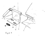
- the mounting brackets 19 are retained by screws 20 received in the rear face of the access panel 5, with slots 21 allowing adjustment in the direction of the double-headed arrow B to permit assembly.
- the double axis hinge 11 forces the pins 13 to perform the necessary traverse of the slots 12, and also prevents yawing of the access panel 5.
- Figures 2 to 7 illustrate the sequential stages of movement. Pivotal movement of the panel 5 at all stages is about the pins 13, but as the panel pivots the pins 13 are forced to move longitudinally along the slots 12. The maximum traverse of the pins 13 down or along the slots 12 is when the axis of the pins 13, the first hinge axis 15 and the second hinge axis 17 are in a straight line (at the stage of opening shortly after that of Figure 6) and after that the pins move slightly back along the slots 12.
- cam tracks 12 are enclosed double-sided slots, the panel closing movement is controlled in an entirely analogous manner.
Landscapes
- Engineering & Computer Science (AREA)
- Architecture (AREA)
- Civil Engineering (AREA)
- Structural Engineering (AREA)
- Mechanical Engineering (AREA)
- Physics & Mathematics (AREA)
- Electromagnetism (AREA)
- Hinges (AREA)
Priority Applications (1)
| Application Number | Priority Date | Filing Date | Title |
|---|---|---|---|
| EP99305566A EP0982446A1 (fr) | 1998-08-21 | 1999-07-14 | Agencement de panneaux d'accès pour faux plafond ou cloison pare-feu |
Applications Claiming Priority (3)
| Application Number | Priority Date | Filing Date | Title |
|---|---|---|---|
| EP98306701 | 1998-08-21 | ||
| EP98306701 | 1998-08-21 | ||
| EP99305566A EP0982446A1 (fr) | 1998-08-21 | 1999-07-14 | Agencement de panneaux d'accès pour faux plafond ou cloison pare-feu |
Publications (1)
| Publication Number | Publication Date |
|---|---|
| EP0982446A1 true EP0982446A1 (fr) | 2000-03-01 |
Family
ID=26151405
Family Applications (1)
| Application Number | Title | Priority Date | Filing Date |
|---|---|---|---|
| EP99305566A Withdrawn EP0982446A1 (fr) | 1998-08-21 | 1999-07-14 | Agencement de panneaux d'accès pour faux plafond ou cloison pare-feu |
Country Status (1)
| Country | Link |
|---|---|
| EP (1) | EP0982446A1 (fr) |
Citations (9)
| Publication number | Priority date | Publication date | Assignee | Title |
|---|---|---|---|---|
| US2102291A (en) * | 1936-02-20 | 1937-12-14 | Soss Joseph | Concealed hinge |
| FR2397509A1 (fr) * | 1977-07-13 | 1979-02-09 | Bosch Siemens Hausgeraete | Appareil encastrable dans un element d'une cuisine par elements |
| DE2915385B1 (de) * | 1979-04-14 | 1980-07-10 | Zieringer Philipp Kg | Deckenkassette o.dgl. aus Metallblech |
| DE3210589A1 (de) * | 1982-03-23 | 1983-10-06 | Eckart Roth | Insbesondere in eine decke oder eine decken-unterkonstruktion einzubauender rahmen mit einer oeffenbaren abdeckplatte |
| US4486919A (en) * | 1982-11-24 | 1984-12-11 | Johnson Service Company | Double pivoting hinge having interchangeable brackets |
| US4593493A (en) * | 1983-06-16 | 1986-06-10 | Kabushiki Kaisha Naka Gijutsu Kenkyusho | Access door |
| GB2209558A (en) * | 1987-09-05 | 1989-05-17 | Universal Panels | Rear face hinge |
| EP0448846A1 (fr) * | 1990-03-28 | 1991-10-02 | HUNTER DOUGLAS BENSHEIM GmbH | Faux plafond |
| WO1994013899A1 (fr) * | 1992-12-15 | 1994-06-23 | Peter Luke Fleerackers | Trappe d'acces s'ouvrant vers le bas |
-
1999
- 1999-07-14 EP EP99305566A patent/EP0982446A1/fr not_active Withdrawn
Patent Citations (9)
| Publication number | Priority date | Publication date | Assignee | Title |
|---|---|---|---|---|
| US2102291A (en) * | 1936-02-20 | 1937-12-14 | Soss Joseph | Concealed hinge |
| FR2397509A1 (fr) * | 1977-07-13 | 1979-02-09 | Bosch Siemens Hausgeraete | Appareil encastrable dans un element d'une cuisine par elements |
| DE2915385B1 (de) * | 1979-04-14 | 1980-07-10 | Zieringer Philipp Kg | Deckenkassette o.dgl. aus Metallblech |
| DE3210589A1 (de) * | 1982-03-23 | 1983-10-06 | Eckart Roth | Insbesondere in eine decke oder eine decken-unterkonstruktion einzubauender rahmen mit einer oeffenbaren abdeckplatte |
| US4486919A (en) * | 1982-11-24 | 1984-12-11 | Johnson Service Company | Double pivoting hinge having interchangeable brackets |
| US4593493A (en) * | 1983-06-16 | 1986-06-10 | Kabushiki Kaisha Naka Gijutsu Kenkyusho | Access door |
| GB2209558A (en) * | 1987-09-05 | 1989-05-17 | Universal Panels | Rear face hinge |
| EP0448846A1 (fr) * | 1990-03-28 | 1991-10-02 | HUNTER DOUGLAS BENSHEIM GmbH | Faux plafond |
| WO1994013899A1 (fr) * | 1992-12-15 | 1994-06-23 | Peter Luke Fleerackers | Trappe d'acces s'ouvrant vers le bas |
Similar Documents
| Publication | Publication Date | Title |
|---|---|---|
| US6053235A (en) | Convertible panel door-screen door closure | |
| US5911661A (en) | Zone cabling termination cabinet | |
| US20080289146A1 (en) | Hidden type of hinge structure | |
| EP1234940A2 (fr) | Charnière invisible coulissante | |
| WO2019143417A1 (fr) | Linteau de porte | |
| CA1195185A (fr) | Porte coulissante a panneaux jumeles, notamment pour ascenseurs | |
| US20050273976A1 (en) | Adjustable roller bracket device for retractable door hinge | |
| US4644992A (en) | Pivot block for bifold doors | |
| US3328105A (en) | Self-closing, sliding door assembly | |
| JP7479946B2 (ja) | パネル構造 | |
| GB2209558A (en) | Rear face hinge | |
| CN218716176U (zh) | 一种带有铰链的窗系统 | |
| US4733511A (en) | Gravity closing fire-rated ceiling access door | |
| GB1411155A (en) | Ceiling-mounted apparatus for providing a smoke vent or smokeproof screen in the event of a fire | |
| US20060010774A1 (en) | Pocket door mounting system | |
| JP6335593B2 (ja) | 非常解除型開放ストッパー装置付引戸装置 | |
| JP2003035063A (ja) | 既設ドア枠利用の簡易改装ドア | |
| JP2012193586A (ja) | 建具 | |
| EP3889382B1 (fr) | Ensemble porte coulissante | |
| AU2002302076B2 (en) | Concertina panel wall | |
| JP2022516678A (ja) | 閉じた段階で壁に自動的に位置合わせされる格納式スライドドア | |
| JPS626229Y2 (fr) | ||
| CN220687120U (zh) | 一种可替换缓冲器的玻璃移门 | |
| JP3068436B2 (ja) | 折れ戸装置 | |
| JP7120946B2 (ja) | 防煙垂れ壁の塞ぎ部材 |
Legal Events
| Date | Code | Title | Description |
|---|---|---|---|
| PUAI | Public reference made under article 153(3) epc to a published international application that has entered the european phase |
Free format text: ORIGINAL CODE: 0009012 |
|
| AK | Designated contracting states |
Kind code of ref document: A1 Designated state(s): AT BE CH CY DE DK ES FI FR GB GR IE IT LI LU MC NL PT SE |
|
| AX | Request for extension of the european patent |
Free format text: AL;LT;LV;MK;RO;SI |
|
| 17P | Request for examination filed |
Effective date: 20000823 |
|
| AKX | Designation fees paid |
Free format text: AT BE CH CY DE DK ES FI FR GB GR IE IT LI LU MC NL PT SE |
|
| STAA | Information on the status of an ep patent application or granted ep patent |
Free format text: STATUS: THE APPLICATION HAS BEEN WITHDRAWN |
|
| 18W | Application withdrawn |
Withdrawal date: 20010712 |