EP0982514A1 - Amortisseur à fluide pour dispositif sensible aux vibrations - Google Patents
Amortisseur à fluide pour dispositif sensible aux vibrations Download PDFInfo
- Publication number
- EP0982514A1 EP0982514A1 EP99202706A EP99202706A EP0982514A1 EP 0982514 A1 EP0982514 A1 EP 0982514A1 EP 99202706 A EP99202706 A EP 99202706A EP 99202706 A EP99202706 A EP 99202706A EP 0982514 A1 EP0982514 A1 EP 0982514A1
- Authority
- EP
- European Patent Office
- Prior art keywords
- liquid
- base part
- fastening element
- cover part
- filled damper
- Prior art date
- Legal status (The legal status is an assumption and is not a legal conclusion. Google has not performed a legal analysis and makes no representation as to the accuracy of the status listed.)
- Withdrawn
Links
- 239000012530 fluid Substances 0.000 title 1
- 239000007788 liquid Substances 0.000 claims abstract description 37
- 238000000034 method Methods 0.000 claims abstract description 13
- 239000004033 plastic Substances 0.000 claims description 15
- 230000003287 optical effect Effects 0.000 claims description 13
- 238000001746 injection moulding Methods 0.000 claims description 5
- 229920001971 elastomer Polymers 0.000 claims description 4
- 238000009434 installation Methods 0.000 claims description 3
- 239000011345 viscous material Substances 0.000 claims description 2
- 239000000806 elastomer Substances 0.000 claims 2
- 238000010137 moulding (plastic) Methods 0.000 claims 1
- 238000004519 manufacturing process Methods 0.000 abstract description 8
- 238000007373 indentation Methods 0.000 description 3
- 238000003825 pressing Methods 0.000 description 3
- 238000005516 engineering process Methods 0.000 description 2
- 238000002347 injection Methods 0.000 description 2
- 239000007924 injection Substances 0.000 description 2
- 239000000463 material Substances 0.000 description 2
- 229920000642 polymer Polymers 0.000 description 2
- 238000010276 construction Methods 0.000 description 1
- 238000013016 damping Methods 0.000 description 1
- 239000013013 elastic material Substances 0.000 description 1
- 238000007667 floating Methods 0.000 description 1
- 239000002991 molded plastic Substances 0.000 description 1
- 239000000243 solution Substances 0.000 description 1
- 239000007921 spray Substances 0.000 description 1
- 238000005507 spraying Methods 0.000 description 1
Images
Classifications
-
- F—MECHANICAL ENGINEERING; LIGHTING; HEATING; WEAPONS; BLASTING
- F16—ENGINEERING ELEMENTS AND UNITS; GENERAL MEASURES FOR PRODUCING AND MAINTAINING EFFECTIVE FUNCTIONING OF MACHINES OR INSTALLATIONS; THERMAL INSULATION IN GENERAL
- F16F—SPRINGS; SHOCK-ABSORBERS; MEANS FOR DAMPING VIBRATION
- F16F13/00—Units comprising springs of the non-fluid type as well as vibration-dampers, shock-absorbers, or fluid springs
-
- F—MECHANICAL ENGINEERING; LIGHTING; HEATING; WEAPONS; BLASTING
- F16—ENGINEERING ELEMENTS AND UNITS; GENERAL MEASURES FOR PRODUCING AND MAINTAINING EFFECTIVE FUNCTIONING OF MACHINES OR INSTALLATIONS; THERMAL INSULATION IN GENERAL
- F16F—SPRINGS; SHOCK-ABSORBERS; MEANS FOR DAMPING VIBRATION
- F16F7/00—Vibration-dampers; Shock-absorbers
-
- F—MECHANICAL ENGINEERING; LIGHTING; HEATING; WEAPONS; BLASTING
- F16—ENGINEERING ELEMENTS AND UNITS; GENERAL MEASURES FOR PRODUCING AND MAINTAINING EFFECTIVE FUNCTIONING OF MACHINES OR INSTALLATIONS; THERMAL INSULATION IN GENERAL
- F16F—SPRINGS; SHOCK-ABSORBERS; MEANS FOR DAMPING VIBRATION
- F16F9/00—Springs, vibration-dampers, shock-absorbers, or similarly-constructed movement-dampers using a fluid or the equivalent as damping medium
- F16F9/10—Springs, vibration-dampers, shock-absorbers, or similarly-constructed movement-dampers using a fluid or the equivalent as damping medium using liquid only; using a fluid of which the nature is immaterial
Definitions
- the invention relates to a liquid-filled damper for a vibration-sensitive Device with a base part and an elastic cover part.
- Such a damper is known from JP-A-07 071 507.
- the lid part of this known The damper has an elastic indentation for receiving a retaining pin is provided.
- the base part of the liquid-filled damper either on the housing or on a vibration-sensitive Unit of the device attached.
- either the vibration-sensitive unit or the housing one or more Holding pins that engage in the indentation of the elastic cover part of the damper.
- This well-known construction has the disadvantage that the retaining pin and the damper are initially mounted separately have to be and only then the retaining pin with the indentation of the cover part in Intervention.
- the fastener is thus an integral part of the liquid-filled damper.
- the elastic cover part is on the one hand with the integrated fastener and on the other hand connected to the base part.
- the integrated fastening element is preferably arranged in the middle of the elastic cover part and is separated from the elastic Cover part enclosed.
- the fastener is thus elastic and damped with Base part connected.
- the integrated Fastening element for example, designed as a snap, click or locking element become.
- the base part and the integrated fastening element preferably consist of the same plastic.
- plastic materials for the base part and the integrated fastening element possible.
- Such a damper is very easy and inexpensive to manufacture, preferably using multi-component syringes.
- the integrated Fastening element can be designed, for example, as a grommet, which for fastening a counterpart can be pulled through a hole in the counterpart and thereby itself stuck.
- the cover part and the integrated fastener are included this embodiment preferably made of the same material, in particular rubber.
- the fastener designed as a fastening pin.
- a mounting pin is manufacturing technology particularly cheap and can also be easily with elements of the vibration-sensitive device, e.g. by pressing into one Mounting hole of the vibration-sensitive device.
- the fastening pin extends on the one hand outside the elastic cover part. This part of the fastening pin located outside the elastic cover part can e.g. be attached in a mounting hole of the vibration-sensitive device.
- the fastening pin also extends into the inner, liquid-filled ones Part of the damper. This will cause the movement of the mounting pin through the liquid inside the damper is dampened.
- the advantageous embodiment of the invention according to claim 6 has the advantage that so that particularly good damping properties can be achieved.
- the damper has an integrated fastener that the base part and the integrated fastening element is connected by means of the elastic cover part, that either the integrated fastener is attached to the housing and that Base part is attached to the vibration-sensitive unit or that the integrated Fastening element is attached to the vibration-sensitive unit and that Base part is attached to the housing.
- Devices as electronic devices are particularly suitable, since the optical ones Reading and / or writing units of such devices for trouble-free operation must be dampened very well against external vibrations. Particularly high requirements are placed on devices that are intended for installation in a vehicle, because such devices are exposed to multiple vibrations while driving.
- This process is a multi-component spray process.
- the base part and the fastening element e.g. the fastening pin, molded from plastic.
- These two molded plastic parts are then in the desired position and in a subsequent process step Cover part made of an elastic material, preferably an elastic plastic, molded on the one hand on the base part and on the other hand on the fastening element.
- an elastic material preferably an elastic plastic
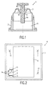
- a liquid-filled damper 1 shows a section of a liquid-filled damper 1, which has a cylindrical base part 2, an elastic cover part 3 that closes off the cylindrical base part 2, and a fastening pin 4 as a fastening element.
- the base part 2 and the cover part 3 enclose a cavity 5 which is filled with oil.
- the fastening pin 4 is arranged centrally within the lid part 3 and extends with an inner part 4a into the cavity 5 and with an outer part 4b outside the cavity 5 and the lid part 3.
- the fastening pin 4 is in an axial central region 4c with the elastic Cover part 3 connected.
- the elastic cover part 3 surrounds the cylindrical fastening pin 4 in an annular manner in the axial central region 4c.
- the base part 2 and the fastening pin 4 preferably consist of a rigid, inelastic plastic.
- the elastic cover part 3 preferably consists of an elastic plastic.
- the liquid-filled damper 1 is preferably manufactured in a multi-component spraying process. In a first process step, the base part 2 and the cylindrical fastening pin 4 are injection molded from plastic. Then oil is introduced into the base part 2 as a viscous material.
- the base part 2 and the fastening pin 4 are arranged in the desired relationship to one another and by a subsequent injection molding process the cover part 3 is formed on the one hand on the fastening pin 4 and on the other hand on the base part 2, whereby the base part 2 and the integrated fastening pin 4 by means of the cover part 3 are connected and thereby the closed cavity 5 is formed.
- the fastening pin 4 is thus elastically supported in relation to the base part 2.
- the inner part 4a of the fastening pin 4 is moved in the oil located in the cavity 5, as a result of which the movement of the fastening pin 4 is damped.
- the fastening pin 4 is intended to be attached either to a vibration-sensitive structural unit of a vibration-sensitive device or to a housing element of the vibration-sensitive device.
- the base part 2 is attached either to the housing element of the vibration-sensitive device or to the vibration-sensitive structural unit. This is described in more detail in FIG. 2.
- Fig. 2 shows an electronic device 6, which for reading from on an optical disc stored information and / or to write information on an optical disk is provided, in particular a CD / DVD player.
- the electronic device 6 has a housing wall 7. Inside the housing wall 7 an optical playback unit 8 is arranged.
- the optical playback unit 8 is with the housing wall 7 by means of four structurally identical dampers 9, 10, 11 and 12 coupled.
- the liquid-filled dampers 9 to 12 correspond to the liquid-filled ones Damper 1 constructed according to FIG. 1.
- the liquid-filled damper 9 to 12 accordingly each have a base part 2, a cover part 3 and a fastening pin 4 on. There is a cavity within each of the liquid-filled dampers 9 to 12 5, which is filled with oil.
- the optical playback unit 8 points for the four liquid-filled ones Dampers 9 to 12 each have a holding device 13 which is fixed to the optical Play unit 8 is connected.
- the holding devices 13 are shown schematically and can e.g. be designed as plastic injection elements.
- the base parts 2 of the liquid-filled Dampers 9 to 12 are fastened in the holding devices 13.
- the attachment can be done in different ways, for example by a positive engagement or click.
- the mounting pins 4 of the liquid-filled damper 9 to 12 are fastened in fastening holes 14 in the housing wall 7.
- the attachment of the Fastening pins 4 in the cylindrical fastening holes 14 of the housing wall 7 can e.g. by pressing or pressing into the mounting holes 14. Furthermore are Snap or click connections possible.
- the liquid-filled dampers 9 to 12 on the one hand by means of the fastening pins 4 and the fastening holes 14 the housing wall 7 and on the other hand by means of the base parts 2 and the holding devices 13 firmly connected to the optical playback unit 8.
- the electronic device 6 is particular intended for installation in a vehicle. The while driving the vehicle Vibrations occurring are on the housing wall 7 of the electronic Transfer device 6. Since the optical playback unit 8 is very sensitive to vibrations, However, the vibrations of the vehicle must not be applied to the optical playback unit 8 be transmitted. This is ensured by means of the liquid-filled dampers 9 to 12, which the optical playback unit 8 floating inside the electronic device 6 store.
- the fastening pins 4 are formed in one piece with the base part 2 and the cover part 3 are, the liquid-filled damper 9 to 12 can be mounted in a simple manner become. No separate mounting of mounting pins and dampers is required. This is advantageous in terms of production technology.
Landscapes
- Engineering & Computer Science (AREA)
- General Engineering & Computer Science (AREA)
- Mechanical Engineering (AREA)
- Combined Devices Of Dampers And Springs (AREA)
- Fluid-Damping Devices (AREA)
Applications Claiming Priority (2)
| Application Number | Priority Date | Filing Date | Title |
|---|---|---|---|
| DE19838753A DE19838753A1 (de) | 1998-08-26 | 1998-08-26 | Flüssigkeitsgefüllter Dämpfer für ein erschütterungsempfindliches Gerät und Verfahren zu dessen Herstellung |
| DE19838753 | 1998-08-26 |
Publications (1)
| Publication Number | Publication Date |
|---|---|
| EP0982514A1 true EP0982514A1 (fr) | 2000-03-01 |
Family
ID=7878754
Family Applications (1)
| Application Number | Title | Priority Date | Filing Date |
|---|---|---|---|
| EP99202706A Withdrawn EP0982514A1 (fr) | 1998-08-26 | 1999-08-23 | Amortisseur à fluide pour dispositif sensible aux vibrations |
Country Status (5)
| Country | Link |
|---|---|
| US (2) | US6603728B1 (fr) |
| EP (1) | EP0982514A1 (fr) |
| JP (1) | JP2000081070A (fr) |
| KR (1) | KR20000017453A (fr) |
| DE (1) | DE19838753A1 (fr) |
Families Citing this family (6)
| Publication number | Priority date | Publication date | Assignee | Title |
|---|---|---|---|---|
| KR100407528B1 (ko) | 2000-09-18 | 2003-11-28 | 아사히 가세이 가부시키가이샤 | 산화 또는 가암모니아산화용 산화물 촉매의 제조 방법 |
| JP4240923B2 (ja) * | 2001-12-14 | 2009-03-18 | ポリマテック株式会社 | ダンパーおよびメカシャーシの防振構造 |
| CN2694431Y (zh) * | 2004-03-19 | 2005-04-20 | 鸿富锦精密工业(深圳)有限公司 | 光盘驱动器减震装置 |
| KR100582950B1 (ko) | 2004-07-23 | 2006-05-25 | 삼성전자주식회사 | 방진장치 및 이를 구비하는 광 디스크 드라이브 |
| US7497505B2 (en) * | 2005-04-29 | 2009-03-03 | Crown Equipment Corporation | Suspended floorboard |
| KR100669287B1 (ko) * | 2005-07-26 | 2007-01-16 | 주식회사 현대오토넷 | 차량용 하드디스크 드라이브 방진 장치 및 그 조립방법 |
Citations (7)
| Publication number | Priority date | Publication date | Assignee | Title |
|---|---|---|---|---|
| FR2218508A1 (fr) * | 1973-02-19 | 1974-09-13 | Pineau Andre | |
| JPS62124332A (ja) * | 1985-11-20 | 1987-06-05 | Matsushita Electric Ind Co Ltd | ダンパ−装置及びその製造方法 |
| JPS62180128A (ja) * | 1986-01-31 | 1987-08-07 | Nec Home Electronics Ltd | 防振装置 |
| US4985884A (en) * | 1987-11-02 | 1991-01-15 | Mitsubishi Denki Kabushiki Kaisha | Disk shaped recording reproduction device |
| DE4234708A1 (de) * | 1991-10-29 | 1993-05-06 | Mitsubishi Denki K.K., Tokio/Tokyo, Jp | Vibrationsdaempfungsvorrichtung |
| JPH0771507A (ja) | 1993-09-02 | 1995-03-17 | Tokai Rubber Ind Ltd | 防振支持装置およびこれに用いられる液体封入ダンパの製造方法 |
| JPH0925988A (ja) * | 1995-07-11 | 1997-01-28 | Matsushita Electric Ind Co Ltd | 制振装置 |
Family Cites Families (6)
| Publication number | Priority date | Publication date | Assignee | Title |
|---|---|---|---|---|
| US4679759A (en) * | 1984-12-24 | 1987-07-14 | Ford Motor Company | Assembly for mounting a vibrating body |
| NL8700969A (nl) * | 1987-04-24 | 1988-11-16 | Philips Nv | Inrichting voor het steunen van een subgestel van een platenspeler op een gestel, alsmede platenspeler voorzien van een dergelijke inrichting. |
| DE19507519A1 (de) * | 1995-03-03 | 1996-09-26 | Hasse & Wrede Gmbh | Viskositäts-Drehschwingungsdämpfer |
| JP3215844B2 (ja) * | 1995-04-18 | 2001-10-09 | キヤノン株式会社 | 表示装置及び該表示装置の製造方法 |
| JP3621349B2 (ja) * | 1998-09-29 | 2005-02-16 | 三菱電機株式会社 | ディスク装置用シャーシの角部補強装置 |
| US6439551B1 (en) * | 1999-08-10 | 2002-08-27 | Polymatech Co., Ltd. | Variable spring constant type damper filled with viscous fluid |
-
1998
- 1998-08-26 DE DE19838753A patent/DE19838753A1/de not_active Withdrawn
-
1999
- 1999-08-19 US US09/377,360 patent/US6603728B1/en not_active Expired - Fee Related
- 1999-08-23 EP EP99202706A patent/EP0982514A1/fr not_active Withdrawn
- 1999-08-23 KR KR1019990034946A patent/KR20000017453A/ko not_active Withdrawn
- 1999-08-24 JP JP11237323A patent/JP2000081070A/ja active Pending
-
2003
- 2003-06-13 US US10/462,304 patent/US20040216151A1/en not_active Abandoned
Patent Citations (7)
| Publication number | Priority date | Publication date | Assignee | Title |
|---|---|---|---|---|
| FR2218508A1 (fr) * | 1973-02-19 | 1974-09-13 | Pineau Andre | |
| JPS62124332A (ja) * | 1985-11-20 | 1987-06-05 | Matsushita Electric Ind Co Ltd | ダンパ−装置及びその製造方法 |
| JPS62180128A (ja) * | 1986-01-31 | 1987-08-07 | Nec Home Electronics Ltd | 防振装置 |
| US4985884A (en) * | 1987-11-02 | 1991-01-15 | Mitsubishi Denki Kabushiki Kaisha | Disk shaped recording reproduction device |
| DE4234708A1 (de) * | 1991-10-29 | 1993-05-06 | Mitsubishi Denki K.K., Tokio/Tokyo, Jp | Vibrationsdaempfungsvorrichtung |
| JPH0771507A (ja) | 1993-09-02 | 1995-03-17 | Tokai Rubber Ind Ltd | 防振支持装置およびこれに用いられる液体封入ダンパの製造方法 |
| JPH0925988A (ja) * | 1995-07-11 | 1997-01-28 | Matsushita Electric Ind Co Ltd | 制振装置 |
Non-Patent Citations (3)
| Title |
|---|
| PATENT ABSTRACTS OF JAPAN vol. 011, no. 344 (M - 640) 11 November 1987 (1987-11-11) * |
| PATENT ABSTRACTS OF JAPAN vol. 012, no. 021 (M - 661) 22 January 1988 (1988-01-22) * |
| PATENT ABSTRACTS OF JAPAN vol. 1997, no. 05 30 May 1997 (1997-05-30) * |
Also Published As
| Publication number | Publication date |
|---|---|
| US20040216151A1 (en) | 2004-10-28 |
| US6603728B1 (en) | 2003-08-05 |
| KR20000017453A (ko) | 2000-03-25 |
| DE19838753A1 (de) | 2000-03-02 |
| JP2000081070A (ja) | 2000-03-21 |
Similar Documents
| Publication | Publication Date | Title |
|---|---|---|
| DE4242789C2 (de) | Beschleunigungssensor | |
| EP1013496B1 (fr) | Appareil indicateur | |
| DE602004003739T2 (de) | Stossdämpfendes Element, Stossdämpfendes Verfahren für eine elektronische Vorrichtung welches dieses Element benutzt, und für dieses Element und dieses Verfahren angepasste elektronische Vorrichtung | |
| EP0962361B1 (fr) | Appareil électronique comprenant une unité sensible aux vibrations | |
| DE19752672C1 (de) | Gehäuse für einen Stellantrieb | |
| DE4036277C2 (de) | Dämpfer | |
| DE10121776B4 (de) | Sensor | |
| DE19838753A1 (de) | Flüssigkeitsgefüllter Dämpfer für ein erschütterungsempfindliches Gerät und Verfahren zu dessen Herstellung | |
| DE102014100073A1 (de) | Befestigungsvorrichtung | |
| DE69827841T2 (de) | Eckteilverstärkngsvorrichtung für gestell einer plattenvorrichtung | |
| DE60109245T2 (de) | Kugelgelenk und Montageverfahren hierfür | |
| EP0847127B1 (fr) | Entraínement électrique | |
| DE19802442C2 (de) | Kabelkappe für eine Vorrichtung zur Bewegungsübertragung | |
| DE19919526B4 (de) | Stellantrieb für einen Kfz-Rückblickspiegel | |
| EP0675295A1 (fr) | Dispositif de fixation | |
| DE4134937C2 (de) | Abdeckvorrichtung | |
| EP0631057A1 (fr) | Joint d'étanchéité pour piston entrainé pneumatiquement | |
| WO2003097427A1 (fr) | Direction a cremaillere | |
| DE102020102430A1 (de) | Kettenführung | |
| DE69903855T2 (de) | Aufzeichnungs- oder wiedergabegerät mit halte- und entnahmevorrichtung für plattenförmige aufzeichnungsmedia | |
| EP0838682A1 (fr) | Dispositif pour positionner un support de bobine dans un boítier en forme de pot | |
| EP0415492B1 (fr) | Appareil d'enregistement et/ou de reproduction | |
| DE4344898C2 (de) | Dämpfungsanordnung für einen Kassettendeckel | |
| DE102007038737A1 (de) | Bodenplatte für eine Sensorbaugruppe, Trägerkörper zur Befestigung der Sensorbaugruppe, Sensorbaugruppe und Befestigungssystem | |
| EP0813203A1 (fr) | Appareil électronique avec mémoire de masse |
Legal Events
| Date | Code | Title | Description |
|---|---|---|---|
| PUAI | Public reference made under article 153(3) epc to a published international application that has entered the european phase |
Free format text: ORIGINAL CODE: 0009012 |
|
| AK | Designated contracting states |
Kind code of ref document: A1 Designated state(s): DE FR GB |
|
| AX | Request for extension of the european patent |
Free format text: AL;LT;LV;MK;RO;SI |
|
| 17P | Request for examination filed |
Effective date: 20000901 |
|
| AKX | Designation fees paid |
Free format text: DE FR GB |
|
| RAP1 | Party data changed (applicant data changed or rights of an application transferred) |
Owner name: KONINKLIJKE PHILIPS ELECTRONICS N.V. Owner name: PHILIPS CORPORATE INTELLECTUAL PROPERTY GMBH |
|
| 17Q | First examination report despatched |
Effective date: 20021022 |
|
| RAP1 | Party data changed (applicant data changed or rights of an application transferred) |
Owner name: KONINKLIJKE PHILIPS ELECTRONICS N.V. Owner name: PHILIPS INTELLECTUAL PROPERTY & STANDARDS GMBH |
|
| STAA | Information on the status of an ep patent application or granted ep patent |
Free format text: STATUS: THE APPLICATION HAS BEEN WITHDRAWN |
|
| 18W | Application withdrawn |
Effective date: 20030704 |