EP0982593A1 - Dispositif de contrôle des procédés de pipettage - Google Patents
Dispositif de contrôle des procédés de pipettage Download PDFInfo
- Publication number
- EP0982593A1 EP0982593A1 EP98115395A EP98115395A EP0982593A1 EP 0982593 A1 EP0982593 A1 EP 0982593A1 EP 98115395 A EP98115395 A EP 98115395A EP 98115395 A EP98115395 A EP 98115395A EP 0982593 A1 EP0982593 A1 EP 0982593A1
- Authority
- EP
- European Patent Office
- Prior art keywords
- liquid
- tot
- detector
- intensity
- evaluation data
- Prior art date
- Legal status (The legal status is an assumption and is not a legal conclusion. Google has not performed a legal analysis and makes no representation as to the accuracy of the status listed.)
- Granted
Links
Images


Classifications
-
- G—PHYSICS
- G01—MEASURING; TESTING
- G01N—INVESTIGATING OR ANALYSING MATERIALS BY DETERMINING THEIR CHEMICAL OR PHYSICAL PROPERTIES
- G01N35/00—Automatic analysis not limited to methods or materials provided for in any single one of groups G01N1/00 - G01N33/00; Handling materials therefor
- G01N35/10—Devices for transferring samples or any liquids to, in, or from, the analysis apparatus, e.g. suction devices, injection devices
- G01N35/1009—Characterised by arrangements for controlling the aspiration or dispense of liquids
- G01N35/1016—Control of the volume dispensed or introduced
- G01N2035/1018—Detecting inhomogeneities, e.g. foam, bubbles, clots
Definitions
- the present invention relates to a device for Monitoring of pipetting processes according to the Preamble of claim 1.
- Light barriers with light source and receiver for example to detect passing Objects are generally known. It is also known that gas bubbles contained in a liquid jet due to their optical density deviating from the beam are recognizable. Leave gas bubbles in a liquid jet therefore always with the help of a suitable Detect light barrier. A facility for this takes place For example, in WO97 / 33154.
- the invention is therefore based on the object to provide a device of the type mentioned in the introduction, with the sucking in and ejecting the Liquids from the pipetting needles of automatic analyzers monitored as closely as possible to avoid analysis errors can be. In particular, this effect is supposed to be achieved through a non-contact, optical device.
- a pipetting needle 12 As shown in Fig. 1, there is one to be ejected (First) liquid 11 in a pipetting needle 12. This The needle is inserted into a cuvette vessel 13 and dips their tip into another (second) liquid 14, the the liquid 11 to be ejected is to be added. A flexible hose 15 is attached to the pipetting needle 12 connected via which the suction or ejection of the Liquid 11 is controlled by pressure change. From the Pipetting needle 12 becomes a minimum of 1 microliter Sample liquid 11 ejected.
- first liquid well defined in volume 11 is to distinguish it from a (third), in Hose 15 and the upper area of the pipetting needle 12 remaining hydraulic purposes Working fluid 16 a separation bubble 17.
- a protective bladder 27 In the top of the Needle 12 to the first liquid 11 is located a protective bladder 27 that the pipetting needle 12 to the outside almost closed and, above all, unwanted leakage prevented from parts of the first liquid 11.
- the device shown in FIG. 1 comprises one Light source 18, for example an LED (light emitting diode) for emitting a light beam 19 in the near infrared (e.g. at approx. 900 nm), and an assigned light detector 20.
- detector electronics 22 This is followed by detector electronics 22.
- the light beam 19 passes through the cuvette vessel 13 and the liquid 14 contained therein is relatively wide and oblique, resulting in the appearance of bubbles due to total reflections the bubble walls in the detector 20 major changes in the received light intensity occur.
- the detector 20 is for Elimination of disturbing background radiation by a Aperture 21 shielded from the outside. It can be based on this Evidence of even the smallest bubbles that result from the Needle 11 are expelled into the second liquid 14 and slowly rise in it.
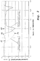
- Figure 2 shows the typical course of the output signal U of the light detector 20 depending on the time t for two different cases.
- the required amount (first) of liquid 11 is bubble-free in the pipetting needle 12.
- it shows up a first minimum 31 at the beginning of the ejection process shallow depth, which is caused by the ejected protective bubble 27 is effected.
- the following relative maximum 32 goes to the ejected first liquid 11.
- part of the separating bubble 17 follows a second, lower minimum 33 causes.
- FIG. 3 shows the block diagram of the detector electronics 22.
- This unit 22 comprises a first 22.1 and a second memory 22.2 and two logic circuits 22.3, 22.4. It emits a control signal to the outside via the connection 27 and receives its measurement signals U n from the light detector 20.
- Comparison values are stored in the memory 22.1 Typical intensity / time profiles shown in FIG correspond. These comparison values preferably serve as Thresholds S.
- the intensity values determined during the ejection of the liquid 11 from the pipetting needle 12 or the measurement signals U n are continuously stored, so that a sequence of measurement values is available for processing.
- These measured values U n can be filtered to avoid statistical fluctuations, for example by averaging from z. B. five adjacent individual values.
- the quotient of these difference values and the time, ie dU n / dt, corresponds to the respective slopes of the curves in FIG. 2.
- Important conclusions can already be drawn from these slopes, in particular from their mean values and the points in time.
- the minima and / or maxima of the respective intensity / time curve can also be determined from the sequence of the difference values dU n , and from the intensity values themselves the assigned intensities at the extreme points.
- the slopes and the values at the extreme points form first evaluation data B m (m: 1, 2, 3,
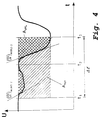
- Integrals A are used to obtain further evaluation data, ie areas are determined which are essentially limited by the intensity / time profiles according to FIG. 4 shows a diagram corresponding to FIG. 2.
- the integral A m corresponds to the area above the respective diagram curve, starting at the starting point t 1 and ending at a predetermined time ⁇ t later at the ending point t 3 .
- the integral A tot corresponds to the assigned rectangular area spanned by the point t 1 and the time ⁇ t.
- the ratio A m / A tot of these respective integrals forms a further evaluation date.
- the evaluation data are in the second logic circuit 22.4 each with those from the first memory 22.1 set threshold value compared. As soon as descriptive criteria are met, the logic circuit gives 22.4 over the connection 27 either an end signal E or an error signal F from.
- the detector electronics 22 can be made in a conventional manner Circuits, e.g. B. using Operational amplifiers. In a preferred manner however, it is a program-controlled Processor and allocated memory, in which the Logic circuits 22.3, 22.4 through special program parts that run in series, are realized.
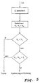
- FIG. 5 shows a very simple flow chart, which shows the overall function of the detector electronics 22.
- the intensity values U n output by the detector 20 are stored as raw data in the memory 22.2. They are used in the first processing steps to calculate the above-mentioned evaluation data B m , A m / A tot .
- This is essentially followed by two decision steps in which it is checked whether or not the first evaluation data B m correspond to the conditions given by the stored threshold values S and whether the ratio of the integrals A n / A tot does not exceed a further threshold value S i . If the decision responses correspond to the conditions when the pipetting is carried out correctly, then there is a positive end signal. Otherwise there may be an error. This result is either reacted with a hard stop signal or the repetition of the pipetting process is initiated.
- the threshold values S can be correctly determined with comparable samples.
- a zero adjustment is also necessary, at least after each Initialization process. This can cause disruptive factors like different volume of the second liquid 14, different transparency, refractive index and / or Viscosity of liquids 11 and / or 14 and Eliminate or at least minimize cell vessel 13.
- the favorable properties of the device according to the invention are based primarily on its essentially dynamic principle, which consists in the skillful evaluation of an extensive sequence of measured values. It is also important that two different types of values are used, firstly the slopes dU n / dt and secondly integrals A. This significantly increases the ability to make decisions when detecting possible errors.
- a device for monitoring pipetting processes and in particular the escape of a first liquid 11 from a pipetting needle 12, the tip of which is immersed in a second liquid 14, has been described above.
- This device contains a source 18 for a light beam 19, which runs transverse to the path of the first liquid 11, and a light detector 20 at the end of the light beam 19 for emitting an output signal corresponding to the respective received light intensity.
- the detector 20 is designed to continuously output intensity signals or measurement signals U n .
- the device also contains a first memory 22.1 for pre-determined threshold values S, a second memory 22.2 for the current intensity signals or measurement signals U n and for evaluation data B m , A m / A tot derived therefrom, and at least one logic circuit 22.3, 22.4 for comparison the evaluation data B m , A m / A tot with the threshold values S and for outputting a result signal E, F.
Landscapes
- Immunology (AREA)
- Pathology (AREA)
- Life Sciences & Earth Sciences (AREA)
- Chemical & Material Sciences (AREA)
- Analytical Chemistry (AREA)
- Biochemistry (AREA)
- General Health & Medical Sciences (AREA)
- General Physics & Mathematics (AREA)
- Health & Medical Sciences (AREA)
- Physics & Mathematics (AREA)
- Investigating Or Analysing Materials By Optical Means (AREA)
- Automatic Analysis And Handling Materials Therefor (AREA)
- Sampling And Sample Adjustment (AREA)
- Pipeline Systems (AREA)
- Investigating Or Analyzing Materials By The Use Of Ultrasonic Waves (AREA)
- Measurement Of Levels Of Liquids Or Fluent Solid Materials (AREA)
- Length Measuring Devices By Optical Means (AREA)
Priority Applications (6)
| Application Number | Priority Date | Filing Date | Title |
|---|---|---|---|
| DE59813265T DE59813265D1 (de) | 1998-08-17 | 1998-08-17 | Verfahren zur Ueberwachung von Pipettiervorgängen |
| ES98115395T ES2253797T3 (es) | 1998-08-17 | 1998-08-17 | Dispositivo para el control de los procesos de pipeteado. |
| EP98115395A EP0982593B1 (fr) | 1998-08-17 | 1998-08-17 | Méthode de contrôle des procédés de pipettage |
| AT98115395T ATE312355T1 (de) | 1998-08-17 | 1998-08-17 | Verfahren zur ueberwachung von pipettiervorgängen |
| US09/371,979 US6281517B1 (en) | 1998-08-17 | 1999-08-11 | Apparatus for monitoring pipetting operations |
| JP23002699A JP4355059B2 (ja) | 1998-08-17 | 1999-08-16 | 分注動作の監視装置 |
Applications Claiming Priority (1)
| Application Number | Priority Date | Filing Date | Title |
|---|---|---|---|
| EP98115395A EP0982593B1 (fr) | 1998-08-17 | 1998-08-17 | Méthode de contrôle des procédés de pipettage |
Publications (2)
| Publication Number | Publication Date |
|---|---|
| EP0982593A1 true EP0982593A1 (fr) | 2000-03-01 |
| EP0982593B1 EP0982593B1 (fr) | 2005-12-07 |
Family
ID=8232464
Family Applications (1)
| Application Number | Title | Priority Date | Filing Date |
|---|---|---|---|
| EP98115395A Expired - Lifetime EP0982593B1 (fr) | 1998-08-17 | 1998-08-17 | Méthode de contrôle des procédés de pipettage |
Country Status (6)
| Country | Link |
|---|---|
| US (1) | US6281517B1 (fr) |
| EP (1) | EP0982593B1 (fr) |
| JP (1) | JP4355059B2 (fr) |
| AT (1) | ATE312355T1 (fr) |
| DE (1) | DE59813265D1 (fr) |
| ES (1) | ES2253797T3 (fr) |
Cited By (3)
| Publication number | Priority date | Publication date | Assignee | Title |
|---|---|---|---|---|
| WO2002073215A3 (fr) * | 2001-03-09 | 2004-02-26 | Hamilton Bonaduz Ag | Procede et dispositif d'evaluation d'un processus de dosage de liquide |
| EP1760472A1 (fr) * | 2005-08-29 | 2007-03-07 | Sysmex Corporation | Procédé et dispositif pour la surveillance de l'aspiration d'un liquide |
| EP2031403A1 (fr) | 2007-08-27 | 2009-03-04 | Roche Diagnostics GmbH | Procédé de surveillance d'un procédé de transfert de fluides |
Families Citing this family (7)
| Publication number | Priority date | Publication date | Assignee | Title |
|---|---|---|---|---|
| AU2004201406B2 (en) * | 1996-08-16 | 2007-05-17 | Ge Healthcare Niagara Inc. | A digital imaging system for assays in well plates, gels and blots |
| US20070031818A1 (en) * | 2004-07-15 | 2007-02-08 | Cytokinetics, Inc., A Delaware Corporation | Assay for distinguishing live and dead cells |
| US8165919B2 (en) | 2006-03-31 | 2012-04-24 | Digital River, Inc. | Web based product ordering method with shopping carts actions queued |
| EP2112514A1 (fr) * | 2008-04-24 | 2009-10-28 | bioMérieux BV | Procédé et appareil de vérification du fluide dans l'extrémité d'une pipette |
| DE102017212196A1 (de) * | 2017-07-17 | 2019-01-17 | Robert Bosch Gmbh | Verfahren und Steuergerät zum Detektieren von Blasen in einer Fluidkammer eines fluidischen Systems und fluidisches System |
| CN110941855B (zh) * | 2019-11-26 | 2022-02-15 | 电子科技大学 | 一种AIoT场景下的神经网络模型窃取防御方法 |
| CN115141740B (zh) * | 2022-05-24 | 2026-03-10 | 广州万孚生物技术股份有限公司 | 液体注入的监控方法、系统、装置、设备和介质 |
Citations (4)
| Publication number | Priority date | Publication date | Assignee | Title |
|---|---|---|---|---|
| DE4211003A1 (de) * | 1991-04-04 | 1992-10-08 | Olympus Optical Co | Vorrichtung und verfahren zum detektieren des volumens einer ausgetragenen fluessigkeit |
| US5559339A (en) * | 1994-10-31 | 1996-09-24 | Abbott Laboratories | Method and apparatus for verifying dispense of a fluid from a dispense nozzle |
| WO1997033154A1 (fr) * | 1996-03-07 | 1997-09-12 | Octagon Ab | Detecteur de bulles |
| DE19630160A1 (de) * | 1996-07-26 | 1998-01-29 | Boehringer Mannheim Gmbh | Analysesystem mit Mitteln zur Erkennung von Unterdosierungen |
Family Cites Families (6)
| Publication number | Priority date | Publication date | Assignee | Title |
|---|---|---|---|---|
| CH587486A5 (fr) * | 1974-11-29 | 1977-05-13 | Hoffmann La Roche | |
| ATE3371T1 (de) * | 1980-04-23 | 1983-06-15 | Contraves Ag | Sensorkanuele. |
| US5125748A (en) * | 1986-03-26 | 1992-06-30 | Beckman Instruments, Inc. | Optical detection module for use in an automated laboratory work station |
| US4979821A (en) * | 1988-01-27 | 1990-12-25 | Ortho Diagnostic Systems Inc. | Cuvette for receiving liquid sample |
| JPH0781996B2 (ja) * | 1988-08-27 | 1995-09-06 | 株式会社日立製作所 | オートサンプラ |
| JPH08338849A (ja) * | 1995-04-11 | 1996-12-24 | Precision Syst Sci Kk | 液体の吸引判別方法およびこの方法により駆動制御される分注装置 |
-
1998
- 1998-08-17 EP EP98115395A patent/EP0982593B1/fr not_active Expired - Lifetime
- 1998-08-17 AT AT98115395T patent/ATE312355T1/de not_active IP Right Cessation
- 1998-08-17 DE DE59813265T patent/DE59813265D1/de not_active Expired - Lifetime
- 1998-08-17 ES ES98115395T patent/ES2253797T3/es not_active Expired - Lifetime
-
1999
- 1999-08-11 US US09/371,979 patent/US6281517B1/en not_active Expired - Fee Related
- 1999-08-16 JP JP23002699A patent/JP4355059B2/ja not_active Expired - Fee Related
Patent Citations (4)
| Publication number | Priority date | Publication date | Assignee | Title |
|---|---|---|---|---|
| DE4211003A1 (de) * | 1991-04-04 | 1992-10-08 | Olympus Optical Co | Vorrichtung und verfahren zum detektieren des volumens einer ausgetragenen fluessigkeit |
| US5559339A (en) * | 1994-10-31 | 1996-09-24 | Abbott Laboratories | Method and apparatus for verifying dispense of a fluid from a dispense nozzle |
| WO1997033154A1 (fr) * | 1996-03-07 | 1997-09-12 | Octagon Ab | Detecteur de bulles |
| DE19630160A1 (de) * | 1996-07-26 | 1998-01-29 | Boehringer Mannheim Gmbh | Analysesystem mit Mitteln zur Erkennung von Unterdosierungen |
Cited By (6)
| Publication number | Priority date | Publication date | Assignee | Title |
|---|---|---|---|---|
| WO2002073215A3 (fr) * | 2001-03-09 | 2004-02-26 | Hamilton Bonaduz Ag | Procede et dispositif d'evaluation d'un processus de dosage de liquide |
| US6938504B2 (en) | 2001-03-09 | 2005-09-06 | Hamilton Bonaduz Ag | Method and device for evaluating a liquid dosing process |
| EP1760472A1 (fr) * | 2005-08-29 | 2007-03-07 | Sysmex Corporation | Procédé et dispositif pour la surveillance de l'aspiration d'un liquide |
| US8252235B2 (en) | 2005-08-29 | 2012-08-28 | Sysmex Corporation | Monitoring method, monitoring apparatus, and liquid sample analyzer |
| US8821791B2 (en) | 2005-08-29 | 2014-09-02 | Sysmex Corporation | Monitoring method, monitoring apparatus and liquid sample analyzer |
| EP2031403A1 (fr) | 2007-08-27 | 2009-03-04 | Roche Diagnostics GmbH | Procédé de surveillance d'un procédé de transfert de fluides |
Also Published As
| Publication number | Publication date |
|---|---|
| ES2253797T3 (es) | 2006-06-01 |
| ATE312355T1 (de) | 2005-12-15 |
| JP4355059B2 (ja) | 2009-10-28 |
| EP0982593B1 (fr) | 2005-12-07 |
| US6281517B1 (en) | 2001-08-28 |
| DE59813265D1 (de) | 2006-01-12 |
| JP2000088865A (ja) | 2000-03-31 |
Similar Documents
| Publication | Publication Date | Title |
|---|---|---|
| DE69913424T2 (de) | Inkrementaler Absorptionsabtastung von Flüssigkeit in einer Abgabespitze | |
| DE3438798C2 (de) | Verfahren und Vorrichtung zum Messen der Feststoffkonzentration und der Korngrößenverteilung in einer Suspension mittels Ultraschall | |
| EP3052934B1 (fr) | Procédé de reconnaissance d'un état d'un échantillon, dispositif d'analyse des échantillons et système de laboratoire automatique | |
| DE3009835A1 (de) | Verfahren und vorrichtung zur bestimmung der eigenschaften eines segmentierten fluids, ohne in das fluid einzudringen | |
| DE2459111C3 (de) | Verfahren und Vorrichtung zur photometrischen Analyse flüssiger Proben | |
| WO2008000433A1 (fr) | Détecteur spectroscopique et procédé pour déterminer la présence de sang et de marqueurs biologiques dans des liquides | |
| DE2436110B2 (de) | Vorrichtung zur Feststellung von Herstellungsfehlern in einer bewegten Materialbahn | |
| DE2656654B2 (de) | Vorrichtung zur Messung des Volumens und bestimmter optischer Eigenschaften von Partikeln | |
| DE2349271A1 (de) | Vorrichtung zum ermitteln von parametern von blutzellen | |
| EP0982593B1 (fr) | Méthode de contrôle des procédés de pipettage | |
| DE69525570T2 (de) | Probensammler für flüssige Proben | |
| DE69322122T2 (de) | Verfahren und Vorrichtung zur Überwachung der Abgabe einer Flüssigkeit | |
| DE3113248C2 (de) | Vorrichtung zur Entnahme von Flüssigkeiten aus Behältern im Analysenmaßstab | |
| DE3418283A1 (de) | Verfahren zum nachweis von fehlstellen in transparenten materialien | |
| DE3307789A1 (de) | Verfahren und vorrichtung zur anzeige einer aenderung des zerfallpunktes in einem tropfenerzeugungssystem | |
| EP0990908A1 (fr) | Analyseur automatisé avec moyens de controle des procédures de pipettage | |
| DE2050672C3 (de) | Durchflußküvette zur mikroskopfotometrischen Messung von in einer Flüssigkeit suspendierten Teilchen | |
| DE2419362A1 (de) | Verfahren und vorrichtung zum ermitteln der form von zellkernen | |
| DE3779744T2 (de) | Verfahren und vorrichtung zum nachweis von fremdkoerpern, wie luftblaeschen in einer fluessigkeit. | |
| DE2245734A1 (de) | Vorrichtung zum feststellen von oberflaechenfehlern | |
| DE3706458C2 (fr) | ||
| DE1673136A1 (de) | Verfahren und Vorrichtung zur Analyse von stroemenden Fluessigkeitsproben | |
| EP3136083B1 (fr) | Procede et dispositif de determination d'une matiere ou d'une concentration de matiere dans un milieu liquide | |
| DE2134937C2 (de) | Verfahren und Vorrichtung zum Erfassen von in einer Flüssigkeit suspendierten Teilchen | |
| DE60001733T2 (de) | Verfahren und vorrichtung zur bestimmung der qualität von trauben |
Legal Events
| Date | Code | Title | Description |
|---|---|---|---|
| PUAI | Public reference made under article 153(3) epc to a published international application that has entered the european phase |
Free format text: ORIGINAL CODE: 0009012 |
|
| AK | Designated contracting states |
Kind code of ref document: A1 Designated state(s): AT CH DE ES FR GB IT LI NL |
|
| AX | Request for extension of the european patent |
Free format text: AL;LT;LV;MK;RO;SI |
|
| 17P | Request for examination filed |
Effective date: 20000624 |
|
| AKX | Designation fees paid |
Free format text: AT CH DE ES FR GB IT LI NL |
|
| 17Q | First examination report despatched |
Effective date: 20040716 |
|
| GRAP | Despatch of communication of intention to grant a patent |
Free format text: ORIGINAL CODE: EPIDOSNIGR1 |
|
| RTI1 | Title (correction) |
Free format text: METHOD FOR MONITORING PIPETTING OPERATIONS |
|
| GRAS | Grant fee paid |
Free format text: ORIGINAL CODE: EPIDOSNIGR3 |
|
| GRAA | (expected) grant |
Free format text: ORIGINAL CODE: 0009210 |
|
| AK | Designated contracting states |
Kind code of ref document: B1 Designated state(s): AT CH DE ES FR GB IT LI NL |
|
| REG | Reference to a national code |
Ref country code: GB Ref legal event code: FG4D Free format text: NOT ENGLISH |
|
| REG | Reference to a national code |
Ref country code: CH Ref legal event code: NV Representative=s name: VENTOCILLA PATENT AG Ref country code: CH Ref legal event code: EP |
|
| REF | Corresponds to: |
Ref document number: 59813265 Country of ref document: DE Date of ref document: 20060112 Kind code of ref document: P |
|
| GBT | Gb: translation of ep patent filed (gb section 77(6)(a)/1977) |
Effective date: 20060315 |
|
| REG | Reference to a national code |
Ref country code: ES Ref legal event code: FG2A Ref document number: 2253797 Country of ref document: ES Kind code of ref document: T3 |
|
| ET | Fr: translation filed | ||
| PLBE | No opposition filed within time limit |
Free format text: ORIGINAL CODE: 0009261 |
|
| STAA | Information on the status of an ep patent application or granted ep patent |
Free format text: STATUS: NO OPPOSITION FILED WITHIN TIME LIMIT |
|
| 26N | No opposition filed |
Effective date: 20060908 |
|
| PGFP | Annual fee paid to national office [announced via postgrant information from national office to epo] |
Ref country code: NL Payment date: 20080715 Year of fee payment: 11 Ref country code: CH Payment date: 20080708 Year of fee payment: 11 |
|
| PGFP | Annual fee paid to national office [announced via postgrant information from national office to epo] |
Ref country code: AT Payment date: 20080708 Year of fee payment: 11 |
|
| REG | Reference to a national code |
Ref country code: NL Ref legal event code: V1 Effective date: 20100301 Ref country code: CH Ref legal event code: PL |
|
| PG25 | Lapsed in a contracting state [announced via postgrant information from national office to epo] |
Ref country code: LI Free format text: LAPSE BECAUSE OF NON-PAYMENT OF DUE FEES Effective date: 20090831 Ref country code: CH Free format text: LAPSE BECAUSE OF NON-PAYMENT OF DUE FEES Effective date: 20090831 |
|
| PG25 | Lapsed in a contracting state [announced via postgrant information from national office to epo] |
Ref country code: AT Free format text: LAPSE BECAUSE OF NON-PAYMENT OF DUE FEES Effective date: 20090817 |
|
| PG25 | Lapsed in a contracting state [announced via postgrant information from national office to epo] |
Ref country code: NL Free format text: LAPSE BECAUSE OF NON-PAYMENT OF DUE FEES Effective date: 20100301 |
|
| PGFP | Annual fee paid to national office [announced via postgrant information from national office to epo] |
Ref country code: GB Payment date: 20120726 Year of fee payment: 15 |
|
| PGFP | Annual fee paid to national office [announced via postgrant information from national office to epo] |
Ref country code: ES Payment date: 20120809 Year of fee payment: 15 Ref country code: DE Payment date: 20120831 Year of fee payment: 15 Ref country code: IT Payment date: 20120820 Year of fee payment: 15 Ref country code: FR Payment date: 20120809 Year of fee payment: 15 |
|
| GBPC | Gb: european patent ceased through non-payment of renewal fee |
Effective date: 20130817 |
|
| PG25 | Lapsed in a contracting state [announced via postgrant information from national office to epo] |
Ref country code: DE Free format text: LAPSE BECAUSE OF NON-PAYMENT OF DUE FEES Effective date: 20140301 |
|
| REG | Reference to a national code |
Ref country code: FR Ref legal event code: ST Effective date: 20140430 |
|
| PG25 | Lapsed in a contracting state [announced via postgrant information from national office to epo] |
Ref country code: IT Free format text: LAPSE BECAUSE OF NON-PAYMENT OF DUE FEES Effective date: 20130817 |
|
| REG | Reference to a national code |
Ref country code: DE Ref legal event code: R119 Ref document number: 59813265 Country of ref document: DE Effective date: 20140301 |
|
| PG25 | Lapsed in a contracting state [announced via postgrant information from national office to epo] |
Ref country code: GB Free format text: LAPSE BECAUSE OF NON-PAYMENT OF DUE FEES Effective date: 20130817 |
|
| PG25 | Lapsed in a contracting state [announced via postgrant information from national office to epo] |
Ref country code: FR Free format text: LAPSE BECAUSE OF NON-PAYMENT OF DUE FEES Effective date: 20130902 |
|
| PG25 | Lapsed in a contracting state [announced via postgrant information from national office to epo] |
Ref country code: ES Free format text: LAPSE BECAUSE OF NON-PAYMENT OF DUE FEES Effective date: 20130818 |