EP0982883A2 - Emetteur optique et système de transmission optique - Google Patents
Emetteur optique et système de transmission optique Download PDFInfo
- Publication number
- EP0982883A2 EP0982883A2 EP19990306521 EP99306521A EP0982883A2 EP 0982883 A2 EP0982883 A2 EP 0982883A2 EP 19990306521 EP19990306521 EP 19990306521 EP 99306521 A EP99306521 A EP 99306521A EP 0982883 A2 EP0982883 A2 EP 0982883A2
- Authority
- EP
- European Patent Office
- Prior art keywords
- polarization
- optical
- modulator
- optical transmitter
- optical signal
- Prior art date
- Legal status (The legal status is an assumption and is not a legal conclusion. Google has not performed a legal analysis and makes no representation as to the accuracy of the status listed.)
- Withdrawn
Links
- 230000005540 biological transmission Effects 0.000 title claims abstract description 59
- 230000003287 optical effect Effects 0.000 title claims description 129
- 230000010287 polarization Effects 0.000 claims abstract description 182
- 229940125730 polarisation modulator Drugs 0.000 claims abstract description 52
- 239000006185 dispersion Substances 0.000 claims description 63
- GQYHUHYESMUTHG-UHFFFAOYSA-N lithium niobate Chemical compound [Li+].[O-][Nb](=O)=O GQYHUHYESMUTHG-UHFFFAOYSA-N 0.000 claims description 29
- 239000013307 optical fiber Substances 0.000 claims description 23
- 239000000463 material Substances 0.000 claims 2
- 230000000694 effects Effects 0.000 description 17
- 230000015556 catabolic process Effects 0.000 description 9
- 238000010276 construction Methods 0.000 description 9
- 238000006731 degradation reaction Methods 0.000 description 9
- 239000000470 constituent Substances 0.000 description 3
- 238000010586 diagram Methods 0.000 description 3
- 238000005516 engineering process Methods 0.000 description 3
- 230000003993 interaction Effects 0.000 description 3
- 238000009825 accumulation Methods 0.000 description 2
- 238000000034 method Methods 0.000 description 2
- 230000002238 attenuated effect Effects 0.000 description 1
- 238000005388 cross polarization Methods 0.000 description 1
- 230000000593 degrading effect Effects 0.000 description 1
- 239000000835 fiber Substances 0.000 description 1
- 230000004048 modification Effects 0.000 description 1
- 238000012986 modification Methods 0.000 description 1
Images


Classifications
-
- H—ELECTRICITY
- H04—ELECTRIC COMMUNICATION TECHNIQUE
- H04B—TRANSMISSION
- H04B10/00—Transmission systems employing electromagnetic waves other than radio-waves, e.g. infrared, visible or ultraviolet light, or employing corpuscular radiation, e.g. quantum communication
- H04B10/50—Transmitters
- H04B10/516—Details of coding or modulation
- H04B10/532—Polarisation modulation
Definitions
- the present invention relates in general to an optical transmitter and an optical transmission system each of which subjects an optical signal to either polarization modulation or polarization scrambling, and more particularly to an optical transmitter and an optical transmission system each of which is capable of suppressing the polarization dispersion of the polarization modulator.
- optical fiber amplifiers has enabled, even in transmission distances over several thousands of kilometers, signals to be transmitted without carrying out electrical reproduction and repetition in repeaters.
- the polarization dependency effect is meant that the influence which is exerted on the optical signal, when the optical signal is passing through the transmission system differs, depending on the polarization state of the optical signal.
- the polarization dependency effect contains therein the polarization dispersion, the polarization dependency loss, the polarization hole burning in the repeating amplifier, and the like.
- a polarization modulator has a birefringence
- a lithium niobate (LN) waveguide has a relatively large birefringence.
- birefringence is meant the property in which the propagation speed of light differs between two polarization axes.
- the polarization dispersion is the delay difference which occurs between the light beams passing through the two polarization axes, respectively, due to the presence of the birefringence.
- the polarization dependency loss is the transmission loss which the optical signal suffers, and differs depending on the polarization state of the optical signal.
- Each of the optical fiber and the repeating amplifier which are employed in the transmission path is designed normally in such a way that the polarization dependency loss is reduced as much as possible.
- the polarization dependency loss is, while a very small amount, contained in particular in the devices which are employed in the repeating amplifier.
- the optical signal is in the polarization state in which the polarization of the optical signal coincides with the polarization axis having the larger loss, then the optical signal component is excessively attenuated so that noise light having the opposite polarization state is increased in level. As a result, the signal-to-noise ratio is, while a very small amount, degraded.
- the conventional polarization modulator has the polarization dependency effect, and has the birefringence characteristic as one of them therein.
- the LN waveguide has a relatively large birefringence, the propagation speed of light differs between the two polarization axes. For this reason, a delay difference occurs between the light beams passing through the two polarization axes, respectively, and it results in the polarization dispersion.
- the optical signal passing through the polarization modulator is produced by superposing the two optical signals which are shifted on the time base by the delay difference, which degrades the transmission characteristics.
- an optical transmitter for modulating the polarization of an optical signal supplied through an input terminal, the optical transmitter including: a polarization modulator; and at least one birefringence device which is connected to at least one of the preceding stage or the following stage of the polarization modulator in such a way that the fast axis and slow axis thereof are aligned with the slow axis and the fast axis of the polarization modulator, and in which the total amount of polarization dispersion is substantially equal to or compensates at least in part for the amount of polarization dispersion of the polarization modulator.
- an optical transmission system for transmitting an optical signal, the system including: the above-mentioned optical transmitter according to the above aspect; an optical transmission path to which an optical signal which has been outputted from the optical transmitter is inputted; and an optical receiver for receiving the optical signal outputted through the optical transmission path.
- the birefringence device which has the polarization dispersion amount corresponding to the polarization dispersion amount of the polarization modulator is connected to the polarization modulator, whereby it is possible to cancel out the polarization dispersion amount which is applied by the polarization modulation.
- the polarization dispersion of the polarization modulator which occupies the large ratio in the total polarization dispersion in the transmission system is removed, whereby the better transmission characteristics can be expected.
- the polarization modulator which is used in the optical transmitter has the birefringence.
- the lithium niobate (LN) waveguide has the relatively large birefringence. The delay difference occurs between the light beams which pass through the two polarization axes perpendicularly intersecting each other, respectively, due to the presence of the birefringence, and it becomes the polarization dispersion.
- Figs. 1 and 2 are respectively schematic views each useful in explaining the influence which is exerted on an optical signal by the polarization dispersion when the optical signal is passing through a device having the birefringence.
- Fig. 1 after an optical signal in the polarization state having a predetermined angle has passed the above-mentioned device 10, specific cross polarization components 14a and 14b of the device become outputs 15a and 15b, respectively, which have a delay difference 16 on the time axis.
- Fig. 2 is a schematic view showing an example of commercially available LN polarization modulator and which has signal supply lines 3 for the polarization modulation.
- the LN polarization modulator has the polarization dispersion of about 15 ps or so between two polarization axes 21 and 22.
- the output optical signal is produced by superposing the two optical signals which are shifted on the time base by about 15 ps.
- the transmission rate is 10 Gb/s
- the time width which is occupied by one signal bit is only at most 100 ps, the polarization dispersion of about 15 ps results in the degradation of the transmission characteristics.
- each of the optical fiber and the repeating amplifier which are employed in the transmission path is designed in such a way that the polarization dependency loss therein is reduced as much as possible.
- the polarization dependency loss is, while a very small amount, contained in each of the devices which are employed in the repeating amplifier.
- the wavelength-division multiplexed transmission system wherein the polarization scrambling technology is utilized in the channels and then the interaction between the channels is reduced is disclosed in Japanese Patent Application Laid-open No. Hei 8-237225.
- Fig. 3 is a block diagram showing a configuration of the wavelength-division multiplexed transmission system disclosed in Japanese Patent Application Laid-open No. Hei 8-237225.
- Optical signals emitted from a plurality of light sources 30-1 to 30-N and which have the different wavelengths are wavelength-multiplexed by respective polarization controllers and an N x 1 multiplexer 31.
- the optical signal which has been obtained through the wavelength multiplexing is subjected to the polarization modulation by a polarization modulator 32.
- the output optical signal from the polarization modulator 32 is set by a high birefringence fiber 33 in such a way that the polarization states of the wavelengths of the adjacent channels perpendicularly intersect each other.
- the polarization dispersion is intentionally added to the wavelength-multiplexed signal.
- the polarization states between the adjacent channels are made perpendicularly intersect each other. For example, when the channel interval is made 100 GHz, this state can be realized by adding the polarization dispersion of about 5 ps to the wavelength-multiplexed signal.
- the birefringence device is inserted into the position after the polarization modulator 32.
- the conventional polarization modulator has the polarization dependency effect, and has the birefringence characteristic as one of them therein.
- the LN waveguide since the LN waveguide has the relatively large birefringence, the propagation speed of light differs between the two polarization axes. For this reason, the delay difference occurs between the light beams passing through the two polarization axes, respectively, and it becomes the polarization dispersion.
- the optical signal passing through the polarization modulator is produced by superposing the two optical signals which are shifted on the time base by the delay difference, which degrades the transmission characteristics.
- the polarization dispersion amount resulting therefrom is different from the polarization dispersion amount which is suitable for suppressing the degradation, of the transmission characteristics, which is caused by the polarization dispersion.
- the excessive addition of the polarization dispersion to the optical signal results in the degradation of the transmission quality, and in particular, this effect is increased as the bit rate is further increased. Therefore, in improving the bit rate, it is required to take the measures of reducing any of the influences which are exerted on the optical signal of the polarization dispersion contained in the polarization modulator.
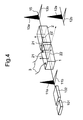
- Fig. 4 is a schematic view showing a construction of the optical transmitter according to the present embodiment.
- the optical transmitter of the present embodiment includes: a light source 101; an intensity modulator 102 for subjecting an optical signal which has been emitted from the light source 101 on the basis of the transmission data to the intensity modulation; and a polarization modulator 22 for polarization-modulating the optical signal outputted from the intensity modulator.
- the polarization modulator 22 includes a waveguide 1 for the polarization modulation and a birefringence device 2 for compensating for the polarization dispersion which device is provided on the output side of the waveguide 1 for the polarization modulation.
- the optical signal (the input optical signal) which has been outputted from the intensity modulator 102 has both of a component (a fast axis component) 11a of a polarization axis 21 having the relatively large propagation speed in the waveguide 1 for the polarization modulation and a component (a slow axis component) 11b of a polarization axis 22 having the relatively small propagation speed therein.
- the input optical signal is inputted to the waveguide 1 for the polarization modulation so as to fulfill the above-mentioned relationship between the polarization axes.
- the optical signal which has been outputted from the waveguide 1 for the polarization modulation is then inputted to the birefringence device for compensating for the polarization dispersion.
- Both of the fast axis component lla of the waveguide for the polarization modulation in the input optical signal and the slow axis component 11b of the waveguide for the polarization modulation in the input optical signal suffer the polarization dispersion in the waveguide 1 for the polarization modulation to become a fast axis component 12a of the waveguide for the polarization modulation in the output optical signal from the waveguide for the polarization modulation and a slow axis component 12b of the waveguide for the polarization modulation in the output optical signal from the waveguide for the polarization modulation, respectively.
- This optical signal suffers the polarization dispersion in the opposite direction in the birefringence device 2 for compensating for the polarization dispersion.
- the output optical signal from the birefringence device 2 for compensating for the polarization dispersion has a fast axis component 13a of the waveguide for the polarization modulation in the output optical signal and a slow axis component 13b of the waveguide for the polarization modulation in the output optical signal, so that it is possible to substantially exclude the degradation of the transmission characteristics due to the influences of the polarization dispersion.
- the LN waveguide having the polarization dispersion is employed as the waveguide 1 for the polarization modulation, and also the birefringence device having the desired polarization dispersion is inserted into the position right after the LN waveguide, whereby it is possible to construct the optical transmitter which is capable of excluding any of the influences of the polarization dispersion.
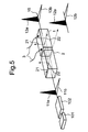
- the large speed polarization modulator which is capable of carrying out the polarization modulation of the sine wave having the bit rate frequency for the optical signal which has suffered the large speed intensity modulation at the bit rate of equal to or larger than 2.5 Gb/s
- the phase modulator employing the LN waveguide can be used as the large speed polarization modulator which is capable of carrying out the polarization modulation of the sine wave having the bit rate frequency for the optical signal which has suffered the large speed intensity modulation at the bit rate of equal to or larger than 2.5 Gb/s.
- the phase modulator may be utilized as the polarization modulator, first of all, the optical signal is made incident in such a way that the optical signal is wave-guided equally to the two polarization axes of the phase modulator. Then, if the electrical signal which is used to carry out the modulation is applied, then the two light beams are subjected to the phase modulation having the different depths due to the difference in the electro-optic coefficient between the two polarization axes of the LN waveguide, so that the polarization state is changed.
- the LN waveguide which is identical in kind and length to the LN waveguide which is employed in the modulation portion is known as such a device which can be most simply prepared.
- the polarization axis (the fast axis) 21, which has the relatively large propagation speed, of the LN waveguide of the modulation portion is coupled to the slow polarization axis (the slow axis) 22, which has the relatively slow propagation speed, of the LN waveguide for compensating for the polarization dispersion
- the slow axis 22 of the LN waveguide of the modulation portion is coupled to the fast axis 21 of the LN waveguide for compensating for the polarization dispersion.
- both of the associated axes are connected to each other at the position where they are twisted by 90 degrees.
- the waveguide for compensating for the polarization dispersion is connected to the position after the waveguide of the modulation portion.
- the two constituent elements may be connected to each other by reversing the order of arrangement of them.
- the polarization dispersion which is in the opposite direction to that of the polarization dispersion occurring in the waveguide for the polarization modulation is previously, intentionally applied to the input optical signal.
- the polarization dispersion in the waveguide for the polarization modulation in the after stage is cancelled out to reduce the degradation of the transmission characteristics due to the influences of the polarization dispersion.
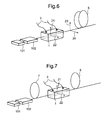
- Fig. 6 is a schematic view showing a construction of the optical transmitter according to the present embodiment.
- the constituent elements which are the same as those shown in Fig. 4 are designated by the same reference numerals.
- Embodiment 1 there has been described the specific case where the LN waveguide which is employed in the modulation portion is utilized as the device for compensating for the polarization dispersion.
- Embodiment 2 a polarization maintaining optical fiber 5 is used as the device for compensating for the polarization dispersion.
- the polarization maintaining optical fiber is an optical fiber which is designed in such a way that the desired stress is intentionally applied between the two polarization axes of the optical fiber to produce the difference in the propagation speed of light, thereby preventing the two polarization components from being coupled to each other.
- This polarization maintaining optical fiber can be used as the birefringence device by making light equally incident to the two polarization axes.
- the difference in the propagation speed of light between the two polarization axes of the present polarization maintaining optical fiber is about on the order of 10 -4 , and hence the delay difference of 15 ps for example can be made possible on the basis of the propagation of 150,000 ps (corresponding to 30 m in length).
- the polarization maintaining optical fiber 5 is connected to the output side of the LN waveguide 1 for the modulation.
- the LN waveguide 1 and the polarization maintaining optical fiber 5 are connected to each other in such a way that the fast axis of the LN waveguide 1 is coupled to the slow axis of the polarization maintaining optical fiber 5, while the slow axis of the LN waveguide 1 is coupled to the fast axis of the polarization maintaining optical fiber 5.
- the length thereof is set in such a way that the polarization dispersion amount which the polarization maintaining optical fiber 5 has is equal to the polarization dispersion amount which the LN waveguide 1 has, thereby preventing the degradation of the transmission characteristics due to the polarization dispersion.
- the polarization maintaining optical fiber 5 for compensating for the polarization dispersion is connected to the output side of the waveguide 1 of the modulation portion.
- another construction may also be adopted in which the polarization maintaining optical fiber 5 for compensating for the polarization dispersion is provided on the input side of the waveguide 1 by reversing the order of the arrangement thereof.
- the optical transmitter of the present embodiment may also be constructed in such a way that the polarization maintaining optical fiber is divided into two portions, i.e., a polarization maintaining optical fibers 7 and 8 which are arranged on both of the sides, i.e., in the preceding stage and the following stage of the LN waveguide 1.
- the total sum of the polarization dispersion amounts of the polarization maintaining optical fibers 7 and 8 is made equal to the polarization dispersion amount of the LN waveguide 1.
- the constituent elements which are the same as those shown in Fig. 6 are designated by the same reference numerals.
- the superposing of the transmission signals is carried out utilizing the intensity modulation.
- the phase modulation may also be adopted instead of the intensity modulation.
- the intensity modulator has only to be replaced with the phase modulator.
- optical transmission system shown in Fig. 8 can be constructed by connecting the above-mentioned optical transmitter 200, optical transmission path 201 and optical receiver 202 to one another.
- a polarization modulator of the present system it is possible to compensate for the polarization dispersion which degrades the transmission characteristics which the conventional polarization modulator essentially has. For this reason, it is possible to prevent the degradation of the transmission characteristics by applying the present polarization modulator to the optical transmitter.
- the polarization modulator of the present system is used in the optical transmitter and also the polarization scrambling is carried out, whereby it is possible to realize the optical transmitter which is capable of suppressing any of the influences of the polarization dependency loss, the polarization hole burning and the polarization dispersion of the polarization dependency effect which degrades the transmission characteristics.
- the polarization maintaining optical fiber as the birefringence device, not only the mounting thereof becomes easy, but also it is possible to realize the optical transmitter which can be readily connected to other devices and which is low in the connection loss and also which is inexpensive.
Landscapes
- Physics & Mathematics (AREA)
- Electromagnetism (AREA)
- Engineering & Computer Science (AREA)
- Computer Networks & Wireless Communication (AREA)
- Signal Processing (AREA)
- Optical Communication System (AREA)
- Optical Integrated Circuits (AREA)
- Optical Modulation, Optical Deflection, Nonlinear Optics, Optical Demodulation, Optical Logic Elements (AREA)
Applications Claiming Priority (2)
| Application Number | Priority Date | Filing Date | Title |
|---|---|---|---|
| JP23564198 | 1998-08-21 | ||
| JP10235641A JP2000066052A (ja) | 1998-08-21 | 1998-08-21 | 偏波変調器及び光送信器 |
Publications (1)
| Publication Number | Publication Date |
|---|---|
| EP0982883A2 true EP0982883A2 (fr) | 2000-03-01 |
Family
ID=16989034
Family Applications (1)
| Application Number | Title | Priority Date | Filing Date |
|---|---|---|---|
| EP19990306521 Withdrawn EP0982883A2 (fr) | 1998-08-21 | 1999-08-18 | Emetteur optique et système de transmission optique |
Country Status (2)
| Country | Link |
|---|---|
| EP (1) | EP0982883A2 (fr) |
| JP (1) | JP2000066052A (fr) |
Cited By (2)
| Publication number | Priority date | Publication date | Assignee | Title |
|---|---|---|---|---|
| KR100621049B1 (ko) | 2004-06-14 | 2006-09-26 | 학교법인연세대학교 | 편광유지 광섬유를 이용한 벡터섬 광위상천이기 |
| CN101819329B (zh) * | 2009-02-27 | 2013-03-13 | 冲电气工业株式会社 | 极化模式色散抑制方法和极化模式色散抑制装置 |
Families Citing this family (3)
| Publication number | Priority date | Publication date | Assignee | Title |
|---|---|---|---|---|
| US7519295B2 (en) * | 2003-10-30 | 2009-04-14 | Tyco Telecommunications (Us) Inc. | Apparatus and method for commissioning an optical transmission system |
| WO2012035613A1 (fr) * | 2010-09-14 | 2012-03-22 | 三菱電機株式会社 | Modulateur de polarisation optique et dispositif de transmission optique |
| JP2013250288A (ja) * | 2012-05-30 | 2013-12-12 | Nippon Telegr & Teleph Corp <Ntt> | 光デバイスおよびその製造方法 |
-
1998
- 1998-08-21 JP JP10235641A patent/JP2000066052A/ja active Pending
-
1999
- 1999-08-18 EP EP19990306521 patent/EP0982883A2/fr not_active Withdrawn
Cited By (2)
| Publication number | Priority date | Publication date | Assignee | Title |
|---|---|---|---|---|
| KR100621049B1 (ko) | 2004-06-14 | 2006-09-26 | 학교법인연세대학교 | 편광유지 광섬유를 이용한 벡터섬 광위상천이기 |
| CN101819329B (zh) * | 2009-02-27 | 2013-03-13 | 冲电气工业株式会社 | 极化模式色散抑制方法和极化模式色散抑制装置 |
Also Published As
| Publication number | Publication date |
|---|---|
| JP2000066052A (ja) | 2000-03-03 |
Similar Documents
| Publication | Publication Date | Title |
|---|---|---|
| US5940196A (en) | Optical communications system with wavelength division multiplexing | |
| US6407845B2 (en) | Optical transmitter and optical transmission system | |
| US5793512A (en) | Optical communication system | |
| EP1060589B1 (fr) | Procede et appareil pour ameliorer le rendement spectral dans des systemes multiplexes en longueur d'onde | |
| EP0792069B1 (fr) | Annulation de composantes de distortion dans une liaison à fibres optiques avec linéarisation à action directe | |
| US7382985B2 (en) | Electrical domain mitigation of polarization dependent effects in an optical communications system | |
| US5946119A (en) | Wavelength division multiplexed system employing optimal channel modulation | |
| US6823141B2 (en) | Optical transmission system and dispersion compensator | |
| EP0643498B1 (fr) | Transmission optique de type non-soliton de capacité hyper-élevée utilisant la conjugaison de phase optique | |
| US5675429A (en) | Optical communication transmission system | |
| US7010231B1 (en) | System and method of high-speed transmission and appropriate transmission apparatus | |
| US20090162059A1 (en) | Wavelength division multiplexing transmission system | |
| US6122086A (en) | Compensation of dispersion | |
| US7796897B2 (en) | WDM optical transmission system and WDM optical transmission method | |
| US20030076567A1 (en) | Efficient optical transmission system | |
| US6626591B1 (en) | Method of reducing intensity distortion induced by cross phase modulation in a WDM optical fiber transmission system | |
| JP2002541720A (ja) | 光学的通信システムにおける偏光モード分散を補償する装置および方法 | |
| US20050013618A1 (en) | Optical receiving method, optical receiver and optical transmission system using the same | |
| EP0982883A2 (fr) | Emetteur optique et système de transmission optique | |
| US6411413B1 (en) | Method and apparatus for performing dispersion compensation without a change in polarization and a transmitter incorporating same | |
| EP1511207A2 (fr) | Procédé et dispositif pour la réduction de la distorsion du second ordre dans des systèmes de communication optique | |
| US6407842B1 (en) | Method and apparatus for transmitting a WDM optical signal having nonuniform channel spacings | |
| US20030152387A1 (en) | Method for transmitting multi-level signals through dispersive media | |
| US6870665B2 (en) | Pumping source with a number of pumping lasers for the raman amplification of a WDM signal with minimized four-wave mixing | |
| US6363181B1 (en) | Method and apparatus for wavelength-division multiplexing |
Legal Events
| Date | Code | Title | Description |
|---|---|---|---|
| PUAI | Public reference made under article 153(3) epc to a published international application that has entered the european phase |
Free format text: ORIGINAL CODE: 0009012 |
|
| AK | Designated contracting states |
Kind code of ref document: A2 Designated state(s): AT BE CH CY DE DK ES FI FR GB GR IE IT LI LU MC NL PT SE |
|
| AX | Request for extension of the european patent |
Free format text: AL;LT;LV;MK;RO;SI |
|
| STAA | Information on the status of an ep patent application or granted ep patent |
Free format text: STATUS: THE APPLICATION HAS BEEN WITHDRAWN |
|
| 18W | Application withdrawn |
Effective date: 20030108 |