EP0982939A2 - Verbesserungen für Filmabtaster - Google Patents
Verbesserungen für Filmabtaster Download PDFInfo
- Publication number
- EP0982939A2 EP0982939A2 EP99306549A EP99306549A EP0982939A2 EP 0982939 A2 EP0982939 A2 EP 0982939A2 EP 99306549 A EP99306549 A EP 99306549A EP 99306549 A EP99306549 A EP 99306549A EP 0982939 A2 EP0982939 A2 EP 0982939A2
- Authority
- EP
- European Patent Office
- Prior art keywords
- light
- film
- diffuser
- collection system
- diffuse
- Prior art date
- Legal status (The legal status is an assumption and is not a legal conclusion. Google has not performed a legal analysis and makes no representation as to the accuracy of the status listed.)
- Withdrawn
Links
Images


Classifications
-
- H—ELECTRICITY
- H04—ELECTRIC COMMUNICATION TECHNIQUE
- H04N—PICTORIAL COMMUNICATION, e.g. TELEVISION
- H04N5/00—Details of television systems
- H04N5/222—Studio circuitry; Studio devices; Studio equipment
- H04N5/253—Picture signal generating by scanning motion picture films or slide opaques, e.g. for telecine
-
- H—ELECTRICITY
- H04—ELECTRIC COMMUNICATION TECHNIQUE
- H04N—PICTORIAL COMMUNICATION, e.g. TELEVISION
- H04N1/00—Scanning, transmission or reproduction of documents or the like, e.g. facsimile transmission; Details thereof
- H04N1/40—Picture signal circuits
- H04N1/409—Edge or detail enhancement; Noise or error suppression
- H04N1/4097—Removing errors due external factors, e.g. dust, scratches
Definitions
- This invention relates to film scanners and the collection of light which has been scattered by blemishes and dirt on the film.
- the invention is particularly applicable to flying spot telecines.
- the scanning of movie film to convert the images into an electrical signal is typified by television telecine scanners such as the URSA series and ADS 2 telecines manufactured by Cintel International Limited of Ware, Hertfordshire, England.
- television telecine scanners such as the URSA series and ADS 2 telecines manufactured by Cintel International Limited of Ware, Hertfordshire, England.
- the techniques used to scan film for television applications employ either rastered light systems, such as may be produced by a Cathode Ray Tube (CRT) and scanning system in conjunction with a photosensitive detector, or use a high intensity light source and solid state sensor such as line array and area array Charge Coupled Devices (CCD).
- CTR Cathode Ray Tube
- CCD Charge Coupled Devices
- Another disadvantage of using a highly collimated light to illuminate the film is that it will also accentuate any surface damage or blemishes on the film such as typified by scratches or fine particle dust. This is because the collimated light encountering a scratch will become scattered by the scratch profile so it does not enter the photo sensor, and when encountering dust particles is cut off from entering the film and is thereby eliminated from reaching the photo sensor, unless there is any diffraction of the light by the film grains. It is a well understood phenomena of the silver halide/dye particles of film that they will, on a microscopic scale, scatter and diffuse the penetrating light on its path through the film and thus proportionately less will be collected by the imaging optics.
- a variety of electronic equipment also exists for processing television, or data, signals to electronically eliminate, or mask, film scratches and dirt.
- This equipment is typified by the Snell & Wilcox NRS500 High Performance Digital Noise Reducer. These devices rely upon combinations of recursive, transversal, and in some cases temporal electronic filters.
- the quality of the scan depends upon a uniform intensity, broad spectral response, rastered light beam generated by a cathode ray tube (CRT) having an accurate temporal: spatial relationship at the film plane since, for a given colour, just one photo sensor is used to detect the light emerging from the film.
- CTR cathode ray tube
- the light through the film must illuminate just one film picture element (pixel) so that the detected light level, in that channel, is a precise measurement of the film pixel's density in that colour.
- the spatial size of the film pixel being determined by the system resolution required.
- a flying spot film scanner or telecine does not use a diffuse light source to analyse the film since the act of diffusing the beam prior to analysing the film would degrade the quality of the temporal: spatial relationship at the film plane i.e. the detected light would produce a density measurement proportional to a multitude of film pixels.
- the CRT light beam needs to be highly focussed prior to illuminating the film.
- the focussed light is specular/collimated in nature. This results in film and/or dirt scratches being visible to the photo sensor. This is because when specular light encounters a film scratch it will normally be scattered by the scratch profile. The exact image consequence of this scattering is dependent upon whether the scratch is in the film substrate, or the film emulsion. In either case the scratch will scatter light away from the photo sensor.
- a telecine system addressing the problem of light scattered by scratches is disclosed in WO 83/02869.
- the telecine includes means for redirecting light scatters by damage to the surface of film towards a photo detector.
- the means for collecting shown is a frusto-conical mirror or other arrangement of mirrors to collect as much light as possible scattered by scratches.
- the visibility of scratches is because of a difference in the intensity of light reaching the detector in comparison to unscratched areas of film, and that the visibility can be reduced not only by increasing the amount of scattered light collected, but also by reducing the difference in intensity between light received from scratched and unscratched areas. This can be done by reducing the intensity of light received from unscratched areas.
- a combination of improving the collection of light from scratched areas, and decreasing the collection of light from unscratched areas will improve the ratio of intensity of light received from scratched areas and unscratched areas reducing scratch visibility.
- the invention provides a film scanner including an optical system for reducing the difference in intensity of light received at a light detector from scratched and unscratched areas of film, in particular by using a diffuser to diffuse both light scattered by scratches and unscattered light.
- a film scanner for producing electrical signals from a film image, comprising: a light source for illuminating film; and a light collection system for directing light modulated by the film to a light detector; and further comprising a diffuser for diffusing light modulated by film arranged to reduce the visibility of imperfections on film, wherein the light collection system is so arranged to image light diffused by the diffuser onto the detector.
- the inclusion of a diffuser with the light collection system has the effect of reducing visibility of scratches.
- the diffuser may be of any diffusing material which by reflection, diffraction, refraction or interference effects diffuses incident light.
- the visibility of scratches is reduced because a greater proportion of scattered light to unscattered light is accepted by the light collection system than if no diffuser were in place.
- the invention also resides in a light collection system for a film scanner for producing electrical signals from a film image, the film scanner comprising: a light source for illuminating film; the light collection system comprising means for directing light modulated by the film to a light detector; and further comprising a diffuser for diffusing light modulated by film arranged to reduce the visibility of imperfections on film, wherein the light collection system is so arranged to image light diffused by the diffuser onto the detector.
- the light collection system and or the diffuser could be provided as an upgrade to an existing telecine.
- the diffuser is preferably so arranged to diffuse light from scratched and unscratched areas of film. This allows light scattered by scratches to be gathered to reduce scratch visibility, and can be achieved by arranging the diffuser to reduce the difference in intensity of light from scratched and unscratched areas of film. To do this, the diffuser is so arranged to increase the collection of light from scratched areas of film, and decrease the collection of light from unscratched areas. In contrast to prior systems in which an attempt is made to collect all light, from scratched or unscratched areas, this preferred feature actually reduces light collected from unscratched areas to make the difference in intensity less and hence reduce the visibility of the scratch.
- the physical arrangement of the diffuser is preferably to diffuse some light from scratched areas of film into the light collection system, and also preferably to diffuse some light from unscratched areas of film outside the light collection system. As a result, the difference in intensities of light from scratched areas and unscratched areas is reduced.
- the diffuser is preferably placed close behind but not immediately adjacent the film, in particular immediately behind a first lens element of the light collection system. This ensures that the diffuser has maximum benefit without the risk that any granularity of the diffuser is imaged on the detector.
- the diffuser may be arranged to diffuse light in 360° in all planes, in less than 360° in all planes or, in particular, in 30° in all planes.
- the wider the diffusion the less visible scratches become but with a decreased (i.e. worsened) signal to noise ration.
- the signal to noise ratio can be restored to an acceptable level by known techniques such as the use of Avalanche Photo Diode detectors which have better Quantum Efficiency than the conventional Photo Multiplier Tubes.
- a diffuser may be arranged accordingly.
- the diffuser is arranged to diffuse light predominantly in one plane.
- the plane in which light is diffused is orthogonal to the predominant scratch direction.
- the diffuser is arranged to diffuse light in a wider angle in one plane than in a perpendicular plane, such as 10° in one plane and substantially 60° in the other.
- This arrangement ensures that light scattered by scratches is diffused so that a portion is redirected back into the collection system, but without significantly affecting light in the other plan which is unscattered, thereby improving the signal to noise ratio and further reducing scratch visibility.
- a basic film scanner will first be described, followed by an improved film scanner incorporating a light collection system incorporating means for directing light to a detector which has been scattered to positions outside an optical system.
- An embodiment of the invention will then be described with reference to the basic film scanner. It should be noted, however, that the invention is applicable to a film scanner, such as a CRT scanner, with either a basic or improved light collection system as described herein.
- a film scanner converts an image stored on film to an image represented by electrical signals.
- a telecine is one type of film scanner which converts the image to a television signal.
- a film scanner or telecine comprises a light source for illuminating film, a film gate for holding and transporting film, imaging optics for directing light modulated by the film to a light detector and an electronic system for manipulating and storing the electrical signals from the detector.
- the types of light source, film gate, detector and electronic system available are well known to the person skilled in the art, and need not be described further here. Suitable examples may, in any case, be found in any of the references noted in the background section above. The following description will concentrate on the imaging optics.
- Fig 1. shows the basic CRT, imaging optics, film gate, light collection optics and photo sensor detector elements of a flying spot scanner or telecine.
- the system shown is a monochrome system but those skilled in the art will appreciate that these principles equally apply to a colour system as taught in the declared background material.
- the CRT 10 generates a light raster which is focussed via imaging optics 20, onto the film 60 held in the film gate 30.
- the film 60 is shown in edge view.
- a condenser lens 40 collects the emerging light from the film 60 and images onto the photo sensor detector 50.
- the silver halide grains and or dyes in the film emulsion cause a degree of scattering of the light at it traverses through the film. For reasons of clarity this is not portrayed in Fig. 1.
- the imaging optics 20 and condenser lens 40 could be implemented by a plurality of lenses, and this is within the knowledge of the skilled person. In fact, for 3-colour scanning further optical elements would be required to split the light modulated by the film into separate components for sensing which, again, is within the knowledge of the skilled person.
- the imaging optics 20 and condenser lens 40 are chosen and arranged such that the condenser lens 40 produces an image of the imaging optics 20 on the photo sensor detector 50.
- the photo sensor detector is a diffuse detector of circular cross section.
- the arrangement shown in Fig. 1 is typically mounted in a casing with an internal substantially non-reflective coating, such as black paint.
- Fig. 2 shows the same basic arrangement as given in Fig. 1, however now the film 60 includes a scratch 80 which causes scattering of the incident light.
- the film 60 includes a scratch 80 which causes scattering of the incident light.
- the condenser lens 40 some of the light rays are so scattered that they fail to be imaged onto the photo sensor detector 50.
- the scratch becomes visible as it forms a further modulation to the light in addition to that caused by the silver halide, and or dye, particles in the film emulsion.
- these lost light rays can be collected, then the visibility of the scratch on the film would be diminished, if not eliminated altogether.
- the Mylar or Acetate surface There are two film surfaces, the Mylar or Acetate surface, and the emulsion surface. Either of these surfaces may incur scratches. If a scratch occurs in the Mylar or Acetate surface then the scattered light rays will illuminate film pixels other than just that determined by the temporal: spatial relationship of the light raster. These scattered rays will therefore cause a muddying of the true value of the pixel being scanned, however since the scattering is on a microscopic scale the scattered rays will illuminate film image pixels adjacent to the correct pixel and will therefore normally be of a related nature. Thus the act of collecting these scattered rays will still lessen the visibility of the scratch. If the scratch occurs on the film emulsion surface then provided the scratch does not totally eliminate the film image i.e.
- the scattered light rays will produce relevant light values when collected and conveyed to the photo sensor detector. Again this will diminish the visibility of the scratch. If the scratch is sufficient to have removed the film image emulsion then the scattering of the light to illuminate adjacent film image pixels will, once these rays are collected, help to mask the scratch, but the scratch remains visible as an imperfection in the detected image.
- the invention is therefore particularly applicable to flying spot scanners, and other scanners where the illuminating spot is image onto the film such as laser scanners and rotating mirror scanners.
- the scanner comprises a light source in the form of a CRT 10 focussed by a lens 20 onto the film 60.
- a light collection system comprises an optical system comprising a plano-convex lens 90, and a further plano-convex lens 100 which image light from the film onto the photo sensor.
- the light collection system also comprises means for directing light shown here as a reflector which may comprise one or more sections, but is preferably a single piece internally highly reflective cylinder 70.
- the principle of operation is that light rays which do not directly couple to lens 90, for example those rays which would have failed to be collected by lens 40 in Fig.
- the typical dimensions are chosen for scanning 35 mm film. Accordingly, the diameter of the cylinder 70, the lens 90 and lens system 100 is around 50 mm.
- the photo sensor 50 could be a similar diameter, but is preferably around 10 mm.
- Clearly lens systems 90 and 100 may be other than the plano convex versions described.
- the cylinder 70 may be constructed from glass, plastic or metal. Although described as a cylinder, the device could be any appropriate reflective surface which increases the quantity of light scattered by imperfections which reaches the film. A square cross section could also be appropriate, as could other polygonal shapes.
- a cylinder offers the advantage of maximising the light directed to the sensor and fits conveniently to the lenses.
- the incident light will have been scattered and diffracted by the grains in the film emulsion and hence be of a diffuse nature such that a significant amount of light will emerge from the film to be collected by the light collection system 70,90, 100 and imaged onto the sensor 50.
- the reflecting cylinder 70, and associated optics 90 and 100 would directly couple between the film gate 30, the entry optics of the red, green, blue light splitter cell box, and throughout the colour splitter box.
- the diameter of the collection lenses 90, 100 and cylinder 70 would ideally be constructed to have as large a diameter as possible for a given application. This rule would also apply to the dichroic splitting mirrors, further optics and sensors.
- FIG. 4 A variation of the arrangement shown in Fig. 3 in which the reflective surface of the cylinder is extended toward the film is shown in Fig. 4. All light scattered by imperfections is useful to reducing the visibility of the imperfections. Accordingly, in this arrangement the part of the reflective surface between the first lens 90 and the film is extended to be as close to the film as possible, perhaps with a gap of a few millimetres.
- the reflective surface of the cylinder is shaped in the region between the imaging optics 100 and the photo sensor 50.
- the shaping is chosen to reduce the cylinder diameter from around 50 mm to the size of the photo sensor of around 10 mm.
- the shaping may be curved, a truncated cone or a series of truncated cones of increasing angle.
- the arrangement described has reflective surfaces for directing light to the photo sensor in 3 regions:
- Appropriate reflectors may be used in each of these regions above, or in combination, and particularly as shown in Figs 3, 4 and 5 alone or in combination.
- the reflector chosen could be diffuse or specular.
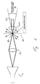
- a film scanner embodying the invention includes a CRT 10, imaging optics 20 and film gate 30 as previously described with reference to figure 1, and shown in part in figure 6.
- the present description concentrates on light collection.
- Light illuminating the film 60 is modulated by the film and imaged onto a detector 50 via imaging optics in the form of a condenser lens 40.
- the present invention may also be embodied in combination with the improved light collections system, in which case the imaging optics 40 will include directing means 70 as shown in figures 3,4 and 5.
- a scratch 80 causes scattering of light so that some of the scattered light is not imaged onto the detector 50 by the light collections system.
- the angle of acceptance of the light collections system is ⁇ steradians.
- the embodiment includes a diffuser 110 which will now be described.
- the diffuser 110 may be any material which by reflection, diffraction, refraction, or interference effects, spreads the energy of an incident light ray into a full solid angle of 4n steradians, or 360° spread in all planes. Suitable material would be ground glass, opal glass, holograms, paper and others.
- a disadvantage of this diffusion is that only the proportion ⁇ /4 ⁇ of light from undamaged areas of film is collected by the collection system , but has the following advantage.
- a compromise can be made by using a material with a diffusion, diffractions or scattering angle less than 360° such as a holographic diffuser or pair of crossed diffraction gratings.
- a material with a diffraction angle similar to the scattering angle range of the scratch allows the most efficient means of sending a fraction of the scattered light into the acceptance angle of the light collection system.
- a preferred 30° diffusion angle material is chosen, such as a holographic diffuser from Edmund scientific, part no H54501.
- the diffuser is matched to the angular scattering range of the scratch.
- the preferred choice of diffuser is a 10°x 60° elliptical holographic diffuser from Edmund scientific, contained in kit part no H53874. When aligned correctly this can greatly reduce the visibility of vertical scratches.
Landscapes
- Engineering & Computer Science (AREA)
- Multimedia (AREA)
- Signal Processing (AREA)
- Facsimile Scanning Arrangements (AREA)
- Light Sources And Details Of Projection-Printing Devices (AREA)
Applications Claiming Priority (6)
| Application Number | Priority Date | Filing Date | Title |
|---|---|---|---|
| GB9818317 | 1998-08-21 | ||
| GBGB9818317.1A GB9818317D0 (en) | 1998-08-21 | 1998-08-21 | Improvements relating to film scanners |
| GBGB9819677.7A GB9819677D0 (en) | 1998-08-21 | 1998-09-09 | Improvements relating to film scanners |
| GB9819677 | 1998-09-09 | ||
| GB9908789 | 1999-04-16 | ||
| GB9908789A GB2343077A (en) | 1998-08-21 | 1999-04-16 | Film scanner using a diffuser to reduce visibility of imperfections on film surface |
Publications (2)
| Publication Number | Publication Date |
|---|---|
| EP0982939A2 true EP0982939A2 (de) | 2000-03-01 |
| EP0982939A3 EP0982939A3 (de) | 2001-09-12 |
Family
ID=27269445
Family Applications (1)
| Application Number | Title | Priority Date | Filing Date |
|---|---|---|---|
| EP99306549A Withdrawn EP0982939A3 (de) | 1998-08-21 | 1999-08-19 | Verbesserungen für Filmabtaster |
Country Status (2)
| Country | Link |
|---|---|
| EP (1) | EP0982939A3 (de) |
| GB (1) | GB2343077A (de) |
Cited By (1)
| Publication number | Priority date | Publication date | Assignee | Title |
|---|---|---|---|---|
| WO2023224482A1 (en) | 2022-05-17 | 2023-11-23 | Felixsonip B.V. | Method for improved scanning of a photographic emulsion |
Families Citing this family (2)
| Publication number | Priority date | Publication date | Assignee | Title |
|---|---|---|---|---|
| GB9826807D0 (en) * | 1998-12-04 | 1999-01-27 | Innovation Tk Limited | Telecine systems |
| US7095646B2 (en) | 2002-07-17 | 2006-08-22 | Freescale Semiconductor, Inc. | Multi-state magnetoresistance random access cell with improved memory storage density |
Family Cites Families (4)
| Publication number | Priority date | Publication date | Assignee | Title |
|---|---|---|---|---|
| US4481414A (en) * | 1982-02-12 | 1984-11-06 | Eastman Kodak Company | Light collection apparatus for a scanner |
| CA1211053A (en) * | 1982-02-12 | 1986-09-09 | Peter B. Watt | Colour scanners |
| US5155596A (en) * | 1990-12-03 | 1992-10-13 | Eastman Kodak Company | Film scanner illumination system having an automatic light control |
| GB2299726B (en) * | 1995-04-07 | 1999-07-28 | Rank Cintel Ltd | Diffusers for film scanners and the like |
-
1999
- 1999-04-16 GB GB9908789A patent/GB2343077A/en not_active Withdrawn
- 1999-08-19 EP EP99306549A patent/EP0982939A3/de not_active Withdrawn
Cited By (1)
| Publication number | Priority date | Publication date | Assignee | Title |
|---|---|---|---|---|
| WO2023224482A1 (en) | 2022-05-17 | 2023-11-23 | Felixsonip B.V. | Method for improved scanning of a photographic emulsion |
Also Published As
| Publication number | Publication date |
|---|---|
| GB2343077A (en) | 2000-04-26 |
| GB9908789D0 (en) | 1999-06-09 |
| EP0982939A3 (de) | 2001-09-12 |
Similar Documents
| Publication | Publication Date | Title |
|---|---|---|
| US5194959A (en) | Image forming apparatus for forming image corresponding to subject, by dividing optical image corresponding to the subject into plural adjacent optical image parts | |
| US4453180A (en) | Light pick-up device | |
| US4481414A (en) | Light collection apparatus for a scanner | |
| US4473848A (en) | Light pick-up device | |
| US5274243A (en) | Cylindrical allumination system for inspection of sheet material | |
| EP0565776B1 (de) | Farbbildaufnahmevorrichtung und -verfahren | |
| JP3118016B2 (ja) | 画像読み取り装置 | |
| US5481381A (en) | Color image reading apparatus | |
| US5523562A (en) | Optical scanner having enhanced depth of illumination | |
| US5673122A (en) | Image reading apparatus including slit member disposed between film original and reading lens | |
| EP0982939A2 (de) | Verbesserungen für Filmabtaster | |
| US5414489A (en) | Light pipe spectral filter | |
| US5847754A (en) | High resolution film scanner/telecine which uses a microlithographic diffuser laminate to aid in the reduction of visibility of surface imperfections in the film | |
| US3624272A (en) | Trichromatic optical separator system using concave dichroic mirrors | |
| CA1211053A (en) | Colour scanners | |
| US4797558A (en) | Inspection apparatus including photodetection and scanning apparatus | |
| JPH058628B2 (de) | ||
| US5815329A (en) | Tri-mirror multi-reflection optical path folding apparatus | |
| JPS6276858A (ja) | 透視オリジナルを走査する際のキヤリエ効果を除去する装置 | |
| US4725729A (en) | Apparatus for correcting unevenness of light quantity in an optical reproduction system | |
| JP2906745B2 (ja) | 表面うねり検査装置 | |
| EP0140529A1 (de) | Abbildungsgerät | |
| GB2323495A (en) | Telecine systems | |
| US3585288A (en) | Projection apparatus for use in an image transducing system | |
| KR0137607B1 (ko) | 광학저역필터(o-lpf)(optical low pass filter) |
Legal Events
| Date | Code | Title | Description |
|---|---|---|---|
| PUAI | Public reference made under article 153(3) epc to a published international application that has entered the european phase |
Free format text: ORIGINAL CODE: 0009012 |
|
| AK | Designated contracting states |
Kind code of ref document: A2 Designated state(s): AT BE CH CY DE DK ES FI FR GB GR IE IT LI LU MC NL PT SE |
|
| AX | Request for extension of the european patent |
Free format text: AL;LT;LV;MK;RO;SI |
|
| PUAL | Search report despatched |
Free format text: ORIGINAL CODE: 0009013 |
|
| AK | Designated contracting states |
Kind code of ref document: A3 Designated state(s): AT BE CH CY DE DK ES FI FR GB GR IE IT LI LU MC NL PT SE |
|
| AX | Request for extension of the european patent |
Free format text: AL;LT;LV;MK;RO;SI |
|
| AKX | Designation fees paid | ||
| REG | Reference to a national code |
Ref country code: DE Ref legal event code: 8566 |
|
| STAA | Information on the status of an ep patent application or granted ep patent |
Free format text: STATUS: THE APPLICATION IS DEEMED TO BE WITHDRAWN |
|
| 18D | Application deemed to be withdrawn |
Effective date: 20020301 |