EP0983203B1 - Total release actuator for an aerosol can - Google Patents
Total release actuator for an aerosol can Download PDFInfo
- Publication number
- EP0983203B1 EP0983203B1 EP98921099A EP98921099A EP0983203B1 EP 0983203 B1 EP0983203 B1 EP 0983203B1 EP 98921099 A EP98921099 A EP 98921099A EP 98921099 A EP98921099 A EP 98921099A EP 0983203 B1 EP0983203 B1 EP 0983203B1
- Authority
- EP
- European Patent Office
- Prior art keywords
- trigger
- actuator
- valve
- total release
- hinge
- Prior art date
- Legal status (The legal status is an assumption and is not a legal conclusion. Google has not performed a legal analysis and makes no representation as to the accuracy of the status listed.)
- Expired - Lifetime
Links
Images


Classifications
-
- B—PERFORMING OPERATIONS; TRANSPORTING
- B65—CONVEYING; PACKING; STORING; HANDLING THIN OR FILAMENTARY MATERIAL
- B65D—CONTAINERS FOR STORAGE OR TRANSPORT OF ARTICLES OR MATERIALS, e.g. BAGS, BARRELS, BOTTLES, BOXES, CANS, CARTONS, CRATES, DRUMS, JARS, TANKS, HOPPERS, FORWARDING CONTAINERS; ACCESSORIES, CLOSURES, OR FITTINGS THEREFOR; PACKAGING ELEMENTS; PACKAGES
- B65D83/00—Containers or packages with special means for dispensing contents
- B65D83/14—Containers for dispensing liquid or semi-liquid contents by internal gaseous pressure, i.e. aerosol containers comprising propellant
- B65D83/16—Actuating means
- B65D83/20—Actuator caps
- B65D83/206—Actuator caps comprising cantilevered actuating elements, e.g. levers pivoting about living hinges
-
- B—PERFORMING OPERATIONS; TRANSPORTING
- B65—CONVEYING; PACKING; STORING; HANDLING THIN OR FILAMENTARY MATERIAL
- B65D—CONTAINERS FOR STORAGE OR TRANSPORT OF ARTICLES OR MATERIALS, e.g. BAGS, BARRELS, BOTTLES, BOXES, CANS, CARTONS, CRATES, DRUMS, JARS, TANKS, HOPPERS, FORWARDING CONTAINERS; ACCESSORIES, CLOSURES, OR FITTINGS THEREFOR; PACKAGING ELEMENTS; PACKAGES
- B65D83/00—Containers or packages with special means for dispensing contents
- B65D83/14—Containers for dispensing liquid or semi-liquid contents by internal gaseous pressure, i.e. aerosol containers comprising propellant
- B65D83/16—Actuating means
-
- B—PERFORMING OPERATIONS; TRANSPORTING
- B65—CONVEYING; PACKING; STORING; HANDLING THIN OR FILAMENTARY MATERIAL
- B65D—CONTAINERS FOR STORAGE OR TRANSPORT OF ARTICLES OR MATERIALS, e.g. BAGS, BARRELS, BOTTLES, BOXES, CANS, CARTONS, CRATES, DRUMS, JARS, TANKS, HOPPERS, FORWARDING CONTAINERS; ACCESSORIES, CLOSURES, OR FITTINGS THEREFOR; PACKAGING ELEMENTS; PACKAGES
- B65D83/00—Containers or packages with special means for dispensing contents
- B65D83/14—Containers for dispensing liquid or semi-liquid contents by internal gaseous pressure, i.e. aerosol containers comprising propellant
- B65D83/16—Actuating means
- B65D83/20—Actuator caps
-
- B—PERFORMING OPERATIONS; TRANSPORTING
- B65—CONVEYING; PACKING; STORING; HANDLING THIN OR FILAMENTARY MATERIAL
- B65D—CONTAINERS FOR STORAGE OR TRANSPORT OF ARTICLES OR MATERIALS, e.g. BAGS, BARRELS, BOTTLES, BOXES, CANS, CARTONS, CRATES, DRUMS, JARS, TANKS, HOPPERS, FORWARDING CONTAINERS; ACCESSORIES, CLOSURES, OR FITTINGS THEREFOR; PACKAGING ELEMENTS; PACKAGES
- B65D83/00—Containers or packages with special means for dispensing contents
- B65D83/14—Containers for dispensing liquid or semi-liquid contents by internal gaseous pressure, i.e. aerosol containers comprising propellant
- B65D83/145—Containers for dispensing liquid or semi-liquid contents by internal gaseous pressure, i.e. aerosol containers comprising propellant with tamper-indicating means, e.g. located in front of nozzle outlets
-
- B—PERFORMING OPERATIONS; TRANSPORTING
- B65—CONVEYING; PACKING; STORING; HANDLING THIN OR FILAMENTARY MATERIAL
- B65D—CONTAINERS FOR STORAGE OR TRANSPORT OF ARTICLES OR MATERIALS, e.g. BAGS, BARRELS, BOTTLES, BOXES, CANS, CARTONS, CRATES, DRUMS, JARS, TANKS, HOPPERS, FORWARDING CONTAINERS; ACCESSORIES, CLOSURES, OR FITTINGS THEREFOR; PACKAGING ELEMENTS; PACKAGES
- B65D83/00—Containers or packages with special means for dispensing contents
- B65D83/14—Containers for dispensing liquid or semi-liquid contents by internal gaseous pressure, i.e. aerosol containers comprising propellant
- B65D83/16—Actuating means
- B65D83/24—Arrangements for keeping the actuating means in the active position, e.g. for continuous dispensing
Definitions
- This invention relates to actuators for aerosol cans and, in particular, to actuators that, once activated, are locked in the actuating position, allowing the entire contents of the aerosol can to be released without further action by the user.
- Such total release actuators are commonly used in insecticide fogger products and with other products that are intended to be used as a single, large discharge rather than as a series of separate bursts.
- Emmerson et al. U.S. Pat. No. 4,428,509
- the Emmerson et al. device snaps onto the valve cup rim.
- the device has a trigger hingedly mounted in an actuator body.
- the trigger is depressed by the user, activating the valve by pressure exerted downwardly against the valve stem.
- the body has a projecting latch that is presented toward that end of the trigger which is distant from the hinge. When the trigger is depressed, the latch snaps over a cooperating structure on the end of the trigger, locking the trigger in the down position.
- LaWare et al. U.S. Pat. No. 5,503,303
- LaWare et al. U.S. Pat. No. 5,503,303
- LaWare et al. U.S. Pat. No. 5,503,303
- LaWare et al. U.S. Pat. No. 5,503,303
- LaWare et al. U.S. Pat. No. 5,503,303
- LaWare et al., U.S. Pat. No. 5,503,303 utilizes a sliding panel that engages a valve stem.
- the actuator is used by thrusting the panel horizontally, which motion moves the valve stem to the side, activating it.
- Detents in the cap interact with the structures on the moving panel to lock it into the on position.
- the LaWare et al. device attaches to the chime of the can.
- the chime is that joint formed between the body of the can and the generally dome-shaped structure that supports the valve cup.
- the art includes a number of designs for locking actuators that employ a button-type structure that is depressed directly downwardly to actuate a vertical push-type valve, the button then being locked in the downward, activating position. See, for example, Yamada et al., U.S. Pat. No. 3,804,303; Sette, U.S. Pat. No. 3,844,448; White, U.S. Pat. No. 4,186,853; Barlics, U.S. Pat. No. 4,277,004; Sette et al., U.S. Pat. No. 3,729,120; and Sagarin, U.S. Pat. No. 3,519,173. Gailitis, U.S. Pat. No. 4,260,080, shows a device that is supported solely by the valve stem and is adapted for use with a tilt stem valve.
- the Emmerson et al. actuator trigger arm locks in the down position by the action of a single spur, shown at 52 in the Emmerson et al. figures, which extends from the body of the actuator to engage a ledge 54 on the actuator trigger. Breakage or other mechanical failure of the single spur 52 results in a non-operable total release actuator. Furthermore, if the entire Emmerson et al. actuator is flexed by being squeezed from side to side, the ledge 54 tends to be drawn away and out from under the spur 52 to release the button 26, interrupting the dispensing of the contents of the aerosol can.
- the art still is in need of a reliable total release actuator having a stem socket that reliably engages the valve stem through the entire swing of the trigger arm and being less subject to failure by distortion of the actuator or by mechanical failure of single locking devices.
- the invention which is as defined in claim 1 below provides a total release actuator for use with an aerosol can having a chime, a dome, and a valve having a valve stem.
- the actuator has an actuator body having a peripheral skirt that extends downwardly, the lower margin of the peripheral skirt defining a skirt rim.
- the actuator is adapted to attach to the aerosol can, and preferably the skirt rim is adapted to attach to the aerosol can.
- the actuator body has a central well having a generally horizontal well floor.
- the well floor has a trigger port extending therethrough, the trigger port having a front end, a back end, and opposed sides.
- the actuator has a longitudinally extended trigger having a front end, a back end, and sides.
- the trigger is attached at one of its front and back ends to the corresponding end of the trigger port by a hinge.
- the hinge allows the end of the trigger that is remote from the hinge to swing downwardly when the trigger is depressed, the trigger extending from the hinge across the valve stem when the actuator is in place on the aerosol can.
- the trigger is so attached at its front end to the front end of the trigger port.
- the hinge allows the trigger's back end to swing downwardly when the trigger is depressed.
- the trigger extends across the valve stem when the actuator is in place on the aerosol can and includes a downwardly open stem socket that is adapted to receive the valve stem.
- the stem socket is in fluid communication with a discharge nozzle. The trigger, when moved downwardly, activates the valve by exerting pressure on the valve stem, releasing the contents of the can through the discharge nozzle via the stem socket.
- the actuator further includes two elastically deformable latches each attached to one of a side of the trigger port and a side of the trigger and adapted to engage the other of the side of the trigger port and the side of the trigger when the trigger is in a depressed, valve-activating position to retain the trigger in that position.
- the latches are attached to one of the sides of the trigger port and extends laterally under the trigger. When so attached to the trigger port, the latch first flexes sidewardly, allowing the trigger to pass as it is depressed by a user downwardly beyond the latch to a valve-activating position. Then the latch springs back over the trigger to retain it in the valve-activating position, allowing can contents to discharge. By this means, a user can release the entire contents of the aerosol can without the user's having to continue to depress the trigger.
- the total release actuator includes two latches, one extending from each of the opposed sides of the trigger port, to retain the trigger under and between the latches when a user has depressed the trigger downwardly beyond the latches to the valve-activating position.
- the latches are located beneath the level of the well floor.
- the trigger includes a push pad, on which a user can push to depress the trigger.
- the trigger further includes a downwardly extended drop side that has upwardly presented lugs. As the trigger is depressed to the valve-activating position, the lugs move beneath and then engages the respective latch, locking the trigger in the valve-activating position.
- the latches are located sufficiently far beneath the well floor that the trigger reaches its valve-activating position before the finger of a user, pressing on the push pad, makes contact with the latch.
- skirt rim can be attached to the valve cup rim of the can, it is preferred that the skirt rim be adapted to engage and, preferably, attach to the chime of the aerosol can, that the hinge be distal to the valve cup rim when the actuator is in place on the can, and that the trigger include a push pad remote from the hinge, with the stem socket being located between the hinge and the push pad.
- the total release actuator of the invention includes a tear tab attached by attachment members to both the end of the trigger remote from the hinge and the corresponding end of the trigger port remote from the hinge.
- the tear tab and attachment members have a robustness and strength such that the tear tab stabilizes the trigger to reduce the chance of premature activation.
- the attachment members break, allowing the tear tab to be removed, leaving the trigger free to be depressed.
- the attachment members are shaped so as to break preferentially at a point remote from the tear tab. This causes the attachment members, when the tear tab is torn away, to break free from the trigger and the back end of the trigger port and remain attached to the tear tab.
- the peripheral skirt extends upwardly above the level of the well floor
- the central well has a well wall that extends upwardly from the margins of the well floor and is joined to the upper margin of the peripheral skirt to form a double-walled, hollow bracing structure.
- the actuator includes, in combination, the bracing structure, well floor, and chime-engaging skirt rim disclosed, which coact to increase the resistance of the actuator body to lateral flexing. As a result, the reliability of the latch's retention of the trigger in the valve actuating position is improved.
- the invention also includes a method for total release of the contents of an aerosol can as set out in claim 11 below.
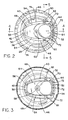
- Fig. 1 shows the preferred embodiment of the total release actuator of the invention, shown generally at 10
- the total release actuator 10 is adapted for use with a conventional aerosol can, such as that shown in phantom at 12 in Fig. 4.
- aerosol cans 12 include a cylindrical can wall 14 that is closed at its upper margin by a dome 16.
- the joint between the upper margin of the can wall 14 and the dome 16 is referred to as the can chime 18.
- a valve cup 20 is located at the center of the dome 16 and is joined to the dome by a joint that is referred to as the valve cup rim 22.
- a valve 24 is located at the center of the valve cup 20.
- the valve 24 has an upwardly extending valve stem 26, through which the contents of the can may be expelled.
- Valves 24 typically are either vertically actuated valves, which are opened by moving the valve stem 26 directly downwardly, or side-tilt valves. A side-tilt valve is actuated by tipping the valve stem laterally.
- the total release actuator 10 has an actuator body 28 adapted to attach to the aerosol can 12.
- the actuator body 28 has a peripheral skirt 30.
- the lower margin of the peripheral skirt 30 defines a skirt rim 32.
- the skirt rim 32 is adapted to fit over and engage the chime 18.
- the skirt rim 32 shall be understood to "engage” the chime 18 if it contacts the chime in such a manner as to be laterally braced against it.
- the skirt rim 32 actually attaches to the chime 18 by means of undercuts 34 that extend inwardly from the interior surface of the skirt rim.
- the actuator body 28 is forced downwardly onto the chime 18, the undercuts 34 slipping over the chime to snap under it, fastening the actuator body to the chime.
- the advantage of this point of engagement or attachment will be discussed below.
- the actuator body 28 also has a central well 36.
- the central well 36 preferably has a generally horizontal well floor 38, best shown in Figs. 1 and 2.
- the central well 36 has a trigger port 40, preferably located in and extending through the well floor 38.
- the trigger port 40 has a front end 42, a back end 44, and opposed sides 46.
- the total release actuator 10 of the invention includes a longitudinally extended trigger 48.
- the trigger 48 has a front end 50, a back end 52, and sides 54.
- the trigger 48 is attached at one of its front and back ends 50,52 to the corresponding front or back end 42,44 of the trigger port 40. This attachment is by means of a hinge 56, which most conveniently is a living hinge that is unitarily molded with the remaining parts of the total release actuator 10.
- the trigger 48 is attached at its front end 50 to the front end 42 of the trigger port 40, as is shown in the figures, to allow the trigger's back end 52 to swing downwardly when the trigger is depressed.
- the hinge 56 allows the end of the trigger 48 that is remote from the hinge to swing downwardly when the trigger is depressed.
- the trigger 48 extends from the hinge 56 across the valve stem 26 when the actuator is in place on the aerosol can 10. This relationship is best shown in Fig. 4.
- the trigger 48 further includes a downwardly open stem socket 58, shown in Figs. 3 and 4.
- the stem socket 58 is adapted to receive the valve stem 26 and is in fluid communication with a discharge nozzle 60.
- the trigger 48 when moved downwardly, activates the valve 24 by exerting pressure on the valve stem 26 to release the contents of the can 10 through the discharge nozzle 60 via the stem socket 58.
- the total release actuator 10 of the invention further includes a latch 62 that preferably is elastically deformable.
- the latch 62 is attached to one of a side 46 of the trigger port 40 and a side 54 of the trigger 48.
- the latch 62 is adapted to engage the other of the side 46 of the trigger port 40 and the side 54 of the trigger 48 when the trigger is in a depressed, valve-activating position to retain the trigger in that position.
- the trigger 48 moves the valve stem 26 sufficiently to activate the valve 24.
- the latch 62 is attached to a side 46 of the trigger port 40 and that, before the total release actuator 10 is activated, the latch 62 extends laterally under the trigger 48, as is best seen in Figs. 3 and 5.
- the latch 62 when the trigger 48 is depressed by a user, the latch 62 first flexes sidewardly, allowing the trigger 48 to pass downwardly beyond the latch to the valve-activating position.
- the latch 62 When the trigger 48 has reached the valve-activating position, the latch 62 then springs back over the trigger to retain the trigger in the valve-activating position.
- the total-release actuator 10 includes two latches 62.
- one latch 62 extends from each of the opposed sides 46 of the trigger port 40, although location of the latches on opposed sides 54 of the trigger 48 is also possible.
- the two latches 62 retain the trigger 48 under and between the latches when a user has depressed the trigger downwardly between them to the valve-activating position.
- This arrangement in combination with other features of the total-release actuator 10 discussed below, leads to a more reliable and trouble-free retention of the trigger 48 when the actuator is used.
- the latch 62 is located beneath the level of the well floor 38.
- the trigger 48 includes a push pad 64 on which a user can push to depress the trigger.
- the push pad 64 may be a surface specially shaped to comfortably receive the user's finger without slipping off the trigger 48, as is the push pad shown in the Figures. However, any surface may be made available for a user to push on to move the trigger 48.
- the trigger 48 preferably also includes a downwardly extended drop side 66.
- the drop side 66 has an upwardly presented lug 68, the drop side and lug being best shown in Fig. 5.
- the lug 68 moves beneath and then engages the latch 62 when the trigger 48 is depressed to the valve activating position.
- the latch 62 is located sufficiently far beneath the well floor 38 that the trigger 48 reaches its valve-activating position before the finger of a user, pressing on the push pad 64 has the opportunity to contact the latch.
- the hinge 56 is located at a point not less distal to the valve stem 26 than the valve cup rim 22, when the actuator is in place on the can 12.
- the push pad 64 is located at a point remote from the hinge 56, and the stem socket 58 is located between the hinge and the push pad.
- This arrangement is relatively difficult to achieve with a valve cup rim 22 attachment of the actuator 10, which is one of the reasons why attachment at the chime 18 is preferred. That hinge location makes possible a trigger 48 of extended length when compared to a trigger hinged at a point within the valve cup rim 22, providing a more advantageous lever arm length.
- One advantage of the preferred hinge location is that it makes it easier for a user to activate the valve 24 simply because of the mechanical advantage of the longer lever arm. But beyond that, the arrangement allows the stem socket 58 to be further from the hinge 56 than would be the case if the hinge had to be within the circuit of the valve cup rim 22. Consequently, the stem socket 58 can be moved downwardly far enough to activate the valve 24 without the stem socket's swinging as far out of axial alignment with the valve stem 26 as would be the case if the hinge had to be located within the valve cup rim 22. This allows for a more reliable engagement of the valve stem 26 within the stem socket 58, with less leaking and a reduced malfunction rate.
- the actuator 10 includes a tear tab 70 that is unitarily molded with the trigger 48 and the actuator body 28.
- the tear tab 70 is attached by attachment members 72 to both the end of the trigger 48 that is remote from the hinge 56 and the end of the trigger port 40 remote from the hinge.
- the hinge 56 is located at the front end 42 of the trigger port 40
- the tear tab 70 is located at the back end 44 of the trigger port.
- the tear tab 70 and attachment members 72 are of a robustness and strength such that the tear tab stabilizes the trigger 48 while the tear tab is in place, reducing the chance of premature activation. However, when a user intentionally and forcibly moves the tear tab 70, the attachment members 72 break, allowing the tear tab to be removed and leaving the trigger 48 free to be depressed.
- the tear tab 70 and attachment members 72 are best shown in Figs. 2-4.
- the attachment members 72 are shaped so as to break preferentially at a point remote from the tear tab 70 and immediately adjacent to the remaining structure to which they are attached, be it the trigger 48 or the adjacent surface of the trigger port 40.
- This arrangement causes the attachment members 72, when the tear tab 70 is torn away, to break free from the trigger 48 and adjacent surface of the trigger port 40 and remain attached to the tear tab. This arrangement leaves the trigger 48 and trigger port 40 free of any remnant of an attachment member 72 that might otherwise be unsightly or uncomfortable to the finger.
- the peripheral skirt 30 of the actuator 10 extends upwardly beyond the level of the well floor 38, and a well wall 74 extends upwardly from the outer margins of the well floor.
- the well wall 74 is best illustrated in Figs. 1, 2, and 4.
- the well wall 74 is joined to the upper margin of the peripheral skirt 30 to form a double-walled, hollow bracing structure 76, best illustrated in Fig. 4.
- the bracing structure 76 extends peripherally around the central well 36, preferably for at least half and more preferably for at least 3/4 of its circumference.
- a finger gap 78 is left as an opening in the bracing structure 76 to allow a user easy access to the push pad 64.
- the tear tab 70 may be designed to substantially fill the finger gap 78, further reducing the likelihood of accidental premature activation prior to removal of the tear tab.
- the bracing structure 76, well floor 78, and chime-engaging skirt rim 32 all coact to achieve a rigidity with respect to lateral compression that, taken together with the side location of the latches 62, is important to the successful operation of the actuator 10.
- An end-mounted latching arrangement such as that seen in Emerson et al., U.S. Pat. No. 4,428,509, has important disadvantages. Because there is only one latch, any failure of that latch causes the trigger to be released from its actuating position and the actuator to malfunction. Simply having two latches 62 provides a backup.
- Utilizing a pair of latches 62 reliably ensures that at least one latch will remain in position to lock the trigger 48 in its actuating position, once the trigger has been depressed, in that any movement of the trigger away from one latch automatically moves it toward the other latch. Furthermore, locating the latches 62 at the sides of the trigger 48 inevitably places them more centrally within the actuator 10. Consequently, the effects of peripheral distortion of the actuator are reduced, by simple geometry--a large distortion at the periphery still results in a reduced distortion at a radially interior position.
- the preferred form of the total release actuator 10 includes the hollow-walled bracing structure 76 described above. This can be contrasted to the solid, otherwise visually corresponding structure of the Emerson et al. device. Not only is the bracing structure 76 itself fairly rigid because of its hollow-walled structure, but the well floor 38 provides further bracing. Consequently, the whole structure resists lateral deformation, whether lateral pressures are applied from side-to-side or from front-to-rear, again increasing the reliability with which the latches 62 extend over and retain the trigger 48 when it has been depressed to its valve actuating position.
- the engagement and, preferably, the attachment of the skirt rim 32 to the chime 18 of the can 12 adds a further mechanism for resisting distortion.
- the can chime 18 is itself rigid, providing a secure form that maintains the shape of the skirt rim 32 when it is engaged with the chime.
- a multiplicity of vertical side braces 80 extend upwardly from the skirt rim 32 toward the level of the well floor 38, the side braces 80 projecting radially from the lower part of the peripheral skirt 30.
- the side braces 80 rise from a brace floor 82 formed in the skirt 30, the brace floor preferably resting upon the can chime 18 when the actuator 10 is in place upon the can 12.
- the brace floor 82 preferably is substantially horizontal and in any event is less than vertical.
- the side braces 80 and adjacent portions of the peripheral skirt 30 effectively transmit the rigidity of the chime-stabilized skirt rim 32 to the lower portion of the bracing structure 76.
- the interaction of the brace floor 82 and side braces 80, in conjunction with the remaining adjacent portions of the peripheral skirt 30, also specifically strengthen the lower part of the actuator body 28 in such a manner as to resist both lateral forces and top loading applied to the actuator body 28.
- the method of the invention for total release of the contents of an aerosol can 10 includes the step of providing a total release actuator 10 made in accordance with the disclosure set forth, above, and attaching the total release actuator to the aerosol can, preferably with the skirt rim 32 engaging the chime 18.
- a subsequent step of the method is to depress the trigger 48 by manual pressure until the latch 62 engages the trigger to retain it in its valve-actuating position. Then the can 12 is left undisturbed until the can's contents are discharged.
- the total release actuator of the invention may be conveniently manufactured from any suitable plastic by standard injection-molding techniques well known to those skilled in the art. All of the parts described can be unitarily molded as a single part, requiring no assembly prior to attachment to the can.
- Total release actuators have application in the insect control industry as well as with any aerosol product intended to be delivered in a large, single spray.
- the actuator of the invention may be manufactured by conventional plastic molding techniques from conventional plastics well known to those skilled in the art.
Landscapes
- Chemical & Material Sciences (AREA)
- Dispersion Chemistry (AREA)
- Engineering & Computer Science (AREA)
- Mechanical Engineering (AREA)
- Containers And Packaging Bodies Having A Special Means To Remove Contents (AREA)
- Nozzles (AREA)
Applications Claiming Priority (3)
| Application Number | Priority Date | Filing Date | Title |
|---|---|---|---|
| US08/854,313 US5791524A (en) | 1997-05-12 | 1997-05-12 | Total release actuator for an aerosol can |
| US854313 | 1997-05-12 | ||
| PCT/US1998/009534 WO1998051588A1 (en) | 1997-05-12 | 1998-05-11 | Total release actuator for an aerosol can |
Publications (2)
| Publication Number | Publication Date |
|---|---|
| EP0983203A1 EP0983203A1 (en) | 2000-03-08 |
| EP0983203B1 true EP0983203B1 (en) | 2002-07-31 |
Family
ID=25318338
Family Applications (1)
| Application Number | Title | Priority Date | Filing Date |
|---|---|---|---|
| EP98921099A Expired - Lifetime EP0983203B1 (en) | 1997-05-12 | 1998-05-11 | Total release actuator for an aerosol can |
Country Status (21)
| Country | Link |
|---|---|
| US (1) | US5791524A (pt) |
| EP (1) | EP0983203B1 (pt) |
| KR (1) | KR100355541B1 (pt) |
| CN (1) | CN1094875C (pt) |
| AR (1) | AR011736A1 (pt) |
| AT (1) | ATE221501T1 (pt) |
| AU (1) | AU730808B2 (pt) |
| BR (1) | BR9809808A (pt) |
| CA (1) | CA2289513C (pt) |
| DE (1) | DE69806926T2 (pt) |
| EG (1) | EG21614A (pt) |
| ES (1) | ES2177007T3 (pt) |
| HU (1) | HUP0002725A3 (pt) |
| ID (1) | ID21420A (pt) |
| NZ (1) | NZ500869A (pt) |
| PL (1) | PL336792A1 (pt) |
| PT (1) | PT983203E (pt) |
| RU (1) | RU2184689C2 (pt) |
| TW (1) | TW443982B (pt) |
| WO (1) | WO1998051588A1 (pt) |
| ZA (1) | ZA983994B (pt) |
Families Citing this family (61)
| Publication number | Priority date | Publication date | Assignee | Title |
|---|---|---|---|---|
| US5906046A (en) * | 1997-07-31 | 1999-05-25 | Precision Valve Corporation | Aerosol tilt valve and method of forming same |
| US6564977B2 (en) * | 1998-12-28 | 2003-05-20 | Yoshino Kogyosho Co., Ltd. | Cap for mounting on aerosol container |
| EP1268306B1 (en) * | 2000-02-02 | 2011-06-29 | Seaquist Perfect Dispensing Foreign, Inc. | Inverted aerosol dispenser |
| GB0016123D0 (en) | 2000-07-01 | 2000-08-23 | Glaxo Group Ltd | Valve for aerosol container |
| US6551001B2 (en) | 2001-09-14 | 2003-04-22 | S. C. Johnson & Son, Inc. | Cleaning device with a trigger-actuated spray canister |
| US6758412B2 (en) | 2001-09-14 | 2004-07-06 | S.C. Johnson & Son, Inc. | Overcap for use with a cleaning device |
| US6588627B2 (en) | 2001-10-31 | 2003-07-08 | S.C. Johnson & Son, Inc. | Automatic intermittent aerosol dispensing valve |
| US6688492B2 (en) * | 2002-01-24 | 2004-02-10 | S.C. Johnson & Son, Inc. | Dispensing valve |
| US6612464B2 (en) | 2001-11-13 | 2003-09-02 | S. C. Johnson & Son, Inc. | Aerosol dispensing valve |
| US6926172B2 (en) * | 2001-10-31 | 2005-08-09 | S. C. Johnson & Son, Inc. | Total release dispensing valve |
| KR20040088586A (ko) * | 2002-03-14 | 2004-10-16 | 시게루 마쓰야마 | 스프레이 캔 및 스프레이 캔의 압력방출구조 |
| US8011363B2 (en) * | 2002-06-03 | 2011-09-06 | Mark Johnson | Exhalation valve for use in a breathing device |
| US7793656B2 (en) | 2002-06-03 | 2010-09-14 | Lifetime Products, Inc. | Underwater breathing devices and methods |
| US7882990B1 (en) | 2002-07-22 | 2011-02-08 | Seaquistperfect Dispensing Foreign, Inc. | Inverted aerosol dispenser |
| US7137536B2 (en) * | 2002-07-22 | 2006-11-21 | Seaquist Perfect Dispensing Foreign, Inc. | Inverted aerosol dispenser |
| GB0220023D0 (en) * | 2002-08-29 | 2002-10-09 | Reckitt Benckiser Inc | Improvements in and to dispensing devices |
| GB0219996D0 (en) * | 2002-08-29 | 2002-10-09 | Reckitt Benckiser Inc | Improvemnts in and to dispensing devices |
| ITRM20030046U1 (it) * | 2003-03-04 | 2004-09-05 | Emsar Spa | Copertura per tasto erogatore di micropompe nebulizzatrici o dispensat rici. |
| US6971557B2 (en) * | 2003-06-19 | 2005-12-06 | S. C. Johnson & Son, Inc. | Actuator for a pressurized material dispenser |
| US7246722B2 (en) * | 2004-04-13 | 2007-07-24 | Seaquist Perfect Dispensing Foreign | Bottom dispensing aerosol device |
| US6971560B1 (en) * | 2004-05-14 | 2005-12-06 | S. C. Johnson & Son, Inc. | Friction resistant time delay actuator assembly for aerosol containers |
| US7213728B2 (en) * | 2004-06-24 | 2007-05-08 | S.C. Johnson & Son, Inc. | Time delay and indicator actuator assembly for aerosol containers |
| US7195139B2 (en) * | 2004-06-29 | 2007-03-27 | S.C. Johnson & Son, Inc. | Dispensing valve |
| US7708173B2 (en) * | 2004-09-08 | 2010-05-04 | Kevin Bromber | Self-orienting aerosol apparatus and method of cleaning a trash can |
| US7823585B2 (en) * | 2004-10-08 | 2010-11-02 | Mark Johnson | Snorkel clip |
| US20080099012A1 (en) * | 2004-10-08 | 2008-05-01 | Johnson Mark R | Snorkel clip |
| CN102616480B (zh) | 2004-10-12 | 2014-12-10 | 约翰逊父子公司 | 一种操作分配单元的方法 |
| US8061562B2 (en) | 2004-10-12 | 2011-11-22 | S.C. Johnson & Son, Inc. | Compact spray device |
| TWI355357B (en) * | 2005-01-26 | 2012-01-01 | Fumakilla Ltd | Head cap for aerosol type atomizer |
| US8297318B2 (en) * | 2005-05-21 | 2012-10-30 | Mark Johnson | Check valve |
| FR2904296A1 (fr) * | 2006-07-27 | 2008-02-01 | Oreal | Dispositif de conditionnement et de distribution d'un produit sous pression |
| US20080099516A1 (en) * | 2006-10-31 | 2008-05-01 | Lacoste Brian O | Extended discharge tube for total release actuators |
| US7699190B2 (en) * | 2007-01-04 | 2010-04-20 | Precision Valve Corporation | Locking aerosol dispenser |
| MX2009008907A (es) * | 2007-02-20 | 2009-10-12 | Mark R Johnson | Valvula de exhalacion para uso en dispositivo respirador submarino. |
| US8590743B2 (en) | 2007-05-10 | 2013-11-26 | S.C. Johnson & Son, Inc. | Actuator cap for a spray device |
| US8556122B2 (en) | 2007-08-16 | 2013-10-15 | S.C. Johnson & Son, Inc. | Apparatus for control of a volatile material dispenser |
| US8469244B2 (en) | 2007-08-16 | 2013-06-25 | S.C. Johnson & Son, Inc. | Overcap and system for spraying a fluid |
| US8381951B2 (en) | 2007-08-16 | 2013-02-26 | S.C. Johnson & Son, Inc. | Overcap for a spray device |
| USD576874S1 (en) | 2007-08-24 | 2008-09-16 | S.C. Johnson & Son, Inc | Actuator cap |
| BRPI0815844B1 (pt) * | 2007-08-28 | 2019-12-10 | Meadwestvaco Calmar Inc | dispensador, e, método para prender uma válvula em um recipiente |
| US8376192B2 (en) | 2008-03-24 | 2013-02-19 | Mary Kay Inc. | Apparatus for dispensing fluids using a press-fit diptube |
| US8387827B2 (en) | 2008-03-24 | 2013-03-05 | S.C. Johnson & Son, Inc. | Volatile material dispenser |
| USD636668S1 (en) | 2008-03-24 | 2011-04-26 | Mary Kay Inc. | Dip tubes |
| US9789502B2 (en) | 2008-06-05 | 2017-10-17 | Mary Kay Inc. | Apparatus for dispensing fluids using a removable bottle |
| WO2009152112A1 (en) * | 2008-06-10 | 2009-12-17 | Meadwestvaco Corporation | Aerosol acctuation systems and methods for making the same |
| US8267286B2 (en) * | 2009-08-03 | 2012-09-18 | Smrt Thomas M | Spray can actuator cap |
| USD627224S1 (en) | 2009-10-08 | 2010-11-16 | S.C. Johnson & Son, Inc. | Overcap |
| US20110303664A1 (en) * | 2010-06-04 | 2011-12-15 | Brian Nichols | Trash can fogger |
| IT1400715B1 (it) * | 2010-07-06 | 2013-06-28 | Capsol S P A | Tappo di azionamento e di erogazione accoppiabile con una bomboletta aerosol. |
| WO2012006532A1 (en) * | 2010-07-08 | 2012-01-12 | The Procter & Gamble Company | Device for dispensing material |
| US8459508B2 (en) * | 2010-07-30 | 2013-06-11 | S.C. Johnson & Son, Inc. | Shroud for a dispenser |
| USD668151S1 (en) | 2010-11-26 | 2012-10-02 | S.C. Johnson & Son, Inc. | Container with retaining device |
| USD700514S1 (en) | 2011-07-29 | 2014-03-04 | S.C. Johnson & Son, Inc. | Container with retaining device |
| AU2012244226B1 (en) * | 2011-11-03 | 2012-12-06 | Subpro Pty Ltd | Aerosol Activator |
| US9108782B2 (en) | 2012-10-15 | 2015-08-18 | S.C. Johnson & Son, Inc. | Dispensing systems with improved sensing capabilities |
| US9540164B1 (en) | 2014-06-17 | 2017-01-10 | S. C. Johnson & Son, Inc. | Time-delay actuator assembly for an aerosol container |
| US9511927B1 (en) | 2014-06-17 | 2016-12-06 | S. C. Johnson & Son, Inc. | Time-delay actuator assembly for an aerosol container |
| DE102016008785A1 (de) * | 2016-07-22 | 2018-01-25 | Beiersdorf Ag | Sprühkappe für Aerosoldruckgaspackungen |
| AU2018238194A1 (en) * | 2017-03-22 | 2019-09-26 | Trouperdale Pty Ltd | An actuator cap |
| US10883610B1 (en) | 2019-07-01 | 2021-01-05 | Chung Ji Hsiao | Fluid actuation system |
| KR102624603B1 (ko) * | 2023-01-05 | 2024-01-12 | 남방씨.엔.에이 주식회사 | 에어로졸 용기용 일체형 분무 캡 조립체 |
Family Cites Families (19)
| Publication number | Priority date | Publication date | Assignee | Title |
|---|---|---|---|---|
| US2910391A (en) * | 1954-07-28 | 1959-10-27 | Ohio Commw Eng Co | Method of applying aerosol detergent fog |
| BE629208A (pt) * | 1962-03-08 | |||
| US3137414A (en) * | 1962-06-14 | 1964-06-16 | Eastern Cap And Closure Compan | Aerosol can assembly and the activator cap for completely dispensing the contents |
| US3305144A (en) * | 1965-03-01 | 1967-02-21 | Valve Corp Of America | Dispenser for disposable aerosol container, with valved conduit for remote dischargeof its contents |
| US3519173A (en) * | 1968-02-13 | 1970-07-07 | Valve Corp Of America | Self-holding actuator cap for aerosol dispensers |
| JPS5122340Y2 (pt) * | 1971-03-31 | 1976-06-09 | ||
| US3729120A (en) * | 1971-05-11 | 1973-04-24 | Sterling Drug Inc | Childproof relockable actuator overcap |
| US3844448A (en) * | 1972-04-27 | 1974-10-29 | J Sette | Valve actuating safety cap assembly for pressurized dispensers |
| US3920162A (en) * | 1974-07-17 | 1975-11-18 | Eiichi Kimura | Apparatus for discharging residual gas in aerosol cans |
| US4186853A (en) * | 1979-01-22 | 1980-02-05 | Summit Packaging Systems, Inc. | Continuous aerosol device |
| US4277004A (en) * | 1979-10-15 | 1981-07-07 | Barlics John J | Cover and aerosol activator for aerosol spray can |
| US4260080A (en) * | 1980-01-18 | 1981-04-07 | Summit Packaging Systems, Inc. | Continuous spray device for aerosol valves |
| GR74502B (pt) * | 1980-05-30 | 1984-06-28 | Oreal | |
| US4381065A (en) * | 1981-05-29 | 1983-04-26 | Precision Valve Corporation | Continuous discharge aerosol actuator |
| US4428509A (en) * | 1982-04-01 | 1984-01-31 | S. C. Johnson & Sons, Inc. | Dispensing device for continuous aerosol |
| US4823986A (en) * | 1985-10-24 | 1989-04-25 | Sandoz Ltd. | Delayed time actuation for total-release containers and similar devices |
| USD323117S (en) | 1989-10-18 | 1992-01-14 | S. C. Johnson & Son, Inc. | Actuator overcap for pressurized container |
| US5503303A (en) * | 1994-10-14 | 1996-04-02 | S. C. Johnson & Son, Inc. | Dual function self-pressurized aerosol actuator overcap |
| US5649645A (en) * | 1995-02-15 | 1997-07-22 | S. C. Johnson & Son, Inc. | Overcap sprayer assembly |
-
1997
- 1997-05-12 US US08/854,313 patent/US5791524A/en not_active Expired - Lifetime
-
1998
- 1998-05-11 PT PT98921099T patent/PT983203E/pt unknown
- 1998-05-11 BR BR9809808-0A patent/BR9809808A/pt not_active IP Right Cessation
- 1998-05-11 TW TW087107225A patent/TW443982B/zh not_active IP Right Cessation
- 1998-05-11 CN CN98805032A patent/CN1094875C/zh not_active Expired - Fee Related
- 1998-05-11 WO PCT/US1998/009534 patent/WO1998051588A1/en not_active Ceased
- 1998-05-11 EP EP98921099A patent/EP0983203B1/en not_active Expired - Lifetime
- 1998-05-11 AT AT98921099T patent/ATE221501T1/de not_active IP Right Cessation
- 1998-05-11 RU RU99126438/13A patent/RU2184689C2/ru not_active IP Right Cessation
- 1998-05-11 KR KR1019997010426A patent/KR100355541B1/ko not_active Expired - Fee Related
- 1998-05-11 NZ NZ500869A patent/NZ500869A/en unknown
- 1998-05-11 AU AU73778/98A patent/AU730808B2/en not_active Ceased
- 1998-05-11 DE DE69806926T patent/DE69806926T2/de not_active Expired - Fee Related
- 1998-05-11 HU HU0002725A patent/HUP0002725A3/hu unknown
- 1998-05-11 PL PL98336792A patent/PL336792A1/xx unknown
- 1998-05-11 ES ES98921099T patent/ES2177007T3/es not_active Expired - Lifetime
- 1998-05-11 CA CA002289513A patent/CA2289513C/en not_active Expired - Fee Related
- 1998-05-12 EG EG51798A patent/EG21614A/xx active
- 1998-05-12 ID IDP980699A patent/ID21420A/id unknown
- 1998-05-12 ZA ZA983994A patent/ZA983994B/xx unknown
- 1998-05-12 AR ARP980102210A patent/AR011736A1/es active IP Right Grant
Also Published As
| Publication number | Publication date |
|---|---|
| CA2289513C (en) | 2006-01-10 |
| ID21420A (id) | 1999-06-10 |
| AU7377898A (en) | 1998-12-08 |
| EP0983203A1 (en) | 2000-03-08 |
| HUP0002725A2 (hu) | 2000-12-28 |
| HUP0002725A3 (en) | 2001-08-28 |
| DE69806926T2 (de) | 2002-11-14 |
| PL336792A1 (en) | 2000-07-17 |
| ZA983994B (en) | 1998-11-20 |
| CN1255901A (zh) | 2000-06-07 |
| KR20010012471A (ko) | 2001-02-15 |
| ATE221501T1 (de) | 2002-08-15 |
| ES2177007T3 (es) | 2002-12-01 |
| BR9809808A (pt) | 2000-06-27 |
| DE69806926D1 (de) | 2002-09-05 |
| KR100355541B1 (ko) | 2002-10-12 |
| NZ500869A (en) | 2001-08-31 |
| PT983203E (pt) | 2002-12-31 |
| WO1998051588A1 (en) | 1998-11-19 |
| TW443982B (en) | 2001-07-01 |
| CA2289513A1 (en) | 1998-11-19 |
| AU730808B2 (en) | 2001-03-15 |
| RU2184689C2 (ru) | 2002-07-10 |
| AR011736A1 (es) | 2000-08-30 |
| EG21614A (en) | 2001-12-31 |
| US5791524A (en) | 1998-08-11 |
| CN1094875C (zh) | 2002-11-27 |
Similar Documents
| Publication | Publication Date | Title |
|---|---|---|
| EP0983203B1 (en) | Total release actuator for an aerosol can | |
| US6758373B2 (en) | Aerosol valve actuator | |
| EP2004538B1 (en) | Locking aerosol dispenser | |
| US7984827B2 (en) | Locking aerosol dispenser | |
| AU2008262518B2 (en) | Actuator cap for a spray device | |
| US4024988A (en) | Safety closure assembly for an aerosol container | |
| EP0119084A2 (en) | Aerosol actuator | |
| US20070023457A1 (en) | Aerosol valve trigger actuator | |
| KR20000035995A (ko) | 에어로졸 용기용 스프레이 뚜껑 | |
| US3901412A (en) | Child-resistant actuator for aerosol dispenser | |
| US3028054A (en) | Remote actuating means for aerosol dispensers | |
| MXPA99010445A (en) | Total release actuator for an aerosol can | |
| JP3816442B2 (ja) | アクチュエータロック手段を伴うスプレイスルーキャップアセンブリ | |
| AU735520B3 (en) | Sprayhead | |
| CA1187457A (en) | Continuous discharge aerosol actuator | |
| CZ400399A3 (cs) | Ovladač pro uvolňování vydávání celého obsahu z nádoby na aerosol a způsob uvolňování vydávání obsahu | |
| KR20050016876A (ko) | 에어로졸 밸브 액추에이터 |
Legal Events
| Date | Code | Title | Description |
|---|---|---|---|
| PUAI | Public reference made under article 153(3) epc to a published international application that has entered the european phase |
Free format text: ORIGINAL CODE: 0009012 |
|
| 17P | Request for examination filed |
Effective date: 19991116 |
|
| AK | Designated contracting states |
Kind code of ref document: A1 Designated state(s): AT BE CH DE DK ES FI FR GB GR IE IT LI LU NL PT SE |
|
| 17Q | First examination report despatched |
Effective date: 20000626 |
|
| GRAG | Despatch of communication of intention to grant |
Free format text: ORIGINAL CODE: EPIDOS AGRA |
|
| GRAG | Despatch of communication of intention to grant |
Free format text: ORIGINAL CODE: EPIDOS AGRA |
|
| GRAH | Despatch of communication of intention to grant a patent |
Free format text: ORIGINAL CODE: EPIDOS IGRA |
|
| GRAG | Despatch of communication of intention to grant |
Free format text: ORIGINAL CODE: EPIDOS AGRA |
|
| GRAH | Despatch of communication of intention to grant a patent |
Free format text: ORIGINAL CODE: EPIDOS IGRA |
|
| GRAH | Despatch of communication of intention to grant a patent |
Free format text: ORIGINAL CODE: EPIDOS IGRA |
|
| GRAA | (expected) grant |
Free format text: ORIGINAL CODE: 0009210 |
|
| AK | Designated contracting states |
Kind code of ref document: B1 Designated state(s): AT BE CH DE DK ES FI FR GB GR IE IT LI LU NL PT SE |
|
| PG25 | Lapsed in a contracting state [announced via postgrant information from national office to epo] |
Ref country code: NL Free format text: LAPSE BECAUSE OF FAILURE TO SUBMIT A TRANSLATION OF THE DESCRIPTION OR TO PAY THE FEE WITHIN THE PRESCRIBED TIME-LIMIT Effective date: 20020731 Ref country code: LI Free format text: LAPSE BECAUSE OF FAILURE TO SUBMIT A TRANSLATION OF THE DESCRIPTION OR TO PAY THE FEE WITHIN THE PRESCRIBED TIME-LIMIT Effective date: 20020731 Ref country code: FI Free format text: LAPSE BECAUSE OF FAILURE TO SUBMIT A TRANSLATION OF THE DESCRIPTION OR TO PAY THE FEE WITHIN THE PRESCRIBED TIME-LIMIT Effective date: 20020731 Ref country code: CH Free format text: LAPSE BECAUSE OF FAILURE TO SUBMIT A TRANSLATION OF THE DESCRIPTION OR TO PAY THE FEE WITHIN THE PRESCRIBED TIME-LIMIT Effective date: 20020731 Ref country code: BE Free format text: LAPSE BECAUSE OF FAILURE TO SUBMIT A TRANSLATION OF THE DESCRIPTION OR TO PAY THE FEE WITHIN THE PRESCRIBED TIME-LIMIT Effective date: 20020731 Ref country code: AT Free format text: LAPSE BECAUSE OF FAILURE TO SUBMIT A TRANSLATION OF THE DESCRIPTION OR TO PAY THE FEE WITHIN THE PRESCRIBED TIME-LIMIT Effective date: 20020731 |
|
| REF | Corresponds to: |
Ref document number: 221501 Country of ref document: AT Date of ref document: 20020815 Kind code of ref document: T |
|
| REG | Reference to a national code |
Ref country code: GB Ref legal event code: FG4D Ref country code: CH Ref legal event code: EP |
|
| REG | Reference to a national code |
Ref country code: IE Ref legal event code: FG4D |
|
| REF | Corresponds to: |
Ref document number: 69806926 Country of ref document: DE Date of ref document: 20020905 |
|
| PG25 | Lapsed in a contracting state [announced via postgrant information from national office to epo] |
Ref country code: SE Free format text: LAPSE BECAUSE OF FAILURE TO SUBMIT A TRANSLATION OF THE DESCRIPTION OR TO PAY THE FEE WITHIN THE PRESCRIBED TIME-LIMIT Effective date: 20021031 Ref country code: DK Free format text: LAPSE BECAUSE OF FAILURE TO SUBMIT A TRANSLATION OF THE DESCRIPTION OR TO PAY THE FEE WITHIN THE PRESCRIBED TIME-LIMIT Effective date: 20021031 |
|
| REG | Reference to a national code |
Ref country code: ES Ref legal event code: FG2A Ref document number: 2177007 Country of ref document: ES Kind code of ref document: T3 |
|
| REG | Reference to a national code |
Ref country code: GR Ref legal event code: EP Ref document number: 20020403406 Country of ref document: GR |
|
| REG | Reference to a national code |
Ref country code: PT Ref legal event code: SC4A Free format text: AVAILABILITY OF NATIONAL TRANSLATION Effective date: 20021014 |
|
| NLV1 | Nl: lapsed or annulled due to failure to fulfill the requirements of art. 29p and 29m of the patents act | ||
| ET | Fr: translation filed | ||
| REG | Reference to a national code |
Ref country code: CH Ref legal event code: PL |
|
| PG25 | Lapsed in a contracting state [announced via postgrant information from national office to epo] |
Ref country code: LU Free format text: LAPSE BECAUSE OF NON-PAYMENT OF DUE FEES Effective date: 20030511 |
|
| PG25 | Lapsed in a contracting state [announced via postgrant information from national office to epo] |
Ref country code: IE Free format text: LAPSE BECAUSE OF NON-PAYMENT OF DUE FEES Effective date: 20030512 |
|
| PLBE | No opposition filed within time limit |
Free format text: ORIGINAL CODE: 0009261 |
|
| STAA | Information on the status of an ep patent application or granted ep patent |
Free format text: STATUS: NO OPPOSITION FILED WITHIN TIME LIMIT |
|
| 26N | No opposition filed |
Effective date: 20030506 |
|
| PG25 | Lapsed in a contracting state [announced via postgrant information from national office to epo] |
Ref country code: PT Free format text: LAPSE BECAUSE OF NON-PAYMENT OF DUE FEES Effective date: 20031130 |
|
| REG | Reference to a national code |
Ref country code: PT Ref legal event code: MM4A Free format text: LAPSE DUE TO NON-PAYMENT OF FEES Effective date: 20031130 |
|
| REG | Reference to a national code |
Ref country code: IE Ref legal event code: MM4A |
|
| PGFP | Annual fee paid to national office [announced via postgrant information from national office to epo] |
Ref country code: ES Payment date: 20080526 Year of fee payment: 11 |
|
| PGFP | Annual fee paid to national office [announced via postgrant information from national office to epo] |
Ref country code: DE Payment date: 20080630 Year of fee payment: 11 |
|
| PGFP | Annual fee paid to national office [announced via postgrant information from national office to epo] |
Ref country code: IT Payment date: 20080528 Year of fee payment: 11 |
|
| PGFP | Annual fee paid to national office [announced via postgrant information from national office to epo] |
Ref country code: GB Payment date: 20080529 Year of fee payment: 11 |
|
| PGFP | Annual fee paid to national office [announced via postgrant information from national office to epo] |
Ref country code: GR Payment date: 20080530 Year of fee payment: 11 |
|
| GBPC | Gb: european patent ceased through non-payment of renewal fee |
Effective date: 20090511 |
|
| REG | Reference to a national code |
Ref country code: FR Ref legal event code: ST Effective date: 20100129 |
|
| PG25 | Lapsed in a contracting state [announced via postgrant information from national office to epo] |
Ref country code: FR Free format text: LAPSE BECAUSE OF NON-PAYMENT OF DUE FEES Effective date: 20090602 |
|
| PGFP | Annual fee paid to national office [announced via postgrant information from national office to epo] |
Ref country code: FR Payment date: 20080519 Year of fee payment: 11 |
|
| PG25 | Lapsed in a contracting state [announced via postgrant information from national office to epo] |
Ref country code: GB Free format text: LAPSE BECAUSE OF NON-PAYMENT OF DUE FEES Effective date: 20090511 |
|
| PG25 | Lapsed in a contracting state [announced via postgrant information from national office to epo] |
Ref country code: GR Free format text: LAPSE BECAUSE OF NON-PAYMENT OF DUE FEES Effective date: 20091202 Ref country code: DE Free format text: LAPSE BECAUSE OF NON-PAYMENT OF DUE FEES Effective date: 20091201 |
|
| REG | Reference to a national code |
Ref country code: ES Ref legal event code: FD2A Effective date: 20090512 |
|
| PG25 | Lapsed in a contracting state [announced via postgrant information from national office to epo] |
Ref country code: ES Free format text: LAPSE BECAUSE OF NON-PAYMENT OF DUE FEES Effective date: 20090512 |
|
| PG25 | Lapsed in a contracting state [announced via postgrant information from national office to epo] |
Ref country code: IT Free format text: LAPSE BECAUSE OF NON-PAYMENT OF DUE FEES Effective date: 20090511 |