EP0983455B1 - Soupape a double siege de commutation sans fuites - Google Patents
Soupape a double siege de commutation sans fuites Download PDFInfo
- Publication number
- EP0983455B1 EP0983455B1 EP98928288A EP98928288A EP0983455B1 EP 0983455 B1 EP0983455 B1 EP 0983455B1 EP 98928288 A EP98928288 A EP 98928288A EP 98928288 A EP98928288 A EP 98928288A EP 0983455 B1 EP0983455 B1 EP 0983455B1
- Authority
- EP
- European Patent Office
- Prior art keywords
- valve
- seat
- cylindrical
- valve seat
- closure member
- Prior art date
- Legal status (The legal status is an assumption and is not a legal conclusion. Google has not performed a legal analysis and makes no representation as to the accuracy of the status listed.)
- Expired - Lifetime
Links
- 238000004140 cleaning Methods 0.000 claims description 45
- 238000007789 sealing Methods 0.000 claims description 11
- 239000012530 fluid Substances 0.000 claims description 2
- 230000002093 peripheral effect Effects 0.000 claims description 2
- 239000003599 detergent Substances 0.000 description 8
- 239000000565 sealant Substances 0.000 description 8
- 239000007788 liquid Substances 0.000 description 4
- 238000000034 method Methods 0.000 description 2
- 238000012549 training Methods 0.000 description 2
- 238000010276 construction Methods 0.000 description 1
- 238000011010 flushing procedure Methods 0.000 description 1
- 235000013305 food Nutrition 0.000 description 1
- 238000012423 maintenance Methods 0.000 description 1
- 239000008267 milk Substances 0.000 description 1
- 210000004080 milk Anatomy 0.000 description 1
- 235000013336 milk Nutrition 0.000 description 1
- 238000012544 monitoring process Methods 0.000 description 1
- 238000012545 processing Methods 0.000 description 1
- 230000004222 uncontrolled growth Effects 0.000 description 1
Images


Classifications
-
- F—MECHANICAL ENGINEERING; LIGHTING; HEATING; WEAPONS; BLASTING
- F16—ENGINEERING ELEMENTS AND UNITS; GENERAL MEASURES FOR PRODUCING AND MAINTAINING EFFECTIVE FUNCTIONING OF MACHINES OR INSTALLATIONS; THERMAL INSULATION IN GENERAL
- F16K—VALVES; TAPS; COCKS; ACTUATING-FLOATS; DEVICES FOR VENTING OR AERATING
- F16K1/00—Lift valves or globe valves, i.e. cut-off apparatus with closure members having at least a component of their opening and closing motion perpendicular to the closing faces
- F16K1/32—Details
- F16K1/34—Cutting-off parts, e.g. valve members, seats
- F16K1/44—Details of seats or valve members of double-seat valves
- F16K1/443—Details of seats or valve members of double-seat valves the seats being in series
- F16K1/446—Details of seats or valve members of double-seat valves the seats being in series with additional cleaning or venting means between the two seats
-
- Y—GENERAL TAGGING OF NEW TECHNOLOGICAL DEVELOPMENTS; GENERAL TAGGING OF CROSS-SECTIONAL TECHNOLOGIES SPANNING OVER SEVERAL SECTIONS OF THE IPC; TECHNICAL SUBJECTS COVERED BY FORMER USPC CROSS-REFERENCE ART COLLECTIONS [XRACs] AND DIGESTS
- Y10—TECHNICAL SUBJECTS COVERED BY FORMER USPC
- Y10T—TECHNICAL SUBJECTS COVERED BY FORMER US CLASSIFICATION
- Y10T137/00—Fluid handling
- Y10T137/4238—With cleaner, lubrication added to fluid or liquid sealing at valve interface
- Y10T137/4245—Cleaning or steam sterilizing
- Y10T137/4259—With separate material addition
-
- Y—GENERAL TAGGING OF NEW TECHNOLOGICAL DEVELOPMENTS; GENERAL TAGGING OF CROSS-SECTIONAL TECHNOLOGIES SPANNING OVER SEVERAL SECTIONS OF THE IPC; TECHNICAL SUBJECTS COVERED BY FORMER USPC CROSS-REFERENCE ART COLLECTIONS [XRACs] AND DIGESTS
- Y10—TECHNICAL SUBJECTS COVERED BY FORMER USPC
- Y10T—TECHNICAL SUBJECTS COVERED BY FORMER US CLASSIFICATION
- Y10T137/00—Fluid handling
- Y10T137/5762—With leakage or drip collecting
-
- Y—GENERAL TAGGING OF NEW TECHNOLOGICAL DEVELOPMENTS; GENERAL TAGGING OF CROSS-SECTIONAL TECHNOLOGIES SPANNING OVER SEVERAL SECTIONS OF THE IPC; TECHNICAL SUBJECTS COVERED BY FORMER USPC CROSS-REFERENCE ART COLLECTIONS [XRACs] AND DIGESTS
- Y10—TECHNICAL SUBJECTS COVERED BY FORMER USPC
- Y10T—TECHNICAL SUBJECTS COVERED BY FORMER US CLASSIFICATION
- Y10T137/00—Fluid handling
- Y10T137/8593—Systems
- Y10T137/87917—Flow path with serial valves and/or closures
- Y10T137/88038—One valve head carries other valve head
Definitions
- the invention relates to a leak-free switching Double seat valve. according to the in the preamble of Claim 1 defined features.
- a double seat valve is from the EP 0 174 384 A1 known.
- Such valves are used in the Food industry, especially in the brewing and milk processing industry used to Cables that carry different products separate their connection points.
- the valve must be one Mixing the different products can reliably prevent and hygienic can work properly.
- the two Closing members of the known valve can therefore for the cleaning of the valve seat individually perform a cleaning stroke.
- valve seat cleaning only separates one Single seal the two lines. It exists hence the danger that by a pressure spike closed closing member from its valve seat is pressed, resulting in mixing of the products would lead in the lines.
- EP-A-646 741 shows a double seat valve which also conical surfaces on the locking links having. However, the corresponding counter surfaces are only partially conical and only serve as End limit for the cleaning stroke. In this Position, the detergent flows through channels, those in the conical surfaces of the seat body are incorporated. In the cleaning position of the the respective closing member are the sealant not against the corresponding sealing surface of the Valve seat. A centering of the sealing body in this position due to the partially conical surfaces is therefore not necessary.
- This previously known Construction in particular has the disadvantages that it has an additional seal and two the seals in the hard-to-reach seat body are arranged. Longer disassembly and Maintenance times are the result. Because seals too failing, operational safety suffers underneath.
- a similar is also known from DE 38 35 944 C2 Double seat valve known.
- the second, lower, Closing member is used to compensate for pressure surges Underside of valve towards a compensating piston which extends the lower part of the case penetrated sealed.
- a compensating piston which extends the lower part of the case penetrated sealed.
- the cleaning stroke of the lower closing member is both between lower Valve plate and valve seat as well between the Outer surface of the compensating piston and the wall of the A circular passage in the lower part of the housing Formed over the cleaning liquid in the gap Leakage area or the flushing area for the Compensating piston can occur.
- a disadvantage of the known double seat valve is that the cleaning stroke must be carried out very precisely, otherwise the cleaning gap between the valve seat and Closing member gets too big and big Flush detergent quantities into the leakage space. This leads to an uncontrolled growth of the Pressure in the leakage space and thus a burden of the closed closing member. There is therefore the Danger that the closing member is raised and Cleaning liquid in the product-carrying line can cross.
- Another disadvantage is that at Opening of the cleaning gap between the closing element and valve seat suddenly the pressure in the leakage chamber is increased, causing the other locking member can also be pushed out of its seat.
- the object of the invention is therefore a double seat valve of the generic type, in which during the seat cleaning pressure peaks in the leakage area can be reliably avoided and a precise Centering of the locking elements ensures isc.
- the second Valve seat at least one conical section has, which is on the cylindrical inner surface connects and being one of the appropriate Sections of the second closing member the sealant having.
- the sealant on the spool and / or on second closing element can be used as a radial seal be trained.
- Sealant on the second closing member as an axial or to form a conical seal. It is then the slide piston facing end of the second Closing member positioned.
- a guide and centering of the second Closing element in the valve seat is reached when the second valve seat is one Opening side of the second closing member connecting the cylindrical section has conical section.
- a quick and easy change of Sealant is possible if the closing member is off two detachable, preferably by means of one Screw connection, interconnected parts is built, the between the two parts Sealant is provided.
- the double seat valve has the second locking member on its Slide piston facing end with a recess a substantially cylindrical, with the cylindrical valve seat aligned peripheral wall, wherein the recess is dimensioned to during the opening movement the end section and the radial sealant of the slide piston sealing record before the second closing member opens.
- the recess when the valve closes of the second closing member and the cylindrical one Valve seat of the spool through the conical Surfaces of the second valve seat are centered aligned recess and first valve seat.
- the Closing movement of the slide piston is caused by this the conical surface of the second valve seat Centered so that on its radial seals the closing movement causes almost no wear becomes.
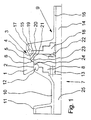
- Fig. 1 shows a housing part 1, in which a first, cylindrical valve seat 2 and a second valve seat 3 is molded.
- the second valve seat has one first conical and a cylindrical Section 4 or 5.
- On the cylindrical Section closes towards the first Valve seat a second, also conical Section 6. This section follows further on the first cylindrical valve seat 2.
- first valve seat 2 In the first valve seat 2 is a slide piston 7 trained first closing member added.
- the Sliding piston 7 is composed of a first Part 8, which faces the second closing member 9 and a second part 10, which is in one Compensating piston 11 continues. First and second Some have a recess on their circumference on, which together receive a seal 12, which on first valve seat 2 is present. First and second part are by a screw connection (not shown) connected. After removing the striker first and second part, 8 and 10 slightly apart be solved to replace the seal 12.
- the cylindrical portion 24 of the first part 8 of the Sliding piston 7 has a slightly lower one Diameter on than the first valve seat 2. Between Valve seat 2 and section 24 is therefore a gap formed with a width of typically 0.15 mm.
- the surface of the second closing member facing first part 8 is inclined towards an opening 13, which leads the leakage to a drain line 25.
- the movement of the first closing member takes place via a first valve rod 14.
- the second closing member is also in two parts built up. It consists of a third part 15, the in a second designed as a hollow rod Valve rod 16 runs out. In the second valve rod 16, the first valve rod 14 is displaceable stored. The third part has towards its edge 15 a recess together with a recess on the fourth part 18 receives a seal 17.
- the fourth part 18, the third part 15th is detachably connected by means of a screw connection, has a seal 17 along its circumference subsequent first conical section 19 on the with the corresponding first conical section 4 of the housing part 1 corresponds.
- a cylindrical section 20 which with the corresponding cylindrical section 5 of the Housing part corresponds.
- the diameter of the two cylindrical sections 5 and 20 is so chosen that between them a gap with a width of typically 0.15 mm is formed.
- To the cylindrical section 20 closes a second conical section 21, which with the corresponding second conical section 21 in Housing part 1 corresponds.
- the second closing member 9 On its side facing the spool 7 the second closing member 9 has a recess 22 on whose cylindrical inner wall 23 with the first Valve seat is aligned. It is so in its dimensions dimensioned that in it the slide piston 7 with one end can be included.
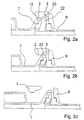
- the double seat valve forms a double seal
- the sliding piston 7 in first valve seat 2 and the second closing member 9 in second valve seat 3 is added.
- the valve closes in reverse order.
- the second Closing member 9 is through the conical section 4 guided and centered.
- With increasing training of the throttle gap the pressure of the the other side of current flowing up to medium the second locking member fully in its seat is retracted and a first seal between the lines connected to the valve.
- the Slide piston 7 releases from further lowering second locking member 9 and runs under training a second seal in the first valve seat 2 on. It is thereby from the conical section 6 guided and centered.
- the locking links are used for cleaning the seats moved individually from their rest position.
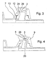
- FIGS. 5 to 7 show FIGS. 1 to 4 analog operating states of a second Embodiment of the double seat valve.
- the second valve seat includes a cylindrical Section 5 and one towards the first Valve seat 2 adjoining conical section 6.
- the second closing element is largely analogous to second closing member 9 of the first embodiment (Fig. 1) built.
- the seal 17 is the most Provided recess 22 surrounding edge and lies in the closed position of the valve in the direction to the first valve seat tapered surface 6 of the valve seat.
- the opening or closing movement of the valve takes place analogously to the first embodiment.
- the first Closing member 7 is raised and moves into the Recess 22 of the second closing member (Fig. 5b). In its further movement it lifts the first Closing member from its valve seat, with between the cylindrical surfaces 5 and 20 opened a gap becomes. Then both locking elements are in the Open position of the valve transferred (Fig. 5c).
- the valve closes in reverse Sequence of steps.
- the cleaning stroke for the first closing member 7 corresponds to that for the first Embodiment (Fig. 3) described.
- the third shown in FIGS. 8 to 10 Embodiment of the double seat valve is the Seal 17 on the cylindrical surface 20 of the second closing member 9 arranged.
- the Opening movement moves, as with the first Described embodiment, the first closing member 7th into the recess 22 of the second closing member 9 (Fig. 8b).
- both strikers 7, 9 further raised until the seal 17 from the Surface 5 slides out and between the cylindrical surfaces 5 and 20 of the valve seat 3 or the second closing member 9 provided gap releases.
- both locking members 7, 9 further transferred to the open position (Fig. 8c). With the closing movement forms accordingly first the gap between the surfaces 5 and 22, before the seal 17 moves into the valve seat.
- the cleaning stroke of the first shown in FIG. 9 Closing element corresponds to that of the first Embodiment (Fig. 3) described.
Landscapes
- Engineering & Computer Science (AREA)
- General Engineering & Computer Science (AREA)
- Mechanical Engineering (AREA)
- Lift Valve (AREA)
Claims (6)
- Vanne à double siège à commutation sans fuite comprenant :caractérisée en ce queune partie de boítier de vanne (1) avec au moins deux ouvertures pour deux conduites d'entrée et de sortie de fluide, deux sièges de soupape (2, 3) coaxiaux, prévus entre ces ouvertures, deux organes d'obturation de soupape (7, 9) qui sont guidés dans le boítier de soupape (1) pour se déplacer coaxialement l'un par rapport à l'autre et par rapport au siège de soupape (2, 3) correspondant, entre une position d'ouverture et une position de fermeture, en réalisant, en position de fermeture, un double joint d'étanchéité entre les ouvertures,le premier organe d'obturation étant un piston coulissant (7) avec des moyens d'étanchéité (12) radiaux, prévus au niveau de son segment d'extrémité, de sorte que pendant son mouvement d'ouverture, ces moyens d'étanchéité s'appliquent contre le second organe de fermeture (9) et ce dernier, au cours de la poursuite du mouvement d'ouverture, vient également dans sa position d'ouverture, alors quele premier siège de soupape (2) est cylindrique et en position de fermeture reçoit de manière étanche le piston coulissant (7), et à la fois en position de fermeture et en position d'ouverture il se forme une chambre de fuite entre les organes d'obturation, cette chambre étant reliée en permanence au côté extérieur de la vanne par une sortie (25), et que le second organe d'obturation (9) à son extrémité tournée vers le piston coulissant, a une cavité (22) à paroi périphérique essentiellement cylindrique, alignée sur le siège de soupape cylindrique (2), et dimensionnée pour recevoir, pendant le mouvement d'ouverture, le segment d'extrémité et le moyen d'étanchéité radial (12) du piston coulissant (7), de façon étanche, avant que le second organe d'obturation (9) s'ouvre,
le second siège de soupape (3) comporte une surface intérieure cylindrique (5) et le second organe d'obturation (9) comporte un segment (20) cylindrique correspondant dont le diamètre est légèrement inférieur à celui de la surface intérieure cylindrique (5) du second siège de soupape (3) et les surfaces cylindres (5, 20) forment entre elles un intervalle d'étranglement (26) lors de la course de nettoyage ainsi que lors du mouvement de fermeture et d'ouverture du second organe d'obturation (9), et
le second organe d'obturation (9) comporte un moyen d'étanchéité (17) de façon que lors du mouvement de fermeture il se forme tout d'abord l'intervalle d'étranglement (26) avant que le moyen d'étanchéité (19) ferme de manière étanche l'espace de fuite par rapport à la conduite,
le second siège de soupape (3) a au moins un segment conique (4, 6) qui fait suite à la surface intérieure cylindrique (5) et l'un des segments correspondants (19, 20) du second organe d'obturation (9) comporte le moyen d'étanchéité,
et le piston coulissant (7) présente une position de nettoyage prévue sur un côté de la position de fermeture à l'opposé du mouvement d'ouverture de sorte que dans la position de nettoyage du piston coulissant (7), un intervalle d'étranglement cylindrique (26) se forme entre la surface cylindrique (24) du piston coulissant (7) et le premier siège de soupape (2). - Vanne à double siège selon la revendication 1,
caractérisée en ce que
le moyen d'étanchéité (17) est réalisé sur le second organe d'obturation (9) également comme joint radial. - Vanne à double siège selon la revendication 1 ou 2,
caractérisée en ce que
le moyen d'étanchéité (17) est réalisé comme joint axial ou conique sur l'extrémité du second organe d'obturation tourné vers le piston coulissant (7). - Vanne à double siège selon la revendication 1, 2 ou 3,
caractérisée en ce que
le segment conique (6) du second siège de soupape (3) s'étend à partir du segment cylindrique (5) du second siège de soupape (3) vers le premier siège de soupape (2). - Vanne à double siège selon l'une des revendications 1, 2, 3, ou 4,
caractérisée en ce que
le segment conique (4) du second siège de soupape fait suite au segment cylindrique (5) du côté d'ouverture du second organe d'obturation. - Vanne à double siège selon l'une des revendications 1, 2, 3, 4, ou 5,
caractérisée en ce que
l'organe d'obturation (7, 9) se compose de deux pièces (8, 10 ; 15, 18) amovibles, de préférence reliées par une liaison vissée, et le moyen d'étanchéité (12, 17) est prévu entre les deux pièces.
Applications Claiming Priority (3)
| Application Number | Priority Date | Filing Date | Title |
|---|---|---|---|
| DE19722615 | 1997-05-30 | ||
| DE19722615A DE19722615A1 (de) | 1997-05-30 | 1997-05-30 | Leckagefrei schaltendes Doppelsitzventil |
| PCT/EP1998/002910 WO1998054494A1 (fr) | 1997-05-30 | 1998-05-18 | Soupape a double siege de commutation sans fuites |
Publications (2)
| Publication Number | Publication Date |
|---|---|
| EP0983455A1 EP0983455A1 (fr) | 2000-03-08 |
| EP0983455B1 true EP0983455B1 (fr) | 2003-04-23 |
Family
ID=7830905
Family Applications (1)
| Application Number | Title | Priority Date | Filing Date |
|---|---|---|---|
| EP98928288A Expired - Lifetime EP0983455B1 (fr) | 1997-05-30 | 1998-05-18 | Soupape a double siege de commutation sans fuites |
Country Status (6)
| Country | Link |
|---|---|
| US (1) | US6349742B1 (fr) |
| EP (1) | EP0983455B1 (fr) |
| JP (1) | JP4191256B2 (fr) |
| DE (2) | DE19722615A1 (fr) |
| DK (1) | DK0983455T3 (fr) |
| WO (1) | WO1998054494A1 (fr) |
Families Citing this family (13)
| Publication number | Priority date | Publication date | Assignee | Title |
|---|---|---|---|---|
| JP5147706B2 (ja) | 2005-11-12 | 2013-02-20 | ツーヘンハーゲン・ゲーエムベーハー | ダブルシートバルブ |
| US7543604B2 (en) * | 2006-09-11 | 2009-06-09 | Honeywell International Inc. | Control valve |
| DE202007018735U1 (de) | 2007-06-16 | 2009-03-12 | Gea Tuchenhagen Gmbh | Doppelsitzventil |
| DE102007038124B4 (de) | 2007-08-03 | 2016-01-21 | Südmo Holding GmbH | Doppelsitzventil zur Trennung von Medien |
| JP5122242B2 (ja) * | 2007-10-31 | 2013-01-16 | 岩井機械工業株式会社 | 二重弁栓装置 |
| DE102008051819A1 (de) | 2008-07-31 | 2010-02-25 | Gea Tuchenhagen Gmbh | Vorrichtung zur Verrohrung von Prozessanlagen der Nahrungsmittel- und Getränkeindustrie und Verfahren zum Betrieb einer Vorrichtung |
| DE102008026149A1 (de) * | 2008-05-30 | 2009-12-03 | Gea Tuchenhagen Gmbh | Verrohrungssystem für Prozessanlagen der Nahrungsmittel- und Getränkeindustrie |
| PT2281132E (pt) | 2008-05-30 | 2012-06-04 | Gea Tuchenhagen Gmbh | Dispositivo para a montagem de tubagens em instalações de processamento da indústria alimentar e de bebidas |
| US8327881B2 (en) * | 2008-09-19 | 2012-12-11 | Spx Corporation | Double seat valve apparatus |
| DE102011077717B4 (de) | 2011-06-17 | 2015-05-21 | Neumo Gmbh + Co. Kg | Doppelsitzventil-Vorrichtung mit Festkörperkontakt |
| DE102012003892A1 (de) | 2012-02-28 | 2013-08-29 | Gea Tuchenhagen Gmbh | Verfahren zur Reinigung eines Ventils |
| EP2861898B1 (fr) * | 2012-06-16 | 2017-02-22 | GEA Tuchenhagen GmbH | Soupape à double siège permettant un nettoyage des sièges |
| EP2868970B1 (fr) | 2013-10-29 | 2020-04-22 | Honeywell Technologies Sarl | Dispositif de régulation |
Family Cites Families (7)
| Publication number | Priority date | Publication date | Assignee | Title |
|---|---|---|---|---|
| SE424357B (sv) * | 1979-11-20 | 1982-07-12 | Hakan Jeppsson | Ventil med dubbla avtetningar |
| SE432982B (sv) * | 1980-04-24 | 1984-04-30 | Alfa Laval Ab | Blandningsseker ventil |
| ATE29568T1 (de) * | 1984-09-12 | 1987-09-15 | Lavrids Knudsen Maskinfab As | Doppelsitzventil. |
| US4605035A (en) * | 1984-09-14 | 1986-08-12 | Lavrids Knudsen Maskinefabrik A/S | Double seat valve |
| DE3835944C2 (de) * | 1988-10-21 | 1997-04-24 | Suedmo Schleicher Ag | Absperrventil mit Leckagesicherung |
| ES2091531T3 (es) * | 1993-09-21 | 1996-11-01 | Apv Rosista Gmbh | Disposicion de valvula doble que conmuta sin derrames. |
| JP4272710B2 (ja) * | 1997-03-18 | 2009-06-03 | トゥヘンハーゲン ゲーエムベーハー | 弁座洗浄可能な複座弁 |
-
1997
- 1997-05-30 DE DE19722615A patent/DE19722615A1/de not_active Withdrawn
-
1998
- 1998-05-18 DK DK98928288T patent/DK0983455T3/da active
- 1998-05-18 EP EP98928288A patent/EP0983455B1/fr not_active Expired - Lifetime
- 1998-05-18 JP JP53703498A patent/JP4191256B2/ja not_active Expired - Fee Related
- 1998-05-18 WO PCT/EP1998/002910 patent/WO1998054494A1/fr not_active Ceased
- 1998-05-18 US US09/423,988 patent/US6349742B1/en not_active Expired - Lifetime
- 1998-05-18 DE DE59808076T patent/DE59808076D1/de not_active Expired - Lifetime
Also Published As
| Publication number | Publication date |
|---|---|
| DE59808076D1 (de) | 2003-05-28 |
| DE19722615A1 (de) | 1998-12-03 |
| WO1998054494A1 (fr) | 1998-12-03 |
| EP0983455A1 (fr) | 2000-03-08 |
| JP4191256B2 (ja) | 2008-12-03 |
| US6349742B1 (en) | 2002-02-26 |
| DK0983455T3 (da) | 2003-07-28 |
| JP2001527624A (ja) | 2001-12-25 |
Similar Documents
| Publication | Publication Date | Title |
|---|---|---|
| EP0279177B1 (fr) | Vanne à volume de fuite | |
| DE2622041C2 (de) | Umschaltventil | |
| DE19548860C1 (de) | Absperrventil | |
| EP0983455B1 (fr) | Soupape a double siege de commutation sans fuites | |
| EP0968382B1 (fr) | Soupape a double siege nettoyable | |
| EP2252813B1 (fr) | Soupape à double siège, permettant le nettoyage des sièges, avec un dispositif de nettoyage pour une traversée du boîtier | |
| DE3224852A1 (de) | Doppelsitzventil | |
| DE2909972A1 (de) | Ventil mit quer beweglichem verschlusskoerper | |
| DE29713238U1 (de) | Wasserleitungsarmatur | |
| EP2232111B1 (fr) | Dispositif d'entrainement d'une soupape a double siege presentant une fonction de nettoyage du siege | |
| EP2203667B1 (fr) | Soupape a double siege avec possibilite de nettoyage de siege et procede de nettoyage de cette soupape | |
| EP0447675B1 (fr) | Ressort à gaz à longueur réglable | |
| EP0112977A1 (fr) | Organe d'arrêt pour fluides agressifs | |
| DE3607975C2 (de) | Buchsenteil einer Rohr- oder Schlauchleitungskupplung | |
| WO1995008730A1 (fr) | Procede de commutation sans fuites d'une soupape a double siege et garniture d'etancheite utile pour mettre en ×uvre ce procede | |
| EP0857901B1 (fr) | Soupape | |
| DE2900601A1 (de) | Absperrorgan | |
| DE3003480C2 (fr) | ||
| DE3502588A1 (de) | Umschaltventil | |
| DE2136857A1 (de) | Drehschieber-Ventil für Leitungen strömender Medien und Dichtung dafür | |
| DE8524858U1 (de) | Doppeltellerventil | |
| DE3610693C2 (fr) | ||
| CH660219A5 (de) | Einhebelmischventil. | |
| DE3515761C2 (fr) | ||
| DE3626628C2 (fr) |
Legal Events
| Date | Code | Title | Description |
|---|---|---|---|
| PUAI | Public reference made under article 153(3) epc to a published international application that has entered the european phase |
Free format text: ORIGINAL CODE: 0009012 |
|
| 17P | Request for examination filed |
Effective date: 19991111 |
|
| AK | Designated contracting states |
Kind code of ref document: A1 Designated state(s): DE DK FR GB IT SE |
|
| 17Q | First examination report despatched |
Effective date: 20010515 |
|
| GRAH | Despatch of communication of intention to grant a patent |
Free format text: ORIGINAL CODE: EPIDOS IGRA |
|
| GRAH | Despatch of communication of intention to grant a patent |
Free format text: ORIGINAL CODE: EPIDOS IGRA |
|
| GRAA | (expected) grant |
Free format text: ORIGINAL CODE: 0009210 |
|
| AK | Designated contracting states |
Designated state(s): DE DK FR GB IT SE |
|
| REG | Reference to a national code |
Ref country code: GB Ref legal event code: FG4D Free format text: NOT ENGLISH |
|
| REF | Corresponds to: |
Ref document number: 59808076 Country of ref document: DE Date of ref document: 20030528 Kind code of ref document: P |
|
| REG | Reference to a national code |
Ref country code: SE Ref legal event code: TRGR |
|
| REG | Reference to a national code |
Ref country code: DK Ref legal event code: T3 |
|
| GBT | Gb: translation of ep patent filed (gb section 77(6)(a)/1977) |
Effective date: 20030804 |
|
| ET | Fr: translation filed | ||
| PLBI | Opposition filed |
Free format text: ORIGINAL CODE: 0009260 |
|
| PLAX | Notice of opposition and request to file observation + time limit sent |
Free format text: ORIGINAL CODE: EPIDOSNOBS2 |
|
| 26 | Opposition filed |
Opponent name: TUCHENHAGEN GMBH Effective date: 20040121 |
|
| PLBB | Reply of patent proprietor to notice(s) of opposition received |
Free format text: ORIGINAL CODE: EPIDOSNOBS3 |
|
| PLCK | Communication despatched that opposition was rejected |
Free format text: ORIGINAL CODE: EPIDOSNREJ1 |
|
| PLBN | Opposition rejected |
Free format text: ORIGINAL CODE: 0009273 |
|
| STAA | Information on the status of an ep patent application or granted ep patent |
Free format text: STATUS: OPPOSITION REJECTED |
|
| 27O | Opposition rejected |
Effective date: 20050402 |
|
| PGFP | Annual fee paid to national office [announced via postgrant information from national office to epo] |
Ref country code: GB Payment date: 20100329 Year of fee payment: 13 |
|
| PGFP | Annual fee paid to national office [announced via postgrant information from national office to epo] |
Ref country code: FR Payment date: 20100525 Year of fee payment: 13 Ref country code: DK Payment date: 20100512 Year of fee payment: 13 |
|
| PGFP | Annual fee paid to national office [announced via postgrant information from national office to epo] |
Ref country code: IT Payment date: 20100522 Year of fee payment: 13 |
|
| PGFP | Annual fee paid to national office [announced via postgrant information from national office to epo] |
Ref country code: SE Payment date: 20100510 Year of fee payment: 13 |
|
| REG | Reference to a national code |
Ref country code: DK Ref legal event code: EBP |
|
| REG | Reference to a national code |
Ref country code: SE Ref legal event code: EUG |
|
| GBPC | Gb: european patent ceased through non-payment of renewal fee |
Effective date: 20110518 |
|
| REG | Reference to a national code |
Ref country code: FR Ref legal event code: ST Effective date: 20120131 |
|
| PG25 | Lapsed in a contracting state [announced via postgrant information from national office to epo] |
Ref country code: IT Free format text: LAPSE BECAUSE OF NON-PAYMENT OF DUE FEES Effective date: 20110518 |
|
| PG25 | Lapsed in a contracting state [announced via postgrant information from national office to epo] |
Ref country code: FR Free format text: LAPSE BECAUSE OF NON-PAYMENT OF DUE FEES Effective date: 20110531 |
|
| PG25 | Lapsed in a contracting state [announced via postgrant information from national office to epo] |
Ref country code: DK Free format text: LAPSE BECAUSE OF NON-PAYMENT OF DUE FEES Effective date: 20110531 Ref country code: GB Free format text: LAPSE BECAUSE OF NON-PAYMENT OF DUE FEES Effective date: 20110518 |
|
| PG25 | Lapsed in a contracting state [announced via postgrant information from national office to epo] |
Ref country code: SE Free format text: LAPSE BECAUSE OF NON-PAYMENT OF DUE FEES Effective date: 20110519 |
|
| PGFP | Annual fee paid to national office [announced via postgrant information from national office to epo] |
Ref country code: DE Payment date: 20170509 Year of fee payment: 20 |
|
| REG | Reference to a national code |
Ref country code: DE Ref legal event code: R071 Ref document number: 59808076 Country of ref document: DE |