EP0983460B1 - Abdeckung für druckentlastungsgerät - Google Patents
Abdeckung für druckentlastungsgerät Download PDFInfo
- Publication number
- EP0983460B1 EP0983460B1 EP98926043A EP98926043A EP0983460B1 EP 0983460 B1 EP0983460 B1 EP 0983460B1 EP 98926043 A EP98926043 A EP 98926043A EP 98926043 A EP98926043 A EP 98926043A EP 0983460 B1 EP0983460 B1 EP 0983460B1
- Authority
- EP
- European Patent Office
- Prior art keywords
- shield
- prd
- pressure relief
- cover
- relief device
- Prior art date
- Legal status (The legal status is an assumption and is not a legal conclusion. Google has not performed a legal analysis and makes no representation as to the accuracy of the status listed.)
- Expired - Lifetime
Links
- 239000012530 fluid Substances 0.000 claims abstract description 16
- 238000007789 sealing Methods 0.000 claims description 16
- 230000002093 peripheral effect Effects 0.000 claims description 10
- 230000008878 coupling Effects 0.000 claims description 4
- 238000010168 coupling process Methods 0.000 claims description 4
- 238000005859 coupling reaction Methods 0.000 claims description 4
- 230000001419 dependent effect Effects 0.000 claims description 2
- 238000009434 installation Methods 0.000 description 16
- 230000001681 protective effect Effects 0.000 description 11
- 229910052751 metal Inorganic materials 0.000 description 4
- 239000002184 metal Substances 0.000 description 4
- 239000007921 spray Substances 0.000 description 3
- 230000000007 visual effect Effects 0.000 description 3
- 238000005266 casting Methods 0.000 description 2
- 210000004907 gland Anatomy 0.000 description 2
- 239000000463 material Substances 0.000 description 2
- 238000012986 modification Methods 0.000 description 2
- 230000004048 modification Effects 0.000 description 2
- 229920000459 Nitrile rubber Polymers 0.000 description 1
- 229910000831 Steel Inorganic materials 0.000 description 1
- 230000004913 activation Effects 0.000 description 1
- 229910052782 aluminium Inorganic materials 0.000 description 1
- XAGFODPZIPBFFR-UHFFFAOYSA-N aluminium Chemical compound [Al] XAGFODPZIPBFFR-UHFFFAOYSA-N 0.000 description 1
- 230000006835 compression Effects 0.000 description 1
- 238000007906 compression Methods 0.000 description 1
- 231100001261 hazardous Toxicity 0.000 description 1
- 150000002739 metals Chemical class 0.000 description 1
- 229920003023 plastic Polymers 0.000 description 1
- 239000004033 plastic Substances 0.000 description 1
- 229920001084 poly(chloroprene) Polymers 0.000 description 1
- 230000000717 retained effect Effects 0.000 description 1
- 238000009420 retrofitting Methods 0.000 description 1
- 230000011664 signaling Effects 0.000 description 1
- 239000010959 steel Substances 0.000 description 1
Images


Classifications
-
- F—MECHANICAL ENGINEERING; LIGHTING; HEATING; WEAPONS; BLASTING
- F16—ENGINEERING ELEMENTS AND UNITS; GENERAL MEASURES FOR PRODUCING AND MAINTAINING EFFECTIVE FUNCTIONING OF MACHINES OR INSTALLATIONS; THERMAL INSULATION IN GENERAL
- F16K—VALVES; TAPS; COCKS; ACTUATING-FLOATS; DEVICES FOR VENTING OR AERATING
- F16K35/00—Means to prevent accidental or unauthorised actuation
- F16K35/10—Means to prevent accidental or unauthorised actuation with locking caps or locking bars
-
- F—MECHANICAL ENGINEERING; LIGHTING; HEATING; WEAPONS; BLASTING
- F16—ENGINEERING ELEMENTS AND UNITS; GENERAL MEASURES FOR PRODUCING AND MAINTAINING EFFECTIVE FUNCTIONING OF MACHINES OR INSTALLATIONS; THERMAL INSULATION IN GENERAL
- F16K—VALVES; TAPS; COCKS; ACTUATING-FLOATS; DEVICES FOR VENTING OR AERATING
- F16K17/00—Safety valves; Equalising valves, e.g. pressure relief valves
- F16K17/02—Safety valves; Equalising valves, e.g. pressure relief valves opening on surplus pressure on one side; closing on insufficient pressure on one side
-
- Y—GENERAL TAGGING OF NEW TECHNOLOGICAL DEVELOPMENTS; GENERAL TAGGING OF CROSS-SECTIONAL TECHNOLOGIES SPANNING OVER SEVERAL SECTIONS OF THE IPC; TECHNICAL SUBJECTS COVERED BY FORMER USPC CROSS-REFERENCE ART COLLECTIONS [XRACs] AND DIGESTS
- Y10—TECHNICAL SUBJECTS COVERED BY FORMER USPC
- Y10T—TECHNICAL SUBJECTS COVERED BY FORMER US CLASSIFICATION
- Y10T137/00—Fluid handling
- Y10T137/598—With repair, tapping, assembly, or disassembly means
- Y10T137/599—Pressure regulating type valve
-
- Y—GENERAL TAGGING OF NEW TECHNOLOGICAL DEVELOPMENTS; GENERAL TAGGING OF CROSS-SECTIONAL TECHNOLOGIES SPANNING OVER SEVERAL SECTIONS OF THE IPC; TECHNICAL SUBJECTS COVERED BY FORMER USPC CROSS-REFERENCE ART COLLECTIONS [XRACs] AND DIGESTS
- Y10—TECHNICAL SUBJECTS COVERED BY FORMER USPC
- Y10T—TECHNICAL SUBJECTS COVERED BY FORMER US CLASSIFICATION
- Y10T137/00—Fluid handling
- Y10T137/6851—With casing, support, protector or static constructional installations
- Y10T137/7043—Guards and shields
- Y10T137/7062—Valve guards
-
- Y—GENERAL TAGGING OF NEW TECHNOLOGICAL DEVELOPMENTS; GENERAL TAGGING OF CROSS-SECTIONAL TECHNOLOGIES SPANNING OVER SEVERAL SECTIONS OF THE IPC; TECHNICAL SUBJECTS COVERED BY FORMER USPC CROSS-REFERENCE ART COLLECTIONS [XRACs] AND DIGESTS
- Y10—TECHNICAL SUBJECTS COVERED BY FORMER USPC
- Y10T—TECHNICAL SUBJECTS COVERED BY FORMER US CLASSIFICATION
- Y10T137/00—Fluid handling
- Y10T137/8158—With indicator, register, recorder, alarm or inspection means
- Y10T137/8326—Fluid pressure responsive indicator, recorder or alarm
Definitions
- This invention relates to a shield for a pressure relief device for containing and deflecting released fluids and in particular to a shield which engages a relief duct while permitting the shield to be positioned in a necessary orientation on the device.
- Pressure relief devices for allowing pressurized dielectric fluid to escape from a transformer housing if the pressure in the housing increases, due either to an increase in ambient temperature or a fault in the transformer, have been known for many years.
- Known pressure relief devices of a particularly desirable type are designed so that once the release pressure is reached, a considerable amount of fluids, such as hot oil and gas, are released by the pressure release device in a very short time to rapidly reduce the pressure in the transformer housing, and prevent the housing from rupturing.
- Pressure relief devices even devices of the same type are fitted to transformer housings in a variety of arrangements. More specifically, pressure relief devices are commonly provided with switches for sensing when the devices have been actuated and remotely signaling an operator, so that the cause for the excess pressure can be investigated.
- the position of such a switch on a pressure relief device may be different from one installation to another with respect to the possible orientation of a duct for receiving released fluid, and therefore a shield must have the capability of being oriented with respect to the pressure relief device and the switch in an orientation that permits coupling to the ducting, no matter how the pressure release device itself is oriented.
- Pressure relief devices are typically fastened to transformer housings with a plurality of bolts or screws arranged in a circle. Where, as is common, six bolts are used, six different orientations of the switch, 60° apart can be achieved. However, sometimes this is not precise enough to obtain the desired orientation of a shield with respect to the device, and a position between the positions available by selection of a mounting position on the circle must be utilized.
- a shield for a pressure relief device including a peripheral wall for surrounding the pressure relief device having an edge for sealably engaging a mounting surface; a generally flat upper surface connected to the peripheral wall, the peripheral wall having a generally flat wall portion having a port therein for coupling expelled fluids to a relief duct; and a seal for sealing the edge to the mounting surface.
- the shield may have a plurality of holes in the upper surface adapted for alignment with an existing plurality of fastening holes of the pressure relief device.
- the shield may further comprise a fastener mounted to each one of the plurality of holes for attaching the upper surface to an existing one of the plurality of fastening holes of the pressure relief device and fixedly securing the shield to the pressure relief device.
- Pressure relief devices for transformers, such as QualiTROL models 208 and 213 available from QualiTROL Corporation, Fairport, N.Y., are typically attached to a transformer housing or tank by means of a flange and several bolts or screws.
- a cover encloses a release valve of the PRD and is fastened firmly to the flange by a number of screws. The release valve is held closed under normal working pressures by a compressed spring which is held in place by the cover.
- the following descriptions are for shields designed to be used with QualiTrol PRD devices but it will be readily apparent to those with ordinary skill in this field that such shields can be adapted for use with other makes and models of PRD's and such modifications are therefore contemplated by the invention.
- FIG. 1 and 2 there is shown a preferred PRD cover 20 with a ring of six symmetrically placed holes 22.
- the cover is normally mounted with six screws 24, one screw in each hole 22, which connect the cover to six male/female standoffs 26.
- the standoffs 26 are in turn screwed into six fastening holes 27 in a flange 28 of the PRD.
- An indicator 30 is located in the center of the cover 20.
- a PRD valve under the cover opens and the fluids escape between the cover and the flange and spray in all directions. Opening of the relief valve also causes the indicator 30 to rise and serve as a visual warning that the pressure has been exceeded. With such a PRD the escaping fluids are not contained and present a hazardous condition to equipment and personnel in the area. Such fluid emissions add to the time and cost of clean-up and resetting of the equipment.
- a shield for the PRD should be capable of being oriented in different positions to accommodate any limitations on placement of the ducts in different work locations. Such an enclosure should also provide access to any sensing switches on the PRD which need to be reset.
- the PRD to be shielded can be either a new installation or an existing installation.
- the PRD cover 20 also includes a resettable sensing switch 34 of the PRD which is tripped when the relief valve is actuated.
- the shield 32 includes an enclosure 36 having a peripheral wall 37 which surrounds the PRD and a port 38 in the enclosure 36 for attaching to a relief duct 40.
- the enclosure 36 is large enough to fit over the cover 20 and the switch 34 and seal with a tank to which the PRD is attached.
- the shape of the enclosure 36 can be any suitable shape, for example rectangular, semi-circular, circular or curvilinear, which can accommodate the shapes of the relief duct 40, the PRD cover 20 and any other features, for example the switch 34.
- the wall 37 is generally U-shaped having a semi-cylindrical wall portion 41 integrally connected with a rectangular-shaped flat side 42 by transitional wall portions 43.
- the flat side 42 has a rectangular-shaped port 38 for fitting to a rectangular-shaped duct 40.
- the enclosure 36 includes a sealing gasket 44 around a bottom edge for sealing with the tank.
- the upper surface 45 of the shield 32 is also provided with a removable circular cover 46 with a flange 47 for closing a circular-shaped second port 48 of the enclosure 36.
- the flange 47 is sealed to the port 48 with a second gasket 50.
- a tubular-shaped indicator 52 is mounted in an opening 54 of the cover 46 so that it is aligned with the PRD indicator 30 and will respond to actuation of indicator 30.
- the PRD cover 20 is connected to fastening holes 27 in a flange 28 of the PRD with several screws.
- the PRD cover 20 is attached to the flange with six screws 24 symmetrically arranged at 60° intervals around the cover 20 and at a fixed radius from the center of the cover. This arrangement distributes the compression force of the cover evenly around the cover and holds the spring down and the release valve closed.
- three alternating screws 24 are removed from the PRD cover 20, preferably one at a time, and replaced with three fasteners such as studs 56.
- both ends of the studs 56 are provided with male threads.
- One end of each stud 56 is screwed into the male/female standoff 26 below the existing hole 22 in the PRD cover 20.
- the standoff 26 is screwed to the flange 28 below.
- the enclosure cover 46 is provided with three holes 58 at 120° intervals around the enclosure cover 46 and at a fixed radius from the center of the cover 46, the radius being selected so that the holes 58 are aligned with the studs 56 and the enclosure cover 46 can thus be mounted to the studs 56 with nuts 60. By tightening the studs 56 and nuts 60 the cover 46 is sealed to the enclosure 36 and the enclosure 36 is sealed against the tank.
- the enclosure cover 46 is circular and is connected directly to the studs 56 the enclosure 36 can be rotated freely and oriented in any position for connection with a relief duct 40. This feature is particularly useful for retrofitting a shield to an existing PRD installation because it allows greater latitude for locating the relief duct.
- the position of a PRD sensing switch 34 on the PRD is arbitrary and is not limited to accessibility through the duct port 38 since the enclosure cover 46 can be safely removed by unscrewing the three nuts 60 to give access to the switch 34. This allows even more freedom for orienting the shield 32.
- the enclosure 36 is optionally provided with a notch 62 in the bottom edge for leading switch wiring cable through the shield 32. In original installations of a protective shield the wiring cable is preferably led through a cable gland mounted in the shield 32.
- an additional port and removable cover in the wall of the shield is provided for access to the switch.
- the switch is mounted externally to the shield rather than to the PRD cover.
- the PRD is provided with a semaphore 64 having a base 66, an arm 68 and a retaining spring 70.
- the semaphore 64 is originally attached to the PRD cover 20 by one of the screws 24 and is actuated by the indicator 30.
- the semaphore 64 provides an enhanced visual warning that the PRD valve has been actuated. It is an additional feature of the shield 32 of the invention that an existing semaphore 64 can be removed from an existing PRD and re-attached to the enclosure cover 46 by one of the studs 56 and nuts 60. The semaphore 64 can thus be actuated by the tubular-shaped indicator 52.
- Such a shield 32 is readily retrofitted to existing PRD installations or fitted with new PRD installations.
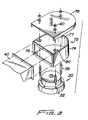
- FIG. 3 there is shown an alternative U-shaped shield 72 having an enclosure 74 with a port 76 for connecting to a duct 40 and a U-shaped port 77.
- the enclosure 74 includes a sealing gasket 75 around a bottom edge for sealing with the tank.
- the enclosure 74 has a U-shaped cover 78 which fits over the port 77 and is attached to mounting tabs 80 on the enclosure 74 with nuts 60 and studs 56.
- the studs 56 are in turn connected to the standoffs below the holes 22 in the PRD cover 20 and hence to the underlying flange.
- the shield can only be oriented in six positions at 60° increments since the enclosure 74 and cover 78 are fixedly attached to each other.
- the PRD 90 includes a cover 20, flange 28 and switch 34.
- the indicator 30 is mounted in the PRD cover 20.
- the enclosure 36 includes sealing gasket 44 and cover 46 having a flange 47 and a gasket 50 for sealing the cover 46 to the enclosure 36.
- the enclosure cover 20 is connected to alternating standoffs 26 by studs 56. Each stud 56 is screwed into a male/female standoff 26 and each standoff is in turn screwed into a fastening hole 27 in the flange 28.
- a preferred embodiment of an enclosure indicator 52 is mounted to the enclosure cover 46 by means of a bushing 94 which is fastened to the enclosure cover 46, preferably by means of a threaded screw on the end 96 of the bushing 94.
- the enclosure tubular-shaped indicator 52 includes a friction ring 98 and a flange 100.
- the base 66 of the semaphore 64 is mounted to the enclosure cover 46 by one of the studs 56 so that the tip 102 of arm 68 is positioned immediately above the enclosure indicator 52
- the bushing 94 provides the additional height necessary to have the semaphore 64 rest in a horizontal position when unactuated.
- the enclosure indicator 52 is aligned with the existing PRD indicator 30 so that on actuation of the PRD valve the existing indicator 30 impinges on the enclosure indicator 52 causing it to move up until the flange 100 contacts the end 96 of the bushing 94. Simultaneously the tip 102 is pushed up by the enclosure indicator 52 so that the arm 68 moves from a horizontal to a vertical position to visually signal the operator that the PRD valve has been actuated.
- FIG. 4 there is shown an alternative embodiment of the protective shield 32 for a PRD in which a resettable sensing switch 110 is not attached to the PRD cover 20 but is attached to the removable shield cover 46.
- an enclosure tubular-shaped indicator 112 is mounting to the enclosure cover 46 by means of a cylindrical bushing 114.
- the bushing 114 has a notch 116 cut out of the cylinder wall into which a switch arm 118 from the switch 110 is inserted when the switch 110 is mounted in the holes 120 of the shield cover 46.
- the tip of the switch arm contacts an annular groove 119 in the indicator 112.
- Activation of the enclosure indicator 112 causes it to slide up and an edge of the groove trips the switch arm 118.
- the switch can be readily checked or reset without moving the cover.
- the shield 32 is optionally provided with a notch 134 in the bottom edge for leading switch wiring cable through the shield. In original installations of a protective shield the wiring cable is preferably led through a cable gland mounted in the shield 32.
- Transformer tanks can have different surface configurations, some of which may not accommodate the mounting of a PRD directly to the surface of the tank.
- the plate would have an opening to accommodate the PRD.
- a standard protective shield mounted over the PRD would not be flush with the surface of the tank and released oil would escape through a gap between the bottom of the shield and the tank.
- an adapter plate between the welded mounting plate and the shield.
- the adapter plate surface is made wide enough to seal with the protective shield and has an opening to accommodate the PRD.
- the protective shield can be customized to seal with the tank without installing an adapter plate.
- FIG. 5 there is shown a protective shield 32, similar to that described in Figure 2, which is mounted to a PRD 90 in the same manner as described for Figure 2.
- the PRD 90 is sealed to an adapter plate 120 rather than a mounting surface of a tank 121.
- the adapter plate 120 is provided with gaskets 122, 124, mounted in grooves in the top and bottom surfaces of the plate, bolt clearance holes 126 and an opening 128 for accommodating the PRD 90.
- the adapter plate 120 is mounted to a mounting surface on the tank, such as welded plate 130, by bolts 132.
- the gasket 122 provides a seal between the PRD and the adapter plate
- the gasket 124 provides a seal between the adapter plate and the mounting surface.
- Such an adapter plate 120 can be used with all versions of the shield, such as those described for Figures 1-6.
- a limited position protective shield 150 which is field retrofittable and can be mounted to an existing PRD to direct spray in six different directions at 60° increments.
- the shield 150 is in the form of a rectangular-shaped enclosure 152 having a port 154 for connecting to a duct.
- the enclosure 152 includes a sealing gasket 153 around a bottom edge for sealing with the tank.
- the top side 156 of the enclosure 152 is attached to studs 56 which are in turn connected to the standoffs below the holes 22 in the PRD cover 20.
- a tubular-shaped indicator 52 is mounted in a bushing 94 on the top side 156.
- a semaphore 64 can be attached to the top side 156 by a nut 60 and a stud 56.
- the shield is large enough to enclose the PRD cover 20 and an alarm switch 158 attached to the PRD cover 20.
- a PRD and the shield 150 are preferably oriented so that the alarm switch 158 is positioned adjacent to the port 154 and the shield does not have to be removed to reset the switch.
- the shield 150 is provided with a sealing gasket around the bottom edge 160 of the box 152 for sealing with a transformer housing mounting surface or an adapter plate.
- the rectangular-shaped shield is readily formed from sheet metal.
- a shield of the invention can also be formed by casting, for example, by making a metal cast of the shield in one or more pieces.
- the sensing switch is usually mounted on the outside of the shield.
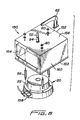
- FIG. 7 there is shown another one-piece protective shield 180, preferably formed by a casting process, for a PRD 20.
- the shield 180 has an integral mounting flange 182 surrounding the bottom edge 184 of the wall 186 and perpindicular to the wall 186.
- the flange is provided with a plurality of mounting holes and bolts 188 therein for attaching the shield to an existing tank mounting flange 190.
- a gasket 192 provides a seal between the two flanges.
- the shield 180 has a relief port 194, an external sensing switch 196 and an indicator 198. In this version of the shield there is no need to utilize the studs of the PRD to mount the shield.
- the shield 180 is especially suitable for new PRD installations and can be positioned in any desired orientation by providing several tapped holes 200 in the original mounting flange 190 of tank 204 which align with the corresponding mounting holes and bolts 188.
- the shield 210 includes an enclosure 212 and an adapter plate 214.
- the enclosure 212 has a port 216 for connecting to a duct.
- the adapter plate 214 is provide with gaskets 218, 220 mounted in grooves in the upper and lower surfaces of the plate, bolt clearance holes 222 and an opening 224 for accommodating the PRD 20.
- the adapter plate 214 is mounted to a welded plate 228 on the tank 226 by bolts 230.
- the enclosure 212 has a flat upper surface 232 integral with a peripheral wall 234 which surrounds the PRD.
- a tubular-shaped indicator 198 and an external sensing switch 196 can be mounted on the upper surface 232.
- the edge 240 of the adapter plate 214 is provided with a ledge 242 extending out from and around the bottom surface of the plate.
- a first groove 244 in and around the edge 240 holds a seal 246.
- a second groove 248 in and around the edge 240 between the ledge 242 and the first groove 244 accepts a fastening bolt 250.
- Adjacent to the bottom edge 252 of the peripheral wall there are provided a plurality of tapped mounting holes 254 for holding the bolts 250 and aligning the bolts 250 with the second groove 248.
- the enclosure 212 and the adapter plate 214 are engineered so that there is minimal clearance between the peripheral wall 234 and the edge 240.
- the seal 246 in the first groove 244 thus seals tightly with the wall 234.
- the bolts 250 are screwed through the mounting holes 254 so that they extend into the second groove 248 and hold down the enclosure 212. Since the groove 248 extends around the plate 214 the enclosure 234 can be rotated and oriented in any direction for coupling the port 216 to a duct.
- a protective shield of the invention can be formed from any suitable metal or plastic materials which are strong enough to withstand the temperatures and pressures involved and are resistant to the environment, for example, metals such as steel or aluminum.
- the sealing gaskets and friction rings are preferably made of oil resistant elastomeric materials, such as neoprene and nitrile rubbers.
- a preferred shield of the invention can be readily oriented with respect to a PRD and ductwork and can be readily retrofitted to existing PRD's. Such retrofitted shields are less expensive to install than integrally shielded pressure relief devices.
- the shield can be retrofitted without removing the PRD by using studs connected between the PRD and the enclosure cover.
- the two-piece design of the shield allows for access to an alarm switch equipped PRD's without removing the ductwork.
- a preferred shield permits use of a visual semaphore, and an existing semaphore of an unshielded PRD can be remounted on the shield.
Landscapes
- Engineering & Computer Science (AREA)
- General Engineering & Computer Science (AREA)
- Mechanical Engineering (AREA)
- Shielding Devices Or Components To Electric Or Magnetic Fields (AREA)
- Pressure Vessels And Lids Thereof (AREA)
- Preventing Unauthorised Actuation Of Valves (AREA)
- Electrical Discharge Machining, Electrochemical Machining, And Combined Machining (AREA)
- Measuring Fluid Pressure (AREA)
- Food Preservation Except Freezing, Refrigeration, And Drying (AREA)
- Paper (AREA)
- Battery Mounting, Suspending (AREA)
- Driving Mechanisms And Operating Circuits Of Arc-Extinguishing High-Tension Switches (AREA)
Claims (10)
- Abdeckung (32; 72; 150; 180; 210) für eine Druckentlastungsvorrichtung (90), umfassend:eine Außenwand (37; 74; 152; 186; 234) zum Umgeben der Druckentlastungsvorrichtung (90) mit einem Rand (160; 184; 252) zum dichtenden Angreifen einer Montagefläche (130; 190; 228) undeine allgemein flache obere Fläche (45; 46; 78; 156; 232), die mit der Außenwand (37; 74; 152; 186; 234) verbunden ist, dadurch gekennzeichnet, dass die Außenwand (37; 74; 152; 186; 234) einen allgemein flachen Wandteil (42) hat mit einer Öffnung (38; 76; 154; 194; 216) darin zum Koppeln von an einen Auslasskanal (40) ausgestoßener Fluide; undeine Dichtung (44; 75; 153; 190) zum Abdichten des Randes (160; 184; 252) der Montagefläche (130; 190; 228).
- Abdeckung nach Anspruch 1, bei welcher die obere Fläche (46; 78; 156) eine Vielzahl von Löchern (58) hat, die zur Ausrichtung mit einer vorhandenen Vielzahl von Befestigungslöchern (22) der Druckentlastungsvorrichtung (90) ausgelegt sind.
- Abdeckung nach Anspruch 1 oder 2, weiterhin umfassend eine Befestigung (24; 56), die an jedem einer Vielzahl von Löchern (58) zum Befestigen der oberen Fläche (46; 78; 156) an ein vorhandenes der Vielzahl von Befestigungslöchern (22) der Druckentlastungsvorrichtung (90) und festen Sichern der Abdeckung (32; 72; 150; 180; 210) an der Druckentlastungsvorrichtung (90) angebracht ist.
- Abdeckung nach Anspruch 1, 2 oder 3, weiterhin umfassend einen Anzeiger (52; 112; 198), der an der oberen Fläche (46; 78; 156; 232) befestigt ist und beweglich in Erwiderung der Betätigung der Druckentlastungsvorrichtung (90) ist.
- Abdeckung nach Anspruch 4, weiterhin umfassend einen Winker (64), der in Erwiderung der Betätigung des Anzeigers (52; 112; 198) beweglich ist.
- Abdeckung nach einem der Ansprüche 1 - 5, weiterhin umfassend eine Adapterplatte (120; 214) mit einer oberen Fläche zum Angreifen der Dichtung (44; 75; 153; 190), eine Öffnung (128; 224), die sich durch die Platte erstreckt, einen ersten Dichtring (122; 218), der an der oberen Fläche der Platte angebracht ist und die Öffnung zum Abdichten der Druckentlastungsvorrichtung (90) an der Platte (120; 214) umgibt und einen zweiten Dichtring (124; 220), der an eine untere Fläche der Platte angebracht ist und die Öffnung (128; 224) zum Dichten der Platte (120; 214) an der Montagefläche (130; 228) umgibt.
- Abdeckung nach einem der Ansprüche 1 - 5, weiterhin umfassend einen integralen Montageflansch (182), der senkrecht zur Wand (186) ist und den Rand (184) umgibt.
- Abdeckung nach Anspruch 7, bei welchem der Flansch (182) eine Vielzahl von Montagelöchern zum festen Anbringen der Abdeckung (180) an der Montagefläche (190) umfasst.
- Abdeckung nach Anspruch 1 und umfassend ein zweites Loch (48; 77) und eine abnehmbare Kappe (46; 78), die fest an die Druckentlastungsvorrichtung (90) befestigt werden kann, wobei die Kappe (46; 78) eine Fläche (47) zum Dichten des zweiten Loches (48; 77) hat.
- Abdeckung nach Anspruch 2 oder einem der Ansprüche 3 - 9, wenn abhängig von Anspruch 2, worin die obere Oberfläche eine abnehmbare Kappe (46; 78) umfasst, die Abdeckung weiterhin einen Bolzen (56) umfasst, der an jeder der Vielzahl von Löchern (58) angebracht ist, zum Befestigen der Kappe (46; 78) an einem vorhandenen Befestigungsloch (22) der Druckentlastungsvorrichtung (90).
Applications Claiming Priority (3)
| Application Number | Priority Date | Filing Date | Title |
|---|---|---|---|
| US08/863,155 US5937893A (en) | 1997-05-27 | 1997-05-27 | Shield for pressure relief device |
| US863155 | 1997-05-27 | ||
| PCT/US1998/010204 WO1998054498A1 (en) | 1997-05-27 | 1998-05-19 | Shield for pressure relief device |
Publications (3)
| Publication Number | Publication Date |
|---|---|
| EP0983460A1 EP0983460A1 (de) | 2000-03-08 |
| EP0983460A4 EP0983460A4 (de) | 2002-08-28 |
| EP0983460B1 true EP0983460B1 (de) | 2005-11-09 |
Family
ID=25340407
Family Applications (1)
| Application Number | Title | Priority Date | Filing Date |
|---|---|---|---|
| EP98926043A Expired - Lifetime EP0983460B1 (de) | 1997-05-27 | 1998-05-19 | Abdeckung für druckentlastungsgerät |
Country Status (8)
| Country | Link |
|---|---|
| US (1) | US5937893A (de) |
| EP (1) | EP0983460B1 (de) |
| JP (1) | JP4014649B2 (de) |
| AT (1) | ATE309495T1 (de) |
| CA (1) | CA2291084C (de) |
| DE (1) | DE69832273T2 (de) |
| ES (1) | ES2253818T3 (de) |
| WO (1) | WO1998054498A1 (de) |
Families Citing this family (10)
| Publication number | Priority date | Publication date | Assignee | Title |
|---|---|---|---|---|
| US6497248B2 (en) | 2001-01-18 | 2002-12-24 | Qualitrol Corporation | Pressure relief device with one piece gasket |
| EP1604138B1 (de) * | 2003-03-19 | 2008-03-19 | Maschinenfabrik Reinhausen GmbH | Druckentlastungsventil |
| DE10312177B3 (de) * | 2003-03-19 | 2004-06-17 | Maschinenfabrik Reinhausen Gmbh | Druckentlastungsventil |
| US7210497B2 (en) * | 2003-12-19 | 2007-05-01 | Qualitrol Corporation | Pressure relief device with increased flow rate |
| US7111637B2 (en) * | 2003-12-19 | 2006-09-26 | Qualitrol Corporation | Enclosure system for pressure relief device |
| DE102004024523B3 (de) * | 2004-05-18 | 2005-11-24 | Dr.Ing.H.C. F. Porsche Ag | Transportschutz für Kabelenden an Federbeinen |
| US20080196920A1 (en) * | 2005-07-15 | 2008-08-21 | Siemens Aktiengesellschaft | Expansion Vessel for Stepping Switches |
| US8839658B2 (en) * | 2011-03-31 | 2014-09-23 | Qualitrol Company, Llc | Combination of hydrogen and pressure sensors |
| US9594410B1 (en) * | 2013-06-07 | 2017-03-14 | Western Digital Technologies, Inc. | Method and system for removing heat from multiple controllers on a circuit board |
| US10398153B2 (en) * | 2016-06-30 | 2019-09-03 | Miguel Angel Fernandez | Liquid nitrogen dispenser for frozen treats |
Family Cites Families (4)
| Publication number | Priority date | Publication date | Assignee | Title |
|---|---|---|---|---|
| US2335829A (en) * | 1941-09-23 | 1943-11-30 | American Car & Foundry Co | Protected safety valve |
| US5058758A (en) * | 1991-01-07 | 1991-10-22 | Suddeth Bucky D | Compressed gas cylinder valve and gauge protector |
| US5529089A (en) * | 1992-10-13 | 1996-06-25 | Williams Controls, Inc. | Modular compressed natural gas fuel unit |
| US5687757A (en) * | 1995-05-04 | 1997-11-18 | Perry C. Heintz | Secure lock and spill preventer for fluid storage facility |
-
1997
- 1997-05-27 US US08/863,155 patent/US5937893A/en not_active Expired - Lifetime
-
1998
- 1998-05-19 EP EP98926043A patent/EP0983460B1/de not_active Expired - Lifetime
- 1998-05-19 JP JP50075299A patent/JP4014649B2/ja not_active Expired - Lifetime
- 1998-05-19 ES ES98926043T patent/ES2253818T3/es not_active Expired - Lifetime
- 1998-05-19 AT AT98926043T patent/ATE309495T1/de active
- 1998-05-19 WO PCT/US1998/010204 patent/WO1998054498A1/en not_active Ceased
- 1998-05-19 CA CA 2291084 patent/CA2291084C/en not_active Expired - Fee Related
- 1998-05-19 DE DE1998632273 patent/DE69832273T2/de not_active Expired - Lifetime
Also Published As
| Publication number | Publication date |
|---|---|
| WO1998054498A1 (en) | 1998-12-03 |
| ATE309495T1 (de) | 2005-11-15 |
| DE69832273T2 (de) | 2006-07-06 |
| JP4014649B2 (ja) | 2007-11-28 |
| DE69832273D1 (de) | 2005-12-15 |
| JP2002502551A (ja) | 2002-01-22 |
| ES2253818T3 (es) | 2006-06-01 |
| CA2291084C (en) | 2003-11-18 |
| EP0983460A4 (de) | 2002-08-28 |
| US5937893A (en) | 1999-08-17 |
| CA2291084A1 (en) | 1998-12-03 |
| EP0983460A1 (de) | 2000-03-08 |
Similar Documents
| Publication | Publication Date | Title |
|---|---|---|
| EP0983460B1 (de) | Abdeckung für druckentlastungsgerät | |
| US20070164247A1 (en) | Valve device | |
| JP3974582B2 (ja) | 破断可能な保護部を具備するケーブル挿入等のための構造 | |
| US7552744B2 (en) | Decompression valve | |
| US20130240771A1 (en) | Ball valve with integrated fugitive emission assembly | |
| EP1704352B1 (de) | Druckentlastungsvorrichtung mit erhöhtem durchfluss | |
| EP0514496B1 (de) | Zündanlage für maschinen mit einem transformator und dessen einstellungsmitteln | |
| EP0607708A1 (de) | Absperrschieber | |
| US5529087A (en) | System for remotely servicing a top loading captive ball valve | |
| US4168415A (en) | Pressure switch having modular construction | |
| MXPA99010914A (en) | Shield for pressure relief device | |
| GB2265427A (en) | Safety cover for valve disconnection means | |
| CN100398889C (zh) | 卸压阀 | |
| CN1247931C (zh) | 液化气容器 | |
| JP2007515793A (ja) | 圧力逃がし装置のための包囲システム | |
| JP3532758B2 (ja) | 計器用変成器 | |
| US10298229B2 (en) | Switch adapter | |
| JP2020143451A (ja) | バルブカバー、およびエア抜きバルブとバルブカバーの組み合わせ体 | |
| CN211039827U (zh) | 防爆阀 | |
| US5601109A (en) | Fluid flow monitor | |
| EP0611460B1 (de) | Gasdrucksteuergerät | |
| CN220960335U (zh) | 变压器用温控器温包防护结构及变压器 | |
| JPH09219320A (ja) | 負荷時タップ切換変圧器 | |
| CN223965705U (zh) | 膨胀阀保护盒结构及谷物冷却机组 | |
| US20240068591A1 (en) | Integrating fluid pathways into a valve superstructure |
Legal Events
| Date | Code | Title | Description |
|---|---|---|---|
| PUAI | Public reference made under article 153(3) epc to a published international application that has entered the european phase |
Free format text: ORIGINAL CODE: 0009012 |
|
| 17P | Request for examination filed |
Effective date: 19991224 |
|
| AK | Designated contracting states |
Kind code of ref document: A1 Designated state(s): AT BE CH CY DE DK ES FI FR GB GR IE IT LI LU MC NL PT SE |
|
| A4 | Supplementary search report drawn up and despatched |
Effective date: 20020717 |
|
| AK | Designated contracting states |
Kind code of ref document: A4 Designated state(s): AT BE CH CY DE DK ES FI FR GB GR IE IT LI LU MC NL PT SE |
|
| 17Q | First examination report despatched |
Effective date: 20030321 |
|
| GRAP | Despatch of communication of intention to grant a patent |
Free format text: ORIGINAL CODE: EPIDOSNIGR1 |
|
| RIC1 | Information provided on ipc code assigned before grant |
Ipc: 7F 16K 35/10 B Ipc: 7F 16K 17/02 A |
|
| GRAS | Grant fee paid |
Free format text: ORIGINAL CODE: EPIDOSNIGR3 |
|
| GRAA | (expected) grant |
Free format text: ORIGINAL CODE: 0009210 |
|
| AK | Designated contracting states |
Kind code of ref document: B1 Designated state(s): AT BE CH CY DE DK ES FI FR GB GR IE IT LI LU MC NL PT SE |
|
| PG25 | Lapsed in a contracting state [announced via postgrant information from national office to epo] |
Ref country code: NL Free format text: LAPSE BECAUSE OF FAILURE TO SUBMIT A TRANSLATION OF THE DESCRIPTION OR TO PAY THE FEE WITHIN THE PRESCRIBED TIME-LIMIT Effective date: 20051109 Ref country code: LI Free format text: LAPSE BECAUSE OF FAILURE TO SUBMIT A TRANSLATION OF THE DESCRIPTION OR TO PAY THE FEE WITHIN THE PRESCRIBED TIME-LIMIT Effective date: 20051109 Ref country code: FI Free format text: LAPSE BECAUSE OF FAILURE TO SUBMIT A TRANSLATION OF THE DESCRIPTION OR TO PAY THE FEE WITHIN THE PRESCRIBED TIME-LIMIT Effective date: 20051109 Ref country code: CH Free format text: LAPSE BECAUSE OF FAILURE TO SUBMIT A TRANSLATION OF THE DESCRIPTION OR TO PAY THE FEE WITHIN THE PRESCRIBED TIME-LIMIT Effective date: 20051109 |
|
| REG | Reference to a national code |
Ref country code: GB Ref legal event code: FG4D |
|
| REG | Reference to a national code |
Ref country code: CH Ref legal event code: EP |
|
| REG | Reference to a national code |
Ref country code: IE Ref legal event code: FG4D |
|
| REF | Corresponds to: |
Ref document number: 69832273 Country of ref document: DE Date of ref document: 20051215 Kind code of ref document: P |
|
| PG25 | Lapsed in a contracting state [announced via postgrant information from national office to epo] |
Ref country code: SE Free format text: LAPSE BECAUSE OF FAILURE TO SUBMIT A TRANSLATION OF THE DESCRIPTION OR TO PAY THE FEE WITHIN THE PRESCRIBED TIME-LIMIT Effective date: 20060209 Ref country code: GR Free format text: LAPSE BECAUSE OF FAILURE TO SUBMIT A TRANSLATION OF THE DESCRIPTION OR TO PAY THE FEE WITHIN THE PRESCRIBED TIME-LIMIT Effective date: 20060209 Ref country code: DK Free format text: LAPSE BECAUSE OF FAILURE TO SUBMIT A TRANSLATION OF THE DESCRIPTION OR TO PAY THE FEE WITHIN THE PRESCRIBED TIME-LIMIT Effective date: 20060209 |
|
| NLV1 | Nl: lapsed or annulled due to failure to fulfill the requirements of art. 29p and 29m of the patents act | ||
| PG25 | Lapsed in a contracting state [announced via postgrant information from national office to epo] |
Ref country code: IE Free format text: LAPSE BECAUSE OF NON-PAYMENT OF DUE FEES Effective date: 20060519 |
|
| PG25 | Lapsed in a contracting state [announced via postgrant information from national office to epo] |
Ref country code: MC Free format text: LAPSE BECAUSE OF NON-PAYMENT OF DUE FEES Effective date: 20060531 |
|
| REG | Reference to a national code |
Ref country code: CH Ref legal event code: PL |
|
| REG | Reference to a national code |
Ref country code: ES Ref legal event code: FG2A Ref document number: 2253818 Country of ref document: ES Kind code of ref document: T3 |
|
| PLBE | No opposition filed within time limit |
Free format text: ORIGINAL CODE: 0009261 |
|
| STAA | Information on the status of an ep patent application or granted ep patent |
Free format text: STATUS: NO OPPOSITION FILED WITHIN TIME LIMIT |
|
| 26N | No opposition filed |
Effective date: 20060810 |
|
| PG25 | Lapsed in a contracting state [announced via postgrant information from national office to epo] |
Ref country code: FR Free format text: LAPSE BECAUSE OF FAILURE TO SUBMIT A TRANSLATION OF THE DESCRIPTION OR TO PAY THE FEE WITHIN THE PRESCRIBED TIME-LIMIT Effective date: 20061020 |
|
| EN | Fr: translation not filed | ||
| REG | Reference to a national code |
Ref country code: IE Ref legal event code: MM4A |
|
| PG25 | Lapsed in a contracting state [announced via postgrant information from national office to epo] |
Ref country code: LU Free format text: LAPSE BECAUSE OF NON-PAYMENT OF DUE FEES Effective date: 20060519 |
|
| PG25 | Lapsed in a contracting state [announced via postgrant information from national office to epo] |
Ref country code: FR Free format text: LAPSE BECAUSE OF FAILURE TO SUBMIT A TRANSLATION OF THE DESCRIPTION OR TO PAY THE FEE WITHIN THE PRESCRIBED TIME-LIMIT Effective date: 20051109 Ref country code: CY Free format text: LAPSE BECAUSE OF FAILURE TO SUBMIT A TRANSLATION OF THE DESCRIPTION OR TO PAY THE FEE WITHIN THE PRESCRIBED TIME-LIMIT Effective date: 20051109 |
|
| PGFP | Annual fee paid to national office [announced via postgrant information from national office to epo] |
Ref country code: PT Payment date: 20110331 Year of fee payment: 14 Ref country code: ES Payment date: 20110520 Year of fee payment: 14 |
|
| PGFP | Annual fee paid to national office [announced via postgrant information from national office to epo] |
Ref country code: AT Payment date: 20110518 Year of fee payment: 14 Ref country code: GB Payment date: 20110518 Year of fee payment: 14 |
|
| PGFP | Annual fee paid to national office [announced via postgrant information from national office to epo] |
Ref country code: BE Payment date: 20110606 Year of fee payment: 14 |
|
| REG | Reference to a national code |
Ref country code: PT Ref legal event code: MM4A Free format text: LAPSE DUE TO NON-PAYMENT OF FEES Effective date: 20121119 |
|
| BERE | Be: lapsed |
Owner name: *QUALITROL CORP. Effective date: 20120531 |
|
| REG | Reference to a national code |
Ref country code: AT Ref legal event code: MM01 Ref document number: 309495 Country of ref document: AT Kind code of ref document: T Effective date: 20120519 |
|
| GBPC | Gb: european patent ceased through non-payment of renewal fee |
Effective date: 20120519 |
|
| PG25 | Lapsed in a contracting state [announced via postgrant information from national office to epo] |
Ref country code: AT Free format text: LAPSE BECAUSE OF NON-PAYMENT OF DUE FEES Effective date: 20120519 |
|
| PG25 | Lapsed in a contracting state [announced via postgrant information from national office to epo] |
Ref country code: PT Free format text: LAPSE BECAUSE OF NON-PAYMENT OF DUE FEES Effective date: 20121119 Ref country code: BE Free format text: LAPSE BECAUSE OF NON-PAYMENT OF DUE FEES Effective date: 20120531 |
|
| PG25 | Lapsed in a contracting state [announced via postgrant information from national office to epo] |
Ref country code: GB Free format text: LAPSE BECAUSE OF NON-PAYMENT OF DUE FEES Effective date: 20120519 |
|
| REG | Reference to a national code |
Ref country code: ES Ref legal event code: FD2A Effective date: 20130821 |
|
| PG25 | Lapsed in a contracting state [announced via postgrant information from national office to epo] |
Ref country code: ES Free format text: LAPSE BECAUSE OF NON-PAYMENT OF DUE FEES Effective date: 20120520 |
|
| PGFP | Annual fee paid to national office [announced via postgrant information from national office to epo] |
Ref country code: DE Payment date: 20170530 Year of fee payment: 20 |
|
| PGFP | Annual fee paid to national office [announced via postgrant information from national office to epo] |
Ref country code: IT Payment date: 20170524 Year of fee payment: 20 |
|
| REG | Reference to a national code |
Ref country code: DE Ref legal event code: R071 Ref document number: 69832273 Country of ref document: DE |