EP0983826A2 - Manipulateur pour positionner des sondes dans des appareils et dans des chambres - Google Patents
Manipulateur pour positionner des sondes dans des appareils et dans des chambres Download PDFInfo
- Publication number
- EP0983826A2 EP0983826A2 EP99116530A EP99116530A EP0983826A2 EP 0983826 A2 EP0983826 A2 EP 0983826A2 EP 99116530 A EP99116530 A EP 99116530A EP 99116530 A EP99116530 A EP 99116530A EP 0983826 A2 EP0983826 A2 EP 0983826A2
- Authority
- EP
- European Patent Office
- Prior art keywords
- sample
- tube
- manipulator
- rotation
- cooling device
- Prior art date
- Legal status (The legal status is an assumption and is not a legal conclusion. Google has not performed a legal analysis and makes no representation as to the accuracy of the status listed.)
- Granted
Links
Images




Classifications
-
- H—ELECTRICITY
- H01—ELECTRIC ELEMENTS
- H01J—ELECTRIC DISCHARGE TUBES OR DISCHARGE LAMPS
- H01J37/00—Discharge tubes with provision for introducing objects or material to be exposed to the discharge, e.g. for the purpose of examination or processing thereof
- H01J37/02—Details
- H01J37/20—Means for supporting or positioning the object or the material; Means for adjusting diaphragms or lenses associated with the support
-
- B—PERFORMING OPERATIONS; TRANSPORTING
- B25—HAND TOOLS; PORTABLE POWER-DRIVEN TOOLS; MANIPULATORS
- B25J—MANIPULATORS; CHAMBERS PROVIDED WITH MANIPULATION DEVICES
- B25J1/00—Manipulators positioned in space by hand
- B25J1/08—Manipulators positioned in space by hand movably mounted in a wall
- B25J1/10—Sleeve and pivot mountings therefor
Definitions
- the invention relates to a manipulator for positioning Samples in equipment and chambers, especially in Ultra high vacuum chambers.
- the manipulator is suitable for the Use in apparatus and chambers in which material samples to be examined, processed or coated.
- manipulators for setting the Sample position in vacuum chambers There are already manipulators for setting the Sample position in vacuum chambers known. With one of these It is possible to manipulate the position of one within the manipulator Chamber located sample in two directions of movement to be adjusted (catalog vacuum components from Caburn-MDC, East Wales, GB, 1997/98, p. 375).
- the vertical arranged disc-shaped sample around its vertical axis (polar rotation) and about its horizontal axis (azimuth rotation) be rotated.
- the sample is attached to a sample holder, which can be operated accordingly.
- the Sample carrier serves for azimuth rotation of the sample Gear transmission that drives a shaft from an actuator is driven.
- the shaft is in one in the Vacuum apparatus protruding guide tube that is used for realization the polar rotation of the sample with one on the apparatus existing actuator can be rotated axially.
- the invention has for its object a manipulator for Positioning of samples in apparatus and chambers, especially in ultra high vacuum chambers where facilities for azimuthal, polar and tilting rotation of the sample holder and a device for cooling the sample are available, so to design that very low sample temperatures up to below 20 K and are universal and precise Setting the sample position in the 3 spatial axes is possible.
- the rotary slide consists of a coaxial around the holding tube arranged inner tube and one around this coaxially arranged outer tube, the inner tube on Holding tube is guided axially displaceable and where that Outer tube on the inner tube can be rotated transversely to its longitudinal axis is stored.
- the rope of the cable is conveniently one over Rope pulley guided rope loop, with one of the rope pulleys on the axis of the sample carrier for performing the azimuth rotation the sample is attached.
- the ends of the rope loop are there with the interposition of a tension spring.
- a is located within the cooling device Pipe for transporting liquid coolant to the arranged lower end of the cooling device, and for the Return of the coolant are within the Cooling device arranged coaxially around one or several heat exchanger tubes available.
- the manipulator according to the invention for positioning samples in apparatus and chambers, especially in Ultra-high vacuum chambers, advantageously enables one universal and precise adjustment of the position of a sample in the 3 spatial axes.
- a particular advantage of this manipulator is that the crossing point of the three is perpendicular mutually rotating axes exactly in the sample surface lies.
- all movements are independent of one another, so that a default of one size when changing another is not necessary.
- this Manipulator a sample change under examination conditions in is possible in situ. Because all movements are generated ex situ is also computer-aided automation possible.
- intensive cooling of the Sample is possible, down to the range of below 20 K.
- Another advantage is that the Cooling device is stationary and none of the movements of the Mechanics participate. The cooling device acts directly on the Sample without cooling other assemblies. This has the Advantage that the entire mechanics remain at room temperature.
- the assembly shown in Fig. 1 for executing a Azimuth rotation of the sample essentially consists of one Rotary actuator 1 with electric servomotor 2, one Gear 3 / rack 4 pairing, a rotary slide 5, one Control rod 6 and a cable 7.
- the rotary slide 5 is rotatable and movable in the vertical direction on a holding tube 8 arranged and consists of a coaxially around the holding tube 8th arranged inner tube 9 and a coaxial around this arranged outer tube 10.
- the inner tube 9 is on the holding tube 8th guided axially displaceable.
- the outer tube 10 is on the inner tube 9 rotatably mounted transversely to its longitudinal axis.
- the cable 7 consists of a rope loop that runs over two rope pulleys 11; 12 is led.
- the ends of the rope loop are under each other Interposition of a compensation spring connected, whereby compensated for thermal effects and the necessary tension of the Rope loop is guaranteed under all operating conditions.
- the adjusting rod 6 attached to the rotary slide 5 is on her lower end by means of a clamp connection 13 on the cable 7 clamped.
- the pulley 12 sits on one for the Azimuth rotation existing horizontal axis of rotation of the Sample holder 14. On the sample holder 14 is in the vertical Position a disk-shaped sample P attached (see Fig. 3).
- This module works as follows: With a Actuation of the servomotor 2 is via the Gear 3 / rack 4-pairing of the rotary slide 5 in moved vertically on the holding tube 8. Thereby the cable 7 is actuated via the control rod 6. this leads to to rotate the pulleys 11; 12, with the lower Rope pulley 12 of the sample carrier 14 about its horizontal axis rotated and thus performed the azimuth rotation of the sample P. becomes.
- the assembly shown in Fig. 2 for executing a polar rotation of the sample P consists essentially of a Rotary actuator 15 with an electric servomotor 16, one Bevel gear pairing 17; 18, the holding tube 8 and two Holding strips 19 which hold the sample carrier 14.
- This module works as follows: With a Actuation of the servomotor 16 is via the bevel gear pairing 17; 18 the support tube 8 rotated about its axis. In order to becomes the sample holder 14 held with the holding strips 19 rotated the vertical axis and thus the polar rotation of the Sample P executed.
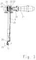
- the assembly shown in Fig. 3 for executing a Tilting the sample P consists essentially of a Rotary actuator 20 with an electric servomotor 21, one Gear 22 / rack 23 pairing, a rotary slide 24, one Adjustment rod 25 and an angular articulated lever 26.
- Der Rotary slide 24 is rotatable and in the vertical direction movably arranged on the holding tube 8 and consists of a arranged coaxially around the holding tube 8 inner tube 27 and a around this coaxially arranged outer tube 28.
- the inner tube 27 is guided axially displaceably on the holding tube 8.
- the outer tube 28 is rotatably mounted on the inner tube 27 transversely to its longitudinal axis.
- the articulated lever 26 is pivotable about the bearing point 29 and on its lower end firmly connected to the sample holder 14.
- This module works as follows: With a Actuation of the servomotor 21 is via the Gear 22 / rack 23 pairing of the rotary slide 24 in moved vertically on the holding tube 8. Thereby is about the control rod 25, the articulated lever 26 to the Bearing point 29 pivoted. This causes a tilting movement of the Sample P.
- the assembly for cooling shown in FIGS. 4a and 4b the sample P consists essentially of a tubular Cooling device 30, which is inside the holding tube 8 (in the 4a and 4b (not shown) to this non-contact is arranged, and from a highly thermally conductive flexible Metallstrang 31, the lower end of the cooling device 30 and connects the sample carrier 14 to one another in a heat-conducting manner.
- A is located within the cooling device 30 Pipe 32 for transporting liquid coolant to the lower end of the cooling device to the well thermally conductive flexible metal strand 31. This consists of copper braid.
- liquid coolant serves liquid helium He, which has a Helium supply 33 is passed into the cooling device 30.
- the Heat exchanger tube 34 is in the lower part of the conduit 30 a longitudinally porous tubular heat exchanger for Return of the coolant, which is made of sintered copper consists. Above the heat exchanger tube 34 closes further return transport of the coolant, the heat exchanger tube 35 that has a spiral on its outside Has coolant channel 36 and consists of copper. At the top The end of the heat exchanger tube 35 rises in the reflux Coolant in the space between the outer jacket the cooling device 30 and an inner tube 37 to one Helium discharge 38 and there is from the heat exchanger taken. It is therefore not part of the UHV system.
- the overall structure of the manipulator consists of the assemblies described above. This Manipulator enables simultaneous, decoupled rotation around the polar, azimuthal and a perpendicular axis Temperatures below 10 K.
Landscapes
- Engineering & Computer Science (AREA)
- Robotics (AREA)
- Mechanical Engineering (AREA)
- Chemical & Material Sciences (AREA)
- Analytical Chemistry (AREA)
- Sampling And Sample Adjustment (AREA)
- Manipulator (AREA)
- Analysing Materials By The Use Of Radiation (AREA)
Applications Claiming Priority (2)
| Application Number | Priority Date | Filing Date | Title |
|---|---|---|---|
| DE19839871 | 1998-09-02 | ||
| DE19839871A DE19839871C2 (de) | 1998-09-02 | 1998-09-02 | Manipulator zur Positionierung von Proben in Apparaturen und Kammern |
Publications (3)
| Publication Number | Publication Date |
|---|---|
| EP0983826A2 true EP0983826A2 (fr) | 2000-03-08 |
| EP0983826A3 EP0983826A3 (fr) | 2000-05-31 |
| EP0983826B1 EP0983826B1 (fr) | 2002-05-02 |
Family
ID=7879477
Family Applications (1)
| Application Number | Title | Priority Date | Filing Date |
|---|---|---|---|
| EP99116530A Expired - Lifetime EP0983826B1 (fr) | 1998-09-02 | 1999-08-24 | Manipulateur pour positionner des sondes dans des appareils et dans des chambres |
Country Status (3)
| Country | Link |
|---|---|
| EP (1) | EP0983826B1 (fr) |
| AT (1) | ATE216944T1 (fr) |
| DE (2) | DE19839871C2 (fr) |
Cited By (1)
| Publication number | Priority date | Publication date | Assignee | Title |
|---|---|---|---|---|
| WO2014053670A1 (fr) | 2012-10-02 | 2014-04-10 | Avs Added Value Industrial Engineering Solutions, S.L. | Manipulateur pour chambre à ultra-vide |
Family Cites Families (11)
| Publication number | Priority date | Publication date | Assignee | Title |
|---|---|---|---|---|
| JPS5126613Y2 (fr) * | 1971-06-19 | 1976-07-06 | ||
| DE2542360C2 (de) * | 1975-09-19 | 1977-11-17 | Siemens AG, 1000 Berlin und 8000 München | Korpuskularstrahlgerät mit einem Goniometer |
| DE3423432C2 (de) * | 1984-06-26 | 1986-06-12 | Deutsche Forschungs- und Versuchsanstalt für Luft- und Raumfahrt e.V., 5000 Köln | Vorrichtung zur Positionierung einer Probe |
| FR2644290A1 (fr) * | 1989-03-10 | 1990-09-14 | Labo Electronique Physique | Micromanipulateur |
| NL8902568A (nl) * | 1989-10-17 | 1991-05-16 | Philips Nv | Vacuuem systeem voorzien van een evacueerbaar huis, een objecthouder en een losneembaar daarmee gekoppelde objectdrager. |
| JP2984083B2 (ja) * | 1991-04-04 | 1999-11-29 | 日本電子株式会社 | 電子顕微鏡用試料駆動装置 |
| JP3168814B2 (ja) * | 1994-03-31 | 2001-05-21 | 株式会社島津製作所 | Tofスペクトル測定装置 |
| JPH07335165A (ja) * | 1994-06-10 | 1995-12-22 | Hitachi Ltd | 格子欠陥観察用電子顕微鏡 |
| JPH0887972A (ja) * | 1994-09-20 | 1996-04-02 | Hitachi Ltd | 試料ホールダ |
| JP3736772B2 (ja) * | 1994-10-20 | 2006-01-18 | 日本電子株式会社 | 電子顕微鏡用試料保持装置 |
| JPH09129168A (ja) * | 1995-11-01 | 1997-05-16 | Jeol Ltd | 隔膜型ガス雰囲気試料室を有する試料ホルダ |
-
1998
- 1998-09-02 DE DE19839871A patent/DE19839871C2/de not_active Expired - Fee Related
-
1999
- 1999-08-24 EP EP99116530A patent/EP0983826B1/fr not_active Expired - Lifetime
- 1999-08-24 DE DE59901336T patent/DE59901336D1/de not_active Expired - Lifetime
- 1999-08-24 AT AT99116530T patent/ATE216944T1/de not_active IP Right Cessation
Cited By (1)
| Publication number | Priority date | Publication date | Assignee | Title |
|---|---|---|---|---|
| WO2014053670A1 (fr) | 2012-10-02 | 2014-04-10 | Avs Added Value Industrial Engineering Solutions, S.L. | Manipulateur pour chambre à ultra-vide |
Also Published As
| Publication number | Publication date |
|---|---|
| ATE216944T1 (de) | 2002-05-15 |
| DE19839871C2 (de) | 2000-06-15 |
| EP0983826B1 (fr) | 2002-05-02 |
| DE59901336D1 (de) | 2002-06-06 |
| DE19839871A1 (de) | 2000-03-16 |
| EP0983826A3 (fr) | 2000-05-31 |
Similar Documents
| Publication | Publication Date | Title |
|---|---|---|
| DE10058399B4 (de) | Rotationsrheometer | |
| DE102014110722B4 (de) | Ladestation zum Umladen von gefrorenen Proben bei tiefen Temperaturen | |
| DE102013201110B3 (de) | NMR-MAS-Probenkopf mit integrierter Transportleitung für einen MAS-Rotor | |
| EP2832493A1 (fr) | Broche d'outil destinée au traitement de pièces à usiner et outil de traitement correspondant, ainsi que dispositif de traitement équipé d'une telle broche d'outil et procédé de traitement de pièces à usiner | |
| DE2328637C3 (fr) | ||
| DE19810109A1 (de) | Gaschromatograph mit einem temperaturgesteuerten Injektor | |
| DE69418584T2 (de) | Vorrichtung zur extraktion oder chromatographie mit einem superkritischen fluidum | |
| EP0983826B1 (fr) | Manipulateur pour positionner des sondes dans des appareils et dans des chambres | |
| DE102005053898A1 (de) | Deckenbefestigte Röntgenröhrenhalterung | |
| DE19834854A1 (de) | Quasi-hemisphärischer Fabry-Perot-Resonator und Verfahren zum Betreiben desselben | |
| EP1204906B1 (fr) | Procede et dispositif pour doser du gaz | |
| EP4204796B1 (fr) | Dispositif pour mettre en rotation un échantillon autour de deux axes orthogonaux | |
| DE102005040834A1 (de) | Einrichtung zum Wechseln von Objektiven an optischen Geräten, insbesondere an Mikroskopen | |
| DE1639346B2 (de) | Vorrichtung zum Verstellen des Objektes quer zur Strahlennchtung in einem Korpuskularstrahlengerat | |
| EP0301356B1 (fr) | Distributeur de lumière pour un dispositif de radiodiagnostic | |
| DE1539063C3 (de) | Präparatpatrone für Elektronenmikroskope mit allseitig kippbarem Präparatträger | |
| DE2414856C2 (de) | Vorrichtung zum Herstellen einer Halbleiterverbindung, insbesondere Galliumphosphid | |
| DE1589647C3 (de) | Vorrichtung zum Manipulieren von Objekten in einem Elektronenmikroskop ode einer Elektronenbeugungskamera | |
| CH397368A (de) | Einrichtung zum Einstellen und Verändern der Raumlage von in einer Behandlungskammer zu behandelnden Gegenständen | |
| DE2557879C2 (de) | Probenschleuse zum Anschließen an einen Ultrahochvakuum-Rezipienten | |
| DE2137895C3 (de) | Vorrichtung zur Einstellung der Temperatur einer in einem gyromagnetischen Resonanzspektrometer untersuchten Probe | |
| EP0563105A1 (fr) | Installation de controle global comportant un porte-palpeur, notamment sous la forme d'un rotor, agence sur une table receptrice reglable en hauteur, et un manipulateur d'eprouvette. | |
| DE20109573U1 (de) | Anordnung zur Röntgenuntersuchung von Proben | |
| EP3729072B1 (fr) | Dispositif pour analyser une atmosphère et utilisation du dispositif | |
| DE102009010444B4 (de) | Positioniervorrichtung zur Positionierung eines Endabschnitts relativ zu einer Behälteranordnung |
Legal Events
| Date | Code | Title | Description |
|---|---|---|---|
| PUAI | Public reference made under article 153(3) epc to a published international application that has entered the european phase |
Free format text: ORIGINAL CODE: 0009012 |
|
| AK | Designated contracting states |
Kind code of ref document: A2 Designated state(s): AT BE CH CY DE DK ES FI FR GB GR IE IT LI LU MC NL PT SE |
|
| AX | Request for extension of the european patent |
Free format text: AL;LT;LV;MK;RO;SI |
|
| PUAL | Search report despatched |
Free format text: ORIGINAL CODE: 0009013 |
|
| RIC1 | Information provided on ipc code assigned before grant |
Free format text: 7B 25J 1/08 A, 7B 25J 1/10 B, 7H 01J 37/20 B |
|
| AK | Designated contracting states |
Kind code of ref document: A3 Designated state(s): AT BE CH CY DE DK ES FI FR GB GR IE IT LI LU MC NL PT SE |
|
| AX | Request for extension of the european patent |
Free format text: AL;LT;LV;MK;RO;SI |
|
| 17P | Request for examination filed |
Effective date: 20001113 |
|
| AKX | Designation fees paid |
Free format text: AT BE CH CY DE DK ES FI FR GB GR IE IT LI LU MC NL PT SE |
|
| GRAG | Despatch of communication of intention to grant |
Free format text: ORIGINAL CODE: EPIDOS AGRA |
|
| 17Q | First examination report despatched |
Effective date: 20010530 |
|
| GRAG | Despatch of communication of intention to grant |
Free format text: ORIGINAL CODE: EPIDOS AGRA |
|
| GRAH | Despatch of communication of intention to grant a patent |
Free format text: ORIGINAL CODE: EPIDOS IGRA |
|
| REG | Reference to a national code |
Ref country code: GB Ref legal event code: IF02 |
|
| GRAH | Despatch of communication of intention to grant a patent |
Free format text: ORIGINAL CODE: EPIDOS IGRA |
|
| GRAA | (expected) grant |
Free format text: ORIGINAL CODE: 0009210 |
|
| AK | Designated contracting states |
Kind code of ref document: B1 Designated state(s): AT BE CH CY DE DK ES FI FR GB GR IE IT LI LU MC NL PT SE |
|
| PG25 | Lapsed in a contracting state [announced via postgrant information from national office to epo] |
Ref country code: IE Free format text: LAPSE BECAUSE OF FAILURE TO SUBMIT A TRANSLATION OF THE DESCRIPTION OR TO PAY THE FEE WITHIN THE PRESCRIBED TIME-LIMIT Effective date: 20020502 Ref country code: GR Free format text: LAPSE BECAUSE OF FAILURE TO SUBMIT A TRANSLATION OF THE DESCRIPTION OR TO PAY THE FEE WITHIN THE PRESCRIBED TIME-LIMIT Effective date: 20020502 Ref country code: GB Free format text: LAPSE BECAUSE OF FAILURE TO SUBMIT A TRANSLATION OF THE DESCRIPTION OR TO PAY THE FEE WITHIN THE PRESCRIBED TIME-LIMIT Effective date: 20020502 Ref country code: FR Free format text: LAPSE BECAUSE OF FAILURE TO SUBMIT A TRANSLATION OF THE DESCRIPTION OR TO PAY THE FEE WITHIN THE PRESCRIBED TIME-LIMIT Effective date: 20020502 Ref country code: FI Free format text: LAPSE BECAUSE OF FAILURE TO SUBMIT A TRANSLATION OF THE DESCRIPTION OR TO PAY THE FEE WITHIN THE PRESCRIBED TIME-LIMIT Effective date: 20020502 |
|
| REF | Corresponds to: |
Ref document number: 216944 Country of ref document: AT Date of ref document: 20020515 Kind code of ref document: T |
|
| REG | Reference to a national code |
Ref country code: GB Ref legal event code: FG4D Free format text: NOT ENGLISH |
|
| REG | Reference to a national code |
Ref country code: CH Ref legal event code: EP |
|
| REF | Corresponds to: |
Ref document number: 59901336 Country of ref document: DE Date of ref document: 20020606 |
|
| REG | Reference to a national code |
Ref country code: IE Ref legal event code: FG4D Free format text: GERMAN |
|
| PG25 | Lapsed in a contracting state [announced via postgrant information from national office to epo] |
Ref country code: SE Free format text: LAPSE BECAUSE OF FAILURE TO SUBMIT A TRANSLATION OF THE DESCRIPTION OR TO PAY THE FEE WITHIN THE PRESCRIBED TIME-LIMIT Effective date: 20020802 Ref country code: PT Free format text: LAPSE BECAUSE OF FAILURE TO SUBMIT A TRANSLATION OF THE DESCRIPTION OR TO PAY THE FEE WITHIN THE PRESCRIBED TIME-LIMIT Effective date: 20020802 Ref country code: DK Free format text: LAPSE BECAUSE OF FAILURE TO SUBMIT A TRANSLATION OF THE DESCRIPTION OR TO PAY THE FEE WITHIN THE PRESCRIBED TIME-LIMIT Effective date: 20020802 |
|
| PG25 | Lapsed in a contracting state [announced via postgrant information from national office to epo] |
Ref country code: LU Free format text: LAPSE BECAUSE OF NON-PAYMENT OF DUE FEES Effective date: 20020824 Ref country code: AT Free format text: LAPSE BECAUSE OF NON-PAYMENT OF DUE FEES Effective date: 20020824 |
|
| PG25 | Lapsed in a contracting state [announced via postgrant information from national office to epo] |
Ref country code: CY Free format text: LAPSE BECAUSE OF FAILURE TO SUBMIT A TRANSLATION OF THE DESCRIPTION OR TO PAY THE FEE WITHIN THE PRESCRIBED TIME-LIMIT Effective date: 20020831 Ref country code: BE Free format text: LAPSE BECAUSE OF NON-PAYMENT OF DUE FEES Effective date: 20020831 |
|
| GBV | Gb: ep patent (uk) treated as always having been void in accordance with gb section 77(7)/1977 [no translation filed] |
Effective date: 20020502 |
|
| PG25 | Lapsed in a contracting state [announced via postgrant information from national office to epo] |
Ref country code: ES Free format text: LAPSE BECAUSE OF FAILURE TO SUBMIT A TRANSLATION OF THE DESCRIPTION OR TO PAY THE FEE WITHIN THE PRESCRIBED TIME-LIMIT Effective date: 20021128 |
|
| REG | Reference to a national code |
Ref country code: IE Ref legal event code: FD4D Ref document number: 0983826E Country of ref document: IE |
|
| EN | Fr: translation not filed | ||
| BERE | Be: lapsed |
Owner name: *INSTITUT FUR FESTKORPER- UND WERKSTOFFORSCHUNG DR Effective date: 20020831 |
|
| PG25 | Lapsed in a contracting state [announced via postgrant information from national office to epo] |
Ref country code: MC Free format text: LAPSE BECAUSE OF NON-PAYMENT OF DUE FEES Effective date: 20030301 |
|
| PLBE | No opposition filed within time limit |
Free format text: ORIGINAL CODE: 0009261 |
|
| STAA | Information on the status of an ep patent application or granted ep patent |
Free format text: STATUS: NO OPPOSITION FILED WITHIN TIME LIMIT |
|
| 26N | No opposition filed |
Effective date: 20030204 |
|
| PG25 | Lapsed in a contracting state [announced via postgrant information from national office to epo] |
Ref country code: LI Free format text: LAPSE BECAUSE OF NON-PAYMENT OF DUE FEES Effective date: 20030831 Ref country code: CH Free format text: LAPSE BECAUSE OF NON-PAYMENT OF DUE FEES Effective date: 20030831 |
|
| REG | Reference to a national code |
Ref country code: CH Ref legal event code: PL |
|
| PGFP | Annual fee paid to national office [announced via postgrant information from national office to epo] |
Ref country code: NL Payment date: 20050818 Year of fee payment: 7 |
|
| PGFP | Annual fee paid to national office [announced via postgrant information from national office to epo] |
Ref country code: IT Payment date: 20060831 Year of fee payment: 8 |
|
| PG25 | Lapsed in a contracting state [announced via postgrant information from national office to epo] |
Ref country code: NL Free format text: LAPSE BECAUSE OF NON-PAYMENT OF DUE FEES Effective date: 20070301 |
|
| NLV4 | Nl: lapsed or anulled due to non-payment of the annual fee |
Effective date: 20070301 |
|
| PG25 | Lapsed in a contracting state [announced via postgrant information from national office to epo] |
Ref country code: IT Free format text: LAPSE BECAUSE OF NON-PAYMENT OF DUE FEES Effective date: 20070824 |
|
| PGFP | Annual fee paid to national office [announced via postgrant information from national office to epo] |
Ref country code: DE Payment date: 20150831 Year of fee payment: 17 |
|
| REG | Reference to a national code |
Ref country code: DE Ref legal event code: R119 Ref document number: 59901336 Country of ref document: DE |
|
| PG25 | Lapsed in a contracting state [announced via postgrant information from national office to epo] |
Ref country code: DE Free format text: LAPSE BECAUSE OF NON-PAYMENT OF DUE FEES Effective date: 20170301 |