EP0983828A2 - Verfahren und Vorrichtung zum Schneiden von Holzplatten - Google Patents
Verfahren und Vorrichtung zum Schneiden von Holzplatten Download PDFInfo
- Publication number
- EP0983828A2 EP0983828A2 EP99117051A EP99117051A EP0983828A2 EP 0983828 A2 EP0983828 A2 EP 0983828A2 EP 99117051 A EP99117051 A EP 99117051A EP 99117051 A EP99117051 A EP 99117051A EP 0983828 A2 EP0983828 A2 EP 0983828A2
- Authority
- EP
- European Patent Office
- Prior art keywords
- plate
- movable body
- feed unit
- cutter
- reaction force
- Prior art date
- Legal status (The legal status is an assumption and is not a legal conclusion. Google has not performed a legal analysis and makes no representation as to the accuracy of the status listed.)
- Granted
Links
- 238000000034 method Methods 0.000 title claims description 7
- 238000006243 chemical reaction Methods 0.000 claims description 20
- 230000003028 elevating effect Effects 0.000 claims 1
- 230000015572 biosynthetic process Effects 0.000 abstract description 7
- 238000011144 upstream manufacturing Methods 0.000 abstract 1
- 238000010168 coupling process Methods 0.000 description 1
- 238000005859 coupling reaction Methods 0.000 description 1
- 239000000463 material Substances 0.000 description 1
- 239000002023 wood Substances 0.000 description 1
Images








Classifications
-
- B—PERFORMING OPERATIONS; TRANSPORTING
- B27—WORKING OR PRESERVING WOOD OR SIMILAR MATERIAL; NAILING OR STAPLING MACHINES IN GENERAL
- B27C—PLANING, DRILLING, MILLING, TURNING OR UNIVERSAL MACHINES FOR WOOD OR SIMILAR MATERIAL
- B27C1/00—Machines for producing flat surfaces, e.g. by rotary cutters; Equipment therefor
- B27C1/12—Arrangements for feeding work
-
- B—PERFORMING OPERATIONS; TRANSPORTING
- B27—WORKING OR PRESERVING WOOD OR SIMILAR MATERIAL; NAILING OR STAPLING MACHINES IN GENERAL
- B27C—PLANING, DRILLING, MILLING, TURNING OR UNIVERSAL MACHINES FOR WOOD OR SIMILAR MATERIAL
- B27C1/00—Machines for producing flat surfaces, e.g. by rotary cutters; Equipment therefor
- B27C1/04—Thicknessing machines
Definitions
- This invention relates to a method and apparatus for automatically cutting or smoothening the surface of a wooden plate while feeding it.
- Fig. 18 shows a conventional wood planing machine for automatically cutting the surface of a wooden plate while feeding it.
- This planing machine comprises a horizontal table 2 fixed to a base 1, a rotary planing cylinder 3 provided over the table 2, and a front (with respect to the feed direction of the plate) feed unit 4 and a rear feed unit 5 having vertically arranged rollers into which the plate is inserted.
- the planing machine further includes a chip breaker 6 provided between the planing cylinder 3 and the front feed unit 4, and a pressure bar 7 disposed between the planing cylinder 3 and the rear feed unit 5.
- the planing cylinder 3 carries a plurality of planing blades 8 on its outer circumference.
- the upper and lower rollers 10, 9 of the front and rear feed units 4, 5 are both motor-driven, and the upper rollers 10 are vertically movable and normally urged toward the stationary lower rollers 9 by air cylinders 11 or springs.
- air cylinders 11 or springs By driving the rollers 9, 10, a wooden plate A can be fed at a constant speed.
- the pressure bar 7 and the chip breaker 6 are independently movable vertically, and are biassed downwardly by air cylinders 12 or springs to press the plate A against the table 2.
- the chip breaker 6 and the pressure bar 7 press the plate A against the table 2 to prevent shaky motion of the plate during planing and insure stable working.
- the chip breaker 6 and the pressure bar 7 are spaced by distances C and B, respectively, from the center of the cylinder, as shown in Fig. 18.
- An object of this invention is to provide a method and apparatus for planing a wooden plate which can prevent the formation of depressions without increasing the feed resistance and the plate feed power.
- a method of cutting a plate wherein a front feed unit and a rear feed unit are provided in front of and behind of a cutter and a reaction force bearing with respect to the feed direction of the plate, and wherein a front movable body is provided between the cutter and the front feed unit and a rear movable body is provided between the cutter and the rear feed unit, wherein the plate is deflected by at least one of the front movable body and the rear movable body when the plate is fed into between the cutter and the reaction force bearing, whereby bringing the plate into contact with the front feed unit, the front movable body and the reaction force bearing, and/or the reaction force bearing, the rear movable body and the front movable body.
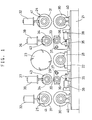
- Figs. 1 through 3 show a device for planing wooden plates embodying the invention.
- This device comprises a plate support roll 22 (that is, the reaction force bearing) provided on a base 21 at its center, a planing cylinder 23 (or cutter) provided right over and opposite the plate support roll 21, front and rear feed units 24, 25 provided in front (with respect to the feed direction of a plate A) and rear of the planing cylinder 23 and having vertically arranged rolls into which the plate A is inserted, and front and rear movable bodies 26, 27 comprising vertically arranged rolls between which the plate A is caught.
- the plate gripping portions between the plate support roll 22 and the planing cylinder 23, those of the frond and rear feed units 24, 25, and those of the front and rear movable bodies 26, 27 are aligned with each other along the feed line of the plate A.
- the plate support roll 22 has both ends thereof supported by bearings 28 fixed to the base 21 so as to be rotatable, and serves as a reaction force bearing.
- the planing cylinder 23 disposed right over the plate support roll 22 carries a plurality of planing blades 29 on its circumferential surface, and rotates while keeping a predetermined distance from the plate support roll 22.
- the front and rear feed units 24 and 25 are identical in structure. So the same elements are denoted by the same numerals. They comprise a motor-driven lower roll 30 rotatably supported at both ends by bearings 40 fixed to the base 21, and a motor-driven upper roll 31 vertically movably provided right over the lower roll 30 and rotatably supported at both ends by bearings 41.
- the upper roll 31 is urged downward by urging means such as a hydraulic cylinder 32 or pulse motors, or by springs.
- a plate A is caught between the upper and lower rolls 30, 31 and fed at a constant speed.
- the front and rear movable bodies 26, 27 are identical in structure, so the same elements are denoted by the same numerals. They comprise a vertically pivotable lower roll 33 and a vertically movable upper roll 34 provided right over the lower roll 33. Tumbled L-shaped swing arms 36 have their bases pivotally supported on a pivot 37. The lower roll 33 is rotatably supported on the upper leg of the arm 36 at one end. The arms 36 have the other ends coupled to the rods of hydraulic cylinders 38 fixed to the base 21. By extending and retracting the cylinders 38, the lower rolls 33 are vertically pivoted about the pivot 37.
- the upper rolls 34 have both ends thereof rotatably supported by bearings 43, and are urged downward by hydraulic cylinders 39 or springs. A plate A is gripped between the upper and roller rolls.
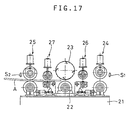
- Figs. 15 through 17 show in sequence the method of controlling the rolls of the planing device of the first embodiment.
- Fig. 15A shows the state before the plate A is fed.
- the plate detector switches S1 and S2 at the inlet and outlet are both off.
- the upper roll 31 of the front feed unit 24 is in its lowered position.
- the upper rolls of the front and rear movable bodies 26, 27 and the rear feed unit 25 are in their raised position.
- the inlet plate detector switch S1 When a plate A is fed into between the upper and lower rolls 30 and 31 of the front feed unit 24 with the cylinder 23 and the upper and lower rolls 30, 31 of the front and rear feed units 24, 25 rotating as shown in Fig. 15, the inlet plate detector switch S1 is turned on, and the upper roll 34 of the front movable body 26 lowers to a lowered position while the upper roll 31 of the front feed unit 24 remains at its lowered position, with the upper roll 34 of the rear movable body 27 and the upper roll 31 of the rear feed unit 25 remaining at the raised position, and the outlet plate detector switch S2 off.
- the plate A is thus fed and caught between the upper and lower rolls 33, 34 of the front movable body 26, so that it is pressed down a predetermined distance or interference, and is fed into between the support roll 22 and the planing cylinder 23.
- the plate A is fed while being caught between the upper and lower rolls 33, 34 of the front movable body 26 and urged by a predetermined interference downwardly from the feed surface connecting the lower roll 30 of the front feed unit 24 and the support roll 22.
- the leading end of the plate A reaches the support roll 22, it thus rides onto the support roll 22, so that the plate A is bent or deflected downward between the support roll 22 and the lower roll 30 of the front feed unit 24.
- the plate A is reliably kept pressed against the support roll 22 into line contact therewith. This prevents floating of the plate A when its leading end enters into between the support roll 22 and the planing cylinder 23.
- the plate A passes between the support roll 22 and the planing cylinder 23, its surface is cut or smoothened by the rotating planing cylinder 23.
- the leading end of the plate A is then fed to the rear movable body 27 and the rear feed unit 25.
- the plate A is reliably brought into line contact with the support roll 22 at its front and rear ends without floating. It is thus possible to prevent the formation of depressions in the plate near its front and rear ends.
- Fig. 17 shows a state when the rear end of the plate A has passed the planing cylinder 23. Any parts maintain the same position as in Fig. 16B. When the rear end of the plate A passes the outlet plate detector switch S2 and the switch is turned off, each part returns to the position shown in Fig. 15A.
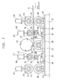
- Figs. 4 through 6 show a cutting device of a second embodiment.
- the mechanism of the first embodiment is used to finish the plate A so that its thickness will be uniform over the entire length.
- the same numerals are used to the same elements as in the first embodiment and description is omitted.
- the bearing 28 supporting the support roll 22 is movable in the feed direction of plate A along a guide 47 provided on the base 21.
- the swing arms 36 provided in front and rear of the bearing 28 have their bottom ends coupled with the bearing 28 by links 42 so that the support roll 22 will move back and forth when the lower rolls 33 of the front and rear movable bodies 26, 27 move up and down.
- Cylinders 38 for the front and rear movable bodies 26, 27 push the other ends of the link-coupling portions of the swing arms 36 in opposite directions to balance the swing arms 36.
- the cutting device of the second embodiment cuts a plate A in substantially the same way as the cutting device of the first embodiment.
- the front and rear movable bodies 26, 27 deflect the plate A downwardly by a predetermined distance between the support roll 22 and the front feed unit 24 when its front end is inserted into between the support roll 22 and the planing cylinder 23, and between the support roll 22 and the rear feed unit 25 when its front end has reached the rear feed unit 25.
- the plate A when the front end of the plate A passes the front movable member 26, the plate A is pressed down a predetermined distance by the cylinder 39, so that the swing arms 36 pivot about the pivot shaft 37 by a distance corresponding to the distance by which the plate A has been pressed down.
- the support roll 22 is thus moved rearwardly through the links 42, so that the contact point between the support roll 22 and the plate A also moves rearwardly.
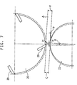
- Fig. 7 shows the relation between the contact point between the support roll 22 and the plate A and the planing cylinder 23. If with the axis of the cylinder 23 aligned with the axis of the support roll 22 the plate A is deflected by a predetermined distance downwardly for the distance c between the support roll 22 and the circle circumscribing the planing blades 29, the contact point d between the support roll 22 and the plate A moves an angle ⁇ backward (with respect to the feed direction) with respect to the vertical line containing the axis of the support roll 22 and the axis of the cylinder 23, so that when the plate A moves into between the planing cylinder 23 and the support roll 22, it is inclined an angle b with respect to the horizontal line.
- the thickness c of the finished plate will be thinner than when it is fed completely horizontally.
- the switch S1 When the plate A passes the inlet-side plate detector switch S1 and is fed into the front feed unit 24, the switch S1 is turned on. Since the front movable body 26 is lowered to its lowered position, when the plate A reaches the front movable body 26, it is pressed down a predetermined distance, so that the swing arms 36 pivot a predetermined angle. As a result, the support roll 22 moves rearwardly, so that the axis of the support roll 22 is moved to a position behind of the axis of the planing cylinder 23. But the contact point between the support roll 22 and the plate A is located right under the planing cylinder 23.
- the plate A is fed while being cut by the planing cylinder 23.
- the latter switch is turned on, so that the rear movable body 27 and the rear feed unit 25 are lowered to their lower positions.
- the plate A is pressed down a predetermined distance by the rear movable body 27, so that the swing arms 36 pivot and the support roll 22 moves in a reverse direction, that is, forward.
- Balance is thus maintained with the axes of the planing cylinder 23 and support roll 22 aligned with each other and the contact point between the support roll 22 and the plate A located right under the planing cylinder 23.
- the plate A is fed further while being cut.
- the inlet-side plate member detector switch When the rear end of the plate A passes the inlet-side plate member detector switch, the latter switch is turned off, and the front feed unit 24 and the front movable body 26 rise to their raised positions, so that the pressure on the plate A by the front movable body 26 is released. The abovementioned balance is thus lost, so that the swing arm 36 of the rear movable body 27 pivots further.
- the support roll 22 is moved forward, so that the vertical axis of the support roll 22 moves ahead of the vertical axis of the planing cylinder 23. But the contact point between the support roll 22 and the plate A is located right under the planing cylinder 23, so that the plate A can be finished to a predetermined thickness after cutting.
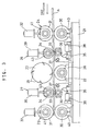
- Figs. 8 through 10 show a cutting device of the third embodiment.
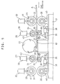
- a stationary member is used as a reaction force bearing. It may be a surface plate which is narrow in its width perpendicular to the feed direction of the plate A so as to be able to support the bottom of the plate A at a position right under the axis of the planing cylinder 23. Otherwise, as shown, it may be a fixed support table 61. A projection having a top surface perpendicular to the feed direction of the plate at a position right under the vertical axis of the planing cylinder and having a triangular section is arranged as its apex. In front of this fixed support plate 61, the front feed unit 24 and the front movable body 26 are provided. In its rear, the rear feed unit 25 and the rear movable body 27 are provided.
- the plate A is deflected supported at three points to cut it in substantially the same manner as in the first embodiment.
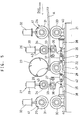
- Fig. 11 shows a cutting device of a fourth embodiment in which the lower rolls 33 of the front movable body 26 and the rear movable body 27 of the third embodiment are omitted. Even though the lower rolls 33 for supporting the underside of the plate A are omitted, if it is thick enough, it is a rigid member, so that it is possible to deflect the plate A while supporting it at three points. Thus, the plate A can be cut in substantially the same manner as in the first embodiment.
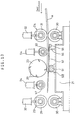
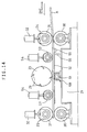
- Figs. 12 through 14 show a cutting device of the fifth embodiment in which instead of the support roll 22 of the first embodiment, a pivotable plate member support plate is used as a reaction force bearing.
- the cutting device of the fifth embodiment has a plate support plate 52 provided under a planing cylinder 23 which rotates at a fixed position, so as to extend in the feed direction of the plate and be pivotable about a pivot shaft 51.
- a plate support plate 52 provided under a planing cylinder 23 which rotates at a fixed position, so as to extend in the feed direction of the plate and be pivotable about a pivot shaft 51.
- front and rear feed units 24, 25 are provided which grip a plate A between vertically arranged rolls.
- front and rear movable body 53 and 57 are provided over the plate support plate 52 to grip the plate A between the respective bodies and the plate support plate 52.
- the plate support plate 52 is elongated in the feed direction of the plate A and is made of a material flexible enough to be deflectable along the plate. It is fixed at its bottom center to a pivot shaft 51 which has its both ends rotatably supported on pivot shaft bearings 58 mounted on the base 21, so as to be pivotable about the pivot shaft 51.
- a weight 55 mounted to its bottom at one end thereof from which the plate A enters keeps the plate 52 inclined by an angle limited by a pin 56 provided on the base 21 so as to slope downward toward its plate-entering end.
- the front movable body 53 and the rear movable body 57 have movable rollers that are urged downward by hydraulic cylinders 54 or springs to grip the plate A between the rollers and the plate support plate 52.
- the inlet-side plate detector switch turns on and the front movable body 53 lowers to its lowered position. In this state, the leading end of the plate A is slid on the inclined plate support plate 52. When its front end passes the front movable body 53, it is gripped between the front movable body 53 and the plate support plate 52 and fed while being pressed down a predetermined distance.
- the plate A When the front end of the plate A reaches the point right over the center of the support shaft 51, the plate A is fed while being deflected downward between the lower roll 30 of the front feed unit 24 and the portion of the plate support plate 52 right over the center of the pivot shaft 51, so that the front end of the plate A is fed while being pressed reliably against the plate support plate 52.
- the plate A is fed between the plate support plate 52 and the planing cylinder 23 while being cut by the planing cylinder 23, and then fed into the rear movable body 57 and rear feed unit 25.
- the rear movable body 57 and the rear feed unit 25 lower to their lowered positions, so that the plate A is gripped between the rear movable body 57 and the plate support plate 52.
- the plate is thus fed while being pressed down a predetermined distance. It is deflected downward between the portion of the plate support plate 52 right over the center of the pivot shaft 51 and the lower roll 30 of the rear feed unit 25.
- the rear end of the plate A is fed while being pressed reliably against the plate support plate 52, so that it is possible to prevent floating when the rear end of the plate A passes between the planing cylinder 23 and the plate support plate 52.
- the plate Since the plate is pressed down a predetermined distance by the lower rolls 30 of the front and rear feed units 24, 25 between the portion of the plate support plate 52 right over the center of the pivot shaft 51 and the front and rear feed units 24, 25 and supported at three points, the plate A is deflected about the portion of the plate support plate 52 right over the center of the pivot shaft 51. Since the plate support plate 52 is flexible, it is deflected together with the plate A, so that the plate A is pressed reliably against the plate support plate 52 at its front and rear ends. Thus, it is possible to prevent floating and thus the formation of depressions on the plate A near its front and rear ends.
- the pivot shaft 51 may be movable in the feed direction of the plate A, so that when the plate A is deflected, the plate support plate may be adapted to be moved forward or backward.
- the plate A By deflecting the plate A by a predetermined amount, it can be reliably brought into contact with the plate support plate 52 at its front and rear ends, so that it is possible to prevent floating. Thus, the formation of depressions in the plate A near its front and rear ends can be prevented.
- cutting devices of the embodiments are all planing machines having planing cylinders
- sanders for automatically cutting the surface of a plate may be used instead of planing cylinders.
- reaction force bearing is provided right under the planing cylinder
- the former may be provided right over the latter.
- roll type structures are used as front and rear feed units 24, 25, endless ways such as conveyors may be used.
- a plate is deflected while supporting it at three points to keep it pressed against the reaction force bearing during cutting.
- the front and rear ends of the plate member will never float, so that it is possible to prevent the formation of depressions in the plate during cutting.
- Deflection is applied by the rolls that are rotatable, so that because conventional pressure bar or chip breaker is not necessary, resistance to the feed of the plate is small, so that power of feed can be saved.
Landscapes
- Life Sciences & Earth Sciences (AREA)
- Engineering & Computer Science (AREA)
- Mechanical Engineering (AREA)
- Wood Science & Technology (AREA)
- Forests & Forestry (AREA)
- Milling, Drilling, And Turning Of Wood (AREA)
- Veneer Processing And Manufacture Of Plywood (AREA)
Applications Claiming Priority (2)
| Application Number | Priority Date | Filing Date | Title |
|---|---|---|---|
| JP24984998 | 1998-09-03 | ||
| JP24984998A JP3795680B2 (ja) | 1998-09-03 | 1998-09-03 | 板材の切削方法及びその装置 |
Publications (3)
| Publication Number | Publication Date |
|---|---|
| EP0983828A2 true EP0983828A2 (de) | 2000-03-08 |
| EP0983828A3 EP0983828A3 (de) | 2000-12-06 |
| EP0983828B1 EP0983828B1 (de) | 2004-06-09 |
Family
ID=17199107
Family Applications (1)
| Application Number | Title | Priority Date | Filing Date |
|---|---|---|---|
| EP99117051A Expired - Lifetime EP0983828B1 (de) | 1998-09-03 | 1999-08-30 | Verfahren und Vorrichtung zum Schneiden von Holzplatten |
Country Status (5)
| Country | Link |
|---|---|
| US (1) | US6247511B1 (de) |
| EP (1) | EP0983828B1 (de) |
| JP (1) | JP3795680B2 (de) |
| DE (1) | DE69917847T2 (de) |
| TW (1) | TW411300B (de) |
Families Citing this family (25)
| Publication number | Priority date | Publication date | Assignee | Title |
|---|---|---|---|---|
| DE10009155A1 (de) * | 2000-02-26 | 2001-10-11 | Weinig Michael Ag | Maschine zum Bearbeiten von Werkstücken aus Holz, Kunststoff und dergleichen, insbesondere Kehlmaschine, sowie Verfahren zur Einstellung einer solchen Maschine |
| US6571839B2 (en) * | 2000-03-14 | 2003-06-03 | The Coe Manufacturing Company | Automatic press roll control |
| CA2384548C (en) * | 2002-05-02 | 2010-02-16 | Les Produits Gilbert Inc. | Automated planer machine |
| CA2460086C (en) * | 2003-03-13 | 2011-07-05 | Ronald W. Mcgehee | Optimizing planer system and method |
| US7299837B2 (en) * | 2005-10-31 | 2007-11-27 | Les Produits Gilbert, Inc. | Planing heads assembly for an automated planing machine |
| US7874130B2 (en) * | 2007-03-06 | 2011-01-25 | Darifill Inc. | Ice cream sandwich-making machine |
| CA2636544C (en) * | 2007-07-05 | 2014-07-08 | Osi Machinerie Inc. | Floor planks production machine and method |
| KR101290362B1 (ko) * | 2011-06-28 | 2013-07-26 | 현대제철 주식회사 | 박판 소재 전단 장치 |
| US9248516B2 (en) * | 2011-11-23 | 2016-02-02 | Newman Machines Company, Inc. | Planing device and method |
| CN102862239B (zh) * | 2012-09-25 | 2015-09-09 | 刘鸿彬 | 硅棒旋转浮动切割数控机床 |
| WO2014074023A2 (ru) * | 2012-11-12 | 2014-05-15 | Oparin Vladimir Vladimirovich | Станок для обработки изделий из древесины поперек волокон в трех плоскостях различных поперечных сечений |
| RU2516781C1 (ru) * | 2012-11-12 | 2014-05-20 | Владимир Владимирович Опарин | Способ обработки изделий из древесины поперек волокон в двух и более плоскостях различных форм поперечных сечений |
| DE102014016628A1 (de) * | 2014-11-04 | 2016-05-04 | Michael Weinig Ag | Verfahren zur Überwachung des Maschinenraumes einer Bearbeitungsmaschine, vorzugsweise einer Kehlmaschine, sowie Bearbeitungsmaschine, insbesondere Kehlmaschine, zur Durchführung eines solchen Verfahrens |
| KR101729697B1 (ko) | 2015-03-16 | 2017-04-25 | 한국건설기술연구원 | 섬유판재 제조장치 |
| CN105329639B (zh) * | 2015-11-23 | 2017-11-24 | 四川省青城机械有限公司 | 双联浮动式上压辊机构 |
| CN105235019B (zh) * | 2015-11-23 | 2017-06-06 | 四川省青城机械有限公司 | 气缸浮动式双主动辊送料机构 |
| KR101945359B1 (ko) * | 2016-03-03 | 2019-02-07 | 강재식 | 깔창과 슬리퍼, 이의 제조 장치 및 방법 |
| DE102016013408A1 (de) * | 2016-11-04 | 2018-05-30 | Michael Weinig Ag | Maschine und Verfahren zur Bearbeitung von Werkstücken aus Holz, Kunststoff und dgl. |
| CN106926323A (zh) * | 2017-03-10 | 2017-07-07 | 杨发明 | 用于加工竹展平板的双面刨床 |
| CN107042434B (zh) * | 2017-05-03 | 2019-02-19 | 华南农业大学 | 一种砧板自动填缝打磨机 |
| CN107627164A (zh) * | 2017-10-20 | 2018-01-26 | 南充市龙煌建材有限公司 | 再生木板砂光机 |
| CN107756163B (zh) * | 2017-11-18 | 2019-09-03 | 台州市黄岩赵兴工艺品有限公司 | 一种木材板打磨装置 |
| CN111086071B (zh) * | 2018-10-24 | 2021-11-26 | 株式会社名南制作所 | 单板移动装置 |
| CN113103394B (zh) * | 2019-07-15 | 2023-12-08 | 漳州市龙文区悦丰木业有限公司 | 一种智能型木质家具制造工艺 |
| CN112025449A (zh) * | 2020-09-19 | 2020-12-04 | 董前友 | 一种板材传送打磨装置 |
Family Cites Families (14)
| Publication number | Priority date | Publication date | Assignee | Title |
|---|---|---|---|---|
| US2102186A (en) * | 1936-07-20 | 1937-12-14 | Stetson Ross Machine Company | Wood planing machine |
| US2679871A (en) * | 1950-07-19 | 1954-06-01 | Robert S Ford | Work holder for jointer planers and other woodworking machines |
| US2642902A (en) * | 1951-05-04 | 1953-06-23 | Carey Eric Lee | Planing attachment for jointers |
| US3082802A (en) * | 1958-03-13 | 1963-03-26 | Dickson George | Method of and apparatus for forming pulping chips incident to lumber finishing |
| SU368026A1 (ru) * | 1971-06-28 | 1973-01-26 | Подающий механизм к деревообрабатывающему | |
| US3990568A (en) * | 1975-11-24 | 1976-11-09 | Weyerhaeuser Company | Press roll system for sawing machine |
| US4031932A (en) * | 1976-06-28 | 1977-06-28 | Leasure Edgar F | Planing attachment for jointers |
| US4457350A (en) * | 1980-07-03 | 1984-07-03 | Finnila John S | Lumber planing machine |
| US4438795A (en) * | 1982-04-22 | 1984-03-27 | Kimwood Corporation | Flexible platen planer |
| US4724877A (en) * | 1987-04-10 | 1988-02-16 | Cemco Volunteer Associates | Self centering planer apparatus |
| DE4017991A1 (de) * | 1990-06-05 | 1991-12-12 | Hoffmann & Kuehnhenrich Gmbh | Verfahren zum spanabhebenden bearbeiten von rohlingen aus holz oder aehnlichen werkstoffen wie bspw. kunststoff |
| JPH05177602A (ja) * | 1992-01-07 | 1993-07-20 | Taihei Mach Works Ltd | 木材切削方法ならびに装置 |
| US5368077A (en) * | 1993-09-22 | 1994-11-29 | U.S. Natural Resources, Inc. | Zero lead planer |
| US5396938A (en) * | 1993-12-17 | 1995-03-14 | Boring Machine Works, Inc. | Apparatus and method for producing surfaced lumber |
-
1998
- 1998-09-03 JP JP24984998A patent/JP3795680B2/ja not_active Expired - Lifetime
-
1999
- 1999-08-30 DE DE69917847T patent/DE69917847T2/de not_active Expired - Lifetime
- 1999-08-30 EP EP99117051A patent/EP0983828B1/de not_active Expired - Lifetime
- 1999-09-01 US US09/387,551 patent/US6247511B1/en not_active Expired - Lifetime
- 1999-09-02 TW TW088115092A patent/TW411300B/zh active
Also Published As
| Publication number | Publication date |
|---|---|
| US6247511B1 (en) | 2001-06-19 |
| DE69917847T2 (de) | 2005-06-30 |
| TW411300B (en) | 2000-11-11 |
| JP3795680B2 (ja) | 2006-07-12 |
| DE69917847D1 (de) | 2004-07-15 |
| EP0983828B1 (de) | 2004-06-09 |
| EP0983828A3 (de) | 2000-12-06 |
| JP2000071204A (ja) | 2000-03-07 |
Similar Documents
| Publication | Publication Date | Title |
|---|---|---|
| EP0983828B1 (de) | Verfahren und Vorrichtung zum Schneiden von Holzplatten | |
| JP7365044B2 (ja) | 鉄筋切断装置及び鉄筋切断方法 | |
| US4420124A (en) | Carpet rolling machine | |
| CN214562352U (zh) | 一种pvc淋水片切边机 | |
| KR900006225B1 (ko) | 스핀들리스 베니어선반 | |
| JPH0678140B2 (ja) | 多軸タレット巻取機の巻方向自動切替装置及び巻取自動切替方法 | |
| CN209478265U (zh) | 一种裁切装置 | |
| KR100788176B1 (ko) | 목재패널의 엣지테잎 커팅장치 | |
| KR20030005498A (ko) | 에지밴딩기의 코너트리밍장치 | |
| KR200263270Y1 (ko) | 에지밴딩기의 코너트리밍장치 | |
| US4359303A (en) | Plate-edge machining apparatus | |
| US20040163437A1 (en) | Roll forming apparatus for forming sheet material into multiple shapes | |
| JP3092906B2 (ja) | ラップ材の貼着装置 | |
| CN214243198U (zh) | 一种卷装木板放料机 | |
| JP2515633B2 (ja) | ウェブ巻取機用切断装置 | |
| JP3386681B2 (ja) | 切断機の定寸送り装置 | |
| JP2594787Y2 (ja) | シャーリングマシン | |
| JPS5940974Y2 (ja) | シヤ−リングマシンの端材押出し装置 | |
| JP4251948B2 (ja) | 物品の方向転換装置 | |
| JPH039939Y2 (de) | ||
| JPH0753765Y2 (ja) | 帯板コイルの帯板先端部曲げ装置 | |
| SU1207760A2 (ru) | Устройство дл продольной резки рулонных материалов | |
| JPH0436630Y2 (de) | ||
| JPH07156104A (ja) | 木工機械のプレッシャローラ装置、サイドローラ装置、安全装置 | |
| JPH0579478B2 (de) |
Legal Events
| Date | Code | Title | Description |
|---|---|---|---|
| PUAI | Public reference made under article 153(3) epc to a published international application that has entered the european phase |
Free format text: ORIGINAL CODE: 0009012 |
|
| AK | Designated contracting states |
Kind code of ref document: A2 Designated state(s): DE IT SE |
|
| AX | Request for extension of the european patent |
Free format text: AL;LT;LV;MK;RO;SI |
|
| PUAL | Search report despatched |
Free format text: ORIGINAL CODE: 0009013 |
|
| AK | Designated contracting states |
Kind code of ref document: A3 Designated state(s): AT BE CH CY DE DK ES FI FR GB GR IE IT LI LU MC NL PT SE |
|
| AX | Request for extension of the european patent |
Free format text: AL;LT;LV;MK;RO;SI |
|
| RIC1 | Information provided on ipc code assigned before grant |
Free format text: 7B 27C 1/12 A, 7B 27C 1/04 B |
|
| 17P | Request for examination filed |
Effective date: 20010214 |
|
| AKX | Designation fees paid |
Free format text: DE IT SE |
|
| GRAP | Despatch of communication of intention to grant a patent |
Free format text: ORIGINAL CODE: EPIDOSNIGR1 |
|
| GRAS | Grant fee paid |
Free format text: ORIGINAL CODE: EPIDOSNIGR3 |
|
| GRAA | (expected) grant |
Free format text: ORIGINAL CODE: 0009210 |
|
| AK | Designated contracting states |
Kind code of ref document: B1 Designated state(s): DE IT SE |
|
| REF | Corresponds to: |
Ref document number: 69917847 Country of ref document: DE Date of ref document: 20040715 Kind code of ref document: P |
|
| REG | Reference to a national code |
Ref country code: SE Ref legal event code: TRGR |
|
| PLBE | No opposition filed within time limit |
Free format text: ORIGINAL CODE: 0009261 |
|
| STAA | Information on the status of an ep patent application or granted ep patent |
Free format text: STATUS: NO OPPOSITION FILED WITHIN TIME LIMIT |
|
| 26N | No opposition filed |
Effective date: 20050310 |
|
| PGFP | Annual fee paid to national office [announced via postgrant information from national office to epo] |
Ref country code: SE Payment date: 20140821 Year of fee payment: 16 |
|
| PGFP | Annual fee paid to national office [announced via postgrant information from national office to epo] |
Ref country code: IT Payment date: 20140827 Year of fee payment: 16 |
|
| PGFP | Annual fee paid to national office [announced via postgrant information from national office to epo] |
Ref country code: DE Payment date: 20141024 Year of fee payment: 16 |
|
| REG | Reference to a national code |
Ref country code: DE Ref legal event code: R082 Ref document number: 69917847 Country of ref document: DE |
|
| REG | Reference to a national code |
Ref country code: DE Ref legal event code: R119 Ref document number: 69917847 Country of ref document: DE |
|
| REG | Reference to a national code |
Ref country code: SE Ref legal event code: EUG |
|
| PG25 | Lapsed in a contracting state [announced via postgrant information from national office to epo] |
Ref country code: IT Free format text: LAPSE BECAUSE OF NON-PAYMENT OF DUE FEES Effective date: 20150830 |
|
| PG25 | Lapsed in a contracting state [announced via postgrant information from national office to epo] |
Ref country code: SE Free format text: LAPSE BECAUSE OF NON-PAYMENT OF DUE FEES Effective date: 20150831 |
|
| PG25 | Lapsed in a contracting state [announced via postgrant information from national office to epo] |
Ref country code: DE Free format text: LAPSE BECAUSE OF NON-PAYMENT OF DUE FEES Effective date: 20160301 |