EP0983877A2 - Appareil de contrôle de la pression de l'air de pneumatiques d'un véhicule automobile - Google Patents
Appareil de contrôle de la pression de l'air de pneumatiques d'un véhicule automobile Download PDFInfo
- Publication number
- EP0983877A2 EP0983877A2 EP19990116644 EP99116644A EP0983877A2 EP 0983877 A2 EP0983877 A2 EP 0983877A2 EP 19990116644 EP19990116644 EP 19990116644 EP 99116644 A EP99116644 A EP 99116644A EP 0983877 A2 EP0983877 A2 EP 0983877A2
- Authority
- EP
- European Patent Office
- Prior art keywords
- motor vehicle
- vehicle wheel
- sound absorber
- sensor unit
- support body
- Prior art date
- Legal status (The legal status is an assumption and is not a legal conclusion. Google has not performed a legal analysis and makes no representation as to the accuracy of the status listed.)
- Withdrawn
Links
- 238000012544 monitoring process Methods 0.000 title 1
- 239000006096 absorbing agent Substances 0.000 claims abstract description 44
- 230000002787 reinforcement Effects 0.000 claims description 13
- 239000000853 adhesive Substances 0.000 claims description 4
- 230000001070 adhesive effect Effects 0.000 claims description 4
- 239000004677 Nylon Substances 0.000 claims description 3
- 239000004760 aramid Substances 0.000 claims description 3
- 229920003235 aromatic polyamide Polymers 0.000 claims description 3
- 229920001778 nylon Polymers 0.000 claims description 3
- 229920000728 polyester Polymers 0.000 claims description 3
- 238000005728 strengthening Methods 0.000 claims description 3
- 239000011324 bead Substances 0.000 description 9
- 239000006260 foam Substances 0.000 description 6
- 230000003014 reinforcing effect Effects 0.000 description 5
- 230000005540 biological transmission Effects 0.000 description 3
- 229920001971 elastomer Polymers 0.000 description 2
- 239000000806 elastomer Substances 0.000 description 2
- 230000001939 inductive effect Effects 0.000 description 2
- 239000007787 solid Substances 0.000 description 2
- 206010039203 Road traffic accident Diseases 0.000 description 1
- 230000009172 bursting Effects 0.000 description 1
- 239000002131 composite material Substances 0.000 description 1
- 230000008878 coupling Effects 0.000 description 1
- 238000010168 coupling process Methods 0.000 description 1
- 238000005859 coupling reaction Methods 0.000 description 1
- 230000007423 decrease Effects 0.000 description 1
- 230000005672 electromagnetic field Effects 0.000 description 1
- 238000004519 manufacturing process Methods 0.000 description 1
Images
Classifications
-
- B—PERFORMING OPERATIONS; TRANSPORTING
- B60—VEHICLES IN GENERAL
- B60C—VEHICLE TYRES; TYRE INFLATION; TYRE CHANGING; CONNECTING VALVES TO INFLATABLE ELASTIC BODIES IN GENERAL; DEVICES OR ARRANGEMENTS RELATED TO TYRES
- B60C23/00—Devices for measuring, signalling, controlling, or distributing tyre pressure or temperature, specially adapted for mounting on vehicles; Arrangement of tyre inflating devices on vehicles, e.g. of pumps or of tanks; Tyre cooling arrangements
- B60C23/02—Signalling devices actuated by tyre pressure
- B60C23/04—Signalling devices actuated by tyre pressure mounted on the wheel or tyre
-
- B—PERFORMING OPERATIONS; TRANSPORTING
- B60—VEHICLES IN GENERAL
- B60C—VEHICLE TYRES; TYRE INFLATION; TYRE CHANGING; CONNECTING VALVES TO INFLATABLE ELASTIC BODIES IN GENERAL; DEVICES OR ARRANGEMENTS RELATED TO TYRES
- B60C17/00—Tyres characterised by means enabling restricted operation in damaged or deflated condition; Accessories therefor
- B60C17/04—Tyres characterised by means enabling restricted operation in damaged or deflated condition; Accessories therefor utilising additional non-inflatable supports which become load-supporting in emergency
-
- B—PERFORMING OPERATIONS; TRANSPORTING
- B60—VEHICLES IN GENERAL
- B60C—VEHICLE TYRES; TYRE INFLATION; TYRE CHANGING; CONNECTING VALVES TO INFLATABLE ELASTIC BODIES IN GENERAL; DEVICES OR ARRANGEMENTS RELATED TO TYRES
- B60C19/00—Tyre parts or constructions not otherwise provided for
- B60C19/002—Noise damping elements provided in the tyre structure or attached thereto, e.g. in the tyre interior
-
- B—PERFORMING OPERATIONS; TRANSPORTING
- B60—VEHICLES IN GENERAL
- B60C—VEHICLE TYRES; TYRE INFLATION; TYRE CHANGING; CONNECTING VALVES TO INFLATABLE ELASTIC BODIES IN GENERAL; DEVICES OR ARRANGEMENTS RELATED TO TYRES
- B60C19/00—Tyre parts or constructions not otherwise provided for
- B60C2019/006—Warning devices, e.g. devices generating noise due to flat or worn tyres
Definitions
- the invention relates to a motor vehicle wheel with a rim on which a tire is mounted is, wherein a sensor unit is arranged in the torus of the tire.
- the sensor unit sends data to a central unit and also receives if necessary Data from this.
- the Sensor unit is an air pressure control device, but it will expressly pointed out that the invention is not restricted to this.
- the correct adjustment of the air pressure of motor vehicle wheels is important with regard to different aspects.
- too high or too low air pressure leads to increased tire wear, so that the motor vehicle tires have to be replaced prematurely, which causes unnecessary costs.
- an excessively low air pressure poses a considerable safety risk, since it causes increased flexing work on the tire flanks, which leads to a sharp increase in the temperature of the motor vehicle tire.
- the strength of the tire flanks decreases significantly, leading to a Bursting "of the motor vehicle tire and thus, particularly at high speeds, can lead to serious traffic accidents.
- air pressure control devices which automatically measure the air pressure of motor vehicle tires and at least one critical deviation from a target air pressure to the measured air pressure Send the corresponding signal to a central unit.
- the central unit reports the too low air pressure to the driver.
- the air pressure control devices can be arranged in different ways in the toroidal area of the tire become.
- the invention has for its object to provide a motor vehicle wheel in whose toroidal area a sensor unit can be attached in a simple manner can.
- a sound absorber or Emergency running support body is located, in which the sensor unit is embedded or on which the Sensor unit is attached.
- the sound absorber or is preferably Emergency running support body attached to the rim of the motor vehicle wheel.
- the basic idea of the invention is that the sensor unit on one Element is attached or embedded in this, which in modern Motor vehicle wheels is arranged in the toroidal area of the tire anyway.
- the advantages achieved by the invention can be seen in particular in that the Sensor unit with little effort in the sound absorber or Emergency run support body can be embedded or attached to this. That's the way it is for example, it is possible to design the sound absorber as a foam body which the sensor unit is embedded. It is also possible to use the Form emergency run support body as a solid elastomer component, in which the Sensor unit is embedded. Another advantage of the invention is that that especially in the case where the sensor unit in the sound absorber or is embedded in the emergency running support body, with respect to the shape of the Housing of the sensor unit is independent, since the sensor unit is not flush certain interfaces, the shape of which is specified, must be present.
- the shape of the housing with a view to optimal transmission and To optimize the reception performance of the sensor unit.
- Another advantage of the invention can be seen in the fact that one in a sound absorber or emergency support body embedded sensor unit can have a high weight, since the one Rotation of the motor vehicle wheel on the centrifugal forces acting on the sensor unit from the elements mentioned. It is therefore possible to Sensor unit for permanent energy supply with a high capacity battery to provide.
- the advantages mentioned are achieved without the functionality of the Sound absorber or the emergency support body to be significantly restricted.
- the sound absorber or the emergency running support body is of this type trained so that it does not hinder the mounting of the tire on the fig.
- Corresponding training of a sound absorber or an emergency running support body are known to the person skilled in the art, so that no further details are given here to be received.
- the fig can consist of two parts, during assembly of the tire on the rim, first a bead on part of the rim and the other tire bead is mounted on the other part of the rim and the two Rim components are then connected together.
- Such a structure is can be found, for example, in truck figs and is also known to the expert well known, so that it is not discussed in more detail here are needed.
- the Sound absorber or the emergency support body the low bed in a ring.
- the advantage of this Further training can be seen in the fact that through the sound absorber or Emergency running support body with no rotational imbalance arise.
- Another advantage is the fact that with such Training the sound absorber or the emergency support body an optimal Functionality of these elements can be guaranteed.
- the motor vehicle wheel contains a counterweight on the side radially opposite the sensor unit in order to compensate for the imbalance caused by the sensor unit.
- the balance weight is embedded in the sound absorber or emergency support body or attached to it.
- the advantage of this development can be seen in the fact that the balance weight required for the sensor unit can be embedded in or attached to the elements mentioned already during the manufacture of the sound absorber or the emergency running support body.
- the balancing weight is preferably attached or embedded in the same radial and axial position on the sound absorber or on the emergency running support body.
- the counterweight analog "to the air pressure control device, ie have the same outer shape and the same density.
- the Sound absorber a reinforcing tape that runs around in its circumferential direction.
- the advantage of this training is the fact that Strengthening tape, the stability of the sound absorber is guaranteed, because of the reinforcement band acting on the sound absorber centrifugal forces can be included.
- the reinforcement tape covers the radially outer surface of the sound absorber.
- the Reinforcement tape non-metallic reinforcement e.g. B. made of nylon, polyester or aramid.
- the strength members can optionally be made of an elastomer Be surrounded by the coat.
- the sensor unit in a recess of the sound absorber embedded by the Strengthening tape is covered.
- the advantage of this training is there too see that the sensor unit only in the recess of the sound absorber needs to be inserted, which simplifies assembly.
- a balance weight on the radially opposite side of the sensor unit can also be in a Recess of the sound absorber are embedded by the reinforcement is covered. Both recesses can have the same shape as it has already been explained in connection with claim 5.
- the Sound absorber or the emergency running support body has a metallic structure which Transceiver antenna for the sensor unit is used.
- the advantage of this training can be seen in the fact that the antenna is formed over a large area and with high quality can be and that the sensor unit only requires a small housing.
- the Sensor unit can thus in a small recess of the sound absorber or Emergency running support body are embedded, the functionality of the above Do not restrict items.
- the coupling between the antenna and the Sensor unit can be inductive, capacitive or ohmic. This is the specialist known, so that it does not need to be discussed in more detail here.
- the metallic Structure e.g. B. in the form of a metallic adhesive strip on the radially outer Scope of the sound absorber or the emergency running support body arranged.
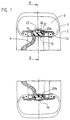
- Figure 1 shows a motor vehicle wheel 2 with a rim 4 on which a tire 6 such is mounted that the tire beads 24 encompass the rim 4 and outside the Torus space 8 of the tire 6 are arranged radially inside below the fig 4.
- the drop bed 14 is the Fig 4 not needed.
- a sound absorber 10 in the form of a Foam body attached.
- the foam body 10 encloses the deep bed 14 ring-shaped and completely fills it up.
- a sensor unit 12 In a recess 20a of the foam body 10 which is open radially to the outside a sensor unit 12 is embedded in the form of an air pressure control unit.
- the radial outer surface of the foam body 10 and the recess 20a is through a circumferential reinforcing tape 18 covered in its circumferential direction.
- the air pressure control device 12 is also supported by the reinforcing tape 18 a rotation of the motor vehicle wheel 2 held in the recess.
- the air pressure control device 12 may be glued in the recess.
- the reinforcing tape 18 contains (not shown in the figure) in Circumferential non-metallic reinforcement, z. B. made of nylon, Polyester or aramid.
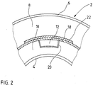
- a metallic Adhesive strips 22 are glued on (see also FIG. 2, which has a cross section along the length of the Figure 1 drawn line II / II shows).
- the metallic adhesive strip 22 serves as Antenna 22 for the air pressure control device 12 and is inductive with it, capacitive or connected via an electrical line.
- the motor vehicle wheel contains the air pressure control device 12 opposite side a balance weight 16.
- the balance weight 16 has the same axial and radial distance from the center of the wheel as that Air pressure control device 12 and is embedded in the foam body 10. Further it has the same weight and the same external shape as that Air pressure control device 12 so that the recess 20b has the same shape can have as the recess 20a.
- the balance weight 16 is also fixed in the recess 20b by the reinforcement band 18. In addition can the balance weight 16 are glued.
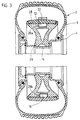
- FIG 3 shows a motor vehicle wheel 2 with a rim on which a tire 6 is mounted.
- a Emergency run support body 26 is arranged, which surrounds the rim 4 in a ring.
- the structure the emergency running body 26 is explained in detail in DE 37 20 706 A1, so that at this point should not be discussed in more detail.
- the surface of the emergency running support body contains a recess that is open radially outwards 20a, in which an air pressure control device 12 is embedded.
- the radially outer The surface of the emergency running support body 26 is supported by a stiffening ring 28 enclosed, which also closes the recess 20a. Through the stiffening ring 28, the air pressure control device 12 is fixed in the recess 20a. In addition the air pressure control device can be glued in the recess 20a.
- a balance weight 16 in the emergency running support body 26 is inserted.
- the Recess 20b is covered by the stiffening ring 28, so that Balance weight 16 is fixed in the recess 20b. In addition, that can Balance weight 16 are glued.
Landscapes
- Engineering & Computer Science (AREA)
- Mechanical Engineering (AREA)
- Measuring Fluid Pressure (AREA)
- Tires In General (AREA)
Applications Claiming Priority (2)
| Application Number | Priority Date | Filing Date | Title |
|---|---|---|---|
| DE1998139484 DE19839484A1 (de) | 1998-08-29 | 1998-08-29 | Kraftfahrzeug mit einer Luftdruckkontrollvorrichtung |
| DE19839484 | 1998-08-29 |
Publications (1)
| Publication Number | Publication Date |
|---|---|
| EP0983877A2 true EP0983877A2 (fr) | 2000-03-08 |
Family
ID=7879215
Family Applications (1)
| Application Number | Title | Priority Date | Filing Date |
|---|---|---|---|
| EP19990116644 Withdrawn EP0983877A2 (fr) | 1998-08-29 | 1999-08-26 | Appareil de contrôle de la pression de l'air de pneumatiques d'un véhicule automobile |
Country Status (2)
| Country | Link |
|---|---|
| EP (1) | EP0983877A2 (fr) |
| DE (1) | DE19839484A1 (fr) |
Cited By (4)
| Publication number | Priority date | Publication date | Assignee | Title |
|---|---|---|---|---|
| WO2002040297A1 (fr) * | 2000-11-20 | 2002-05-23 | Cristobal Olabuenaga Juan A | Cercle de prevision pour roue a pression |
| GB2438182A (en) * | 2006-05-17 | 2007-11-21 | Transense Technologies Plc | Vehicle wheel run flat safety band with sensor |
| EP2682287A1 (fr) * | 2012-07-03 | 2014-01-08 | Europlast-Nycast GmbH | Insert de roulage à plat |
| CN108274961A (zh) * | 2018-02-11 | 2018-07-13 | 泰斯福德(北京)科技发展有限公司 | 用于爆胎应急安全装置的诊断装置及爆胎应急安全装置 |
Families Citing this family (1)
| Publication number | Priority date | Publication date | Assignee | Title |
|---|---|---|---|---|
| WO2020172837A1 (fr) * | 2019-02-28 | 2020-09-03 | 何汝钊 | Moyeu de pneu de roulage à plat, pneu de roulage à plat et véhicule |
Citations (1)
| Publication number | Priority date | Publication date | Assignee | Title |
|---|---|---|---|---|
| DE19613936A1 (de) | 1996-04-06 | 1997-10-09 | Continental Ag | Befestigung einer Luftdruckkontrollvorrichtung an einem Ventil |
Family Cites Families (3)
| Publication number | Priority date | Publication date | Assignee | Title |
|---|---|---|---|---|
| US4196414A (en) * | 1978-12-13 | 1980-04-01 | Ford Motor Company | Integral tire inflation valve and tire height sensor |
| DE3720706A1 (de) * | 1987-06-23 | 1989-01-05 | Continental Ag | Pannenlauf-tragring |
| DE3736803A1 (de) * | 1987-10-30 | 1989-05-11 | Vdo Schindling | Am rad eines kraftfahrzeuges montiertes pruefelement zur ueberwachung des reifeninnendruckes |
-
1998
- 1998-08-29 DE DE1998139484 patent/DE19839484A1/de not_active Withdrawn
-
1999
- 1999-08-26 EP EP19990116644 patent/EP0983877A2/fr not_active Withdrawn
Patent Citations (1)
| Publication number | Priority date | Publication date | Assignee | Title |
|---|---|---|---|---|
| DE19613936A1 (de) | 1996-04-06 | 1997-10-09 | Continental Ag | Befestigung einer Luftdruckkontrollvorrichtung an einem Ventil |
Cited By (6)
| Publication number | Priority date | Publication date | Assignee | Title |
|---|---|---|---|---|
| WO2002040297A1 (fr) * | 2000-11-20 | 2002-05-23 | Cristobal Olabuenaga Juan A | Cercle de prevision pour roue a pression |
| GB2438182A (en) * | 2006-05-17 | 2007-11-21 | Transense Technologies Plc | Vehicle wheel run flat safety band with sensor |
| GB2438182B (en) * | 2006-05-17 | 2011-03-23 | Transense Technologies Plc | Runflat Safety Band Incorporating Wireless Device |
| US8068018B2 (en) | 2006-05-17 | 2011-11-29 | Transense Technologies Plc | Confirming the presence of a run flat safety band incorporating a wireless device |
| EP2682287A1 (fr) * | 2012-07-03 | 2014-01-08 | Europlast-Nycast GmbH | Insert de roulage à plat |
| CN108274961A (zh) * | 2018-02-11 | 2018-07-13 | 泰斯福德(北京)科技发展有限公司 | 用于爆胎应急安全装置的诊断装置及爆胎应急安全装置 |
Also Published As
| Publication number | Publication date |
|---|---|
| DE19839484A1 (de) | 2000-03-09 |
Similar Documents
| Publication | Publication Date | Title |
|---|---|---|
| DE60204862T2 (de) | Sensorbefestigungsanordnung für einen fahrzeugreifen | |
| DE69821888T2 (de) | Verfahren und Vorrichtung zum Übermitteln von gespeisten Daten und technischen Zuständen eines Reifens an einen entfernten Ort | |
| DE69315164T2 (de) | Luftreifen | |
| DE69917185T2 (de) | Lose Überwachungsvorrichtung für Reifen | |
| DE69000239T2 (de) | Fahrzeugrad aus verbundwerkstoff. | |
| EP3634782B1 (fr) | Pneumatique de véhicule | |
| WO1999064260A1 (fr) | Roue de vehicule automobile comportant un corps d'appui pour roulement de secours | |
| EP3634784B1 (fr) | Pneumatique de véhicule | |
| DE2114400A1 (de) | Sicherheitsvorrichtung fur Luft reifen | |
| EP3634783B1 (fr) | Pneumatique de véhicule | |
| EP0235364B1 (fr) | Tringle pour bandages pneumatiques | |
| EP0541040B1 (fr) | Ressort pneumatique à soufflet roulant en élastomère | |
| EP0156009B1 (fr) | Roue de véhicule automobile | |
| DE60106479T2 (de) | Sicherheitseinsatz mit eingebauter übertragungsantenne | |
| EP0983877A2 (fr) | Appareil de contrôle de la pression de l'air de pneumatiques d'un véhicule automobile | |
| DE69511780T2 (de) | Radialer Luftreifen | |
| DE1244001B (de) | Fahrzeugrad, insbesondere fuer Kraftfahrzeuge | |
| DE60226211T2 (de) | Anordung von reifen, reifenfelge und radrohling | |
| EP0683733B1 (fr) | Roue de vehicule | |
| EP1354729B1 (fr) | Dispositif pour la surveillance et l'identification de pneumatiques | |
| DE2821041C2 (fr) | ||
| EP0131117B1 (fr) | Roue pour véhicules | |
| DE102020209695A1 (de) | Abdeckende/schützende fahrzeugradnabenkappe | |
| DE4310714A1 (de) | Luftreifen | |
| DE10138410B4 (de) | Notlaufstützkörper für luftbereiftes Fahrzeugrad |
Legal Events
| Date | Code | Title | Description |
|---|---|---|---|
| PUAI | Public reference made under article 153(3) epc to a published international application that has entered the european phase |
Free format text: ORIGINAL CODE: 0009012 |
|
| AK | Designated contracting states |
Kind code of ref document: A2 Designated state(s): AT BE CH CY DE DK ES FI FR GB GR IE IT LI LU MC NL PT SE |
|
| AX | Request for extension of the european patent |
Free format text: AL;LT;LV;MK;RO;SI |
|
| STAA | Information on the status of an ep patent application or granted ep patent |
Free format text: STATUS: THE APPLICATION IS DEEMED TO BE WITHDRAWN |
|
| 18D | Application deemed to be withdrawn |
Effective date: 20030304 |