EP0983905B1 - Schaltungsanordnung zur Abkopplung einer elektronischen Einrichtung von einer Datenleitung in einem Kraftfahrzeug - Google Patents
Schaltungsanordnung zur Abkopplung einer elektronischen Einrichtung von einer Datenleitung in einem Kraftfahrzeug Download PDFInfo
- Publication number
- EP0983905B1 EP0983905B1 EP99109570A EP99109570A EP0983905B1 EP 0983905 B1 EP0983905 B1 EP 0983905B1 EP 99109570 A EP99109570 A EP 99109570A EP 99109570 A EP99109570 A EP 99109570A EP 0983905 B1 EP0983905 B1 EP 0983905B1
- Authority
- EP
- European Patent Office
- Prior art keywords
- bus
- electronic device
- circuit arrangement
- motor vehicle
- data line
- Prior art date
- Legal status (The legal status is an assumption and is not a legal conclusion. Google has not performed a legal analysis and makes no representation as to the accuracy of the status listed.)
- Expired - Lifetime
Links
- 230000005540 biological transmission Effects 0.000 title description 3
- 238000001514 detection method Methods 0.000 claims description 21
- 238000011156 evaluation Methods 0.000 claims description 4
- 238000004891 communication Methods 0.000 description 4
- 230000006378 damage Effects 0.000 description 3
- 238000012360 testing method Methods 0.000 description 2
- 238000013459 approach Methods 0.000 description 1
- 238000007373 indentation Methods 0.000 description 1
- 238000002347 injection Methods 0.000 description 1
- 239000007924 injection Substances 0.000 description 1
- 238000009434 installation Methods 0.000 description 1
- 238000005259 measurement Methods 0.000 description 1
- 238000012544 monitoring process Methods 0.000 description 1
- 230000001105 regulatory effect Effects 0.000 description 1
- 238000000926 separation method Methods 0.000 description 1
Images



Classifications
-
- B—PERFORMING OPERATIONS; TRANSPORTING
- B60—VEHICLES IN GENERAL
- B60T—VEHICLE BRAKE CONTROL SYSTEMS OR PARTS THEREOF; BRAKE CONTROL SYSTEMS OR PARTS THEREOF, IN GENERAL; ARRANGEMENT OF BRAKING ELEMENTS ON VEHICLES IN GENERAL; PORTABLE DEVICES FOR PREVENTING UNWANTED MOVEMENT OF VEHICLES; VEHICLE MODIFICATIONS TO FACILITATE COOLING OF BRAKES
- B60T8/00—Arrangements for adjusting wheel-braking force to meet varying vehicular or ground-surface conditions, e.g. limiting or varying distribution of braking force
- B60T8/32—Arrangements for adjusting wheel-braking force to meet varying vehicular or ground-surface conditions, e.g. limiting or varying distribution of braking force responsive to a speed condition, e.g. acceleration or deceleration
- B60T8/88—Arrangements for adjusting wheel-braking force to meet varying vehicular or ground-surface conditions, e.g. limiting or varying distribution of braking force responsive to a speed condition, e.g. acceleration or deceleration with failure responsive means, i.e. means for detecting and indicating faulty operation of the speed responsive control means
- B60T8/885—Arrangements for adjusting wheel-braking force to meet varying vehicular or ground-surface conditions, e.g. limiting or varying distribution of braking force responsive to a speed condition, e.g. acceleration or deceleration with failure responsive means, i.e. means for detecting and indicating faulty operation of the speed responsive control means using electrical circuitry
-
- B—PERFORMING OPERATIONS; TRANSPORTING
- B60—VEHICLES IN GENERAL
- B60T—VEHICLE BRAKE CONTROL SYSTEMS OR PARTS THEREOF; BRAKE CONTROL SYSTEMS OR PARTS THEREOF, IN GENERAL; ARRANGEMENT OF BRAKING ELEMENTS ON VEHICLES IN GENERAL; PORTABLE DEVICES FOR PREVENTING UNWANTED MOVEMENT OF VEHICLES; VEHICLE MODIFICATIONS TO FACILITATE COOLING OF BRAKES
- B60T2270/00—Further aspects of brake control systems not otherwise provided for
- B60T2270/40—Failsafe aspects of brake control systems
- B60T2270/408—Hierarchical failure detection
-
- B—PERFORMING OPERATIONS; TRANSPORTING
- B60—VEHICLES IN GENERAL
- B60T—VEHICLE BRAKE CONTROL SYSTEMS OR PARTS THEREOF; BRAKE CONTROL SYSTEMS OR PARTS THEREOF, IN GENERAL; ARRANGEMENT OF BRAKING ELEMENTS ON VEHICLES IN GENERAL; PORTABLE DEVICES FOR PREVENTING UNWANTED MOVEMENT OF VEHICLES; VEHICLE MODIFICATIONS TO FACILITATE COOLING OF BRAKES
- B60T2270/00—Further aspects of brake control systems not otherwise provided for
- B60T2270/40—Failsafe aspects of brake control systems
- B60T2270/413—Plausibility monitoring, cross check, redundancy
Definitions
- the invention relates to a circuit arrangement for decoupling an electronic device from a data line in a motor vehicle according to the preamble of the claim 1.
- the invention is therefore based on the object of a circuit arrangement to indicate which one despite failure of one electronic device connected to the CAN bus without restrictions and without additional hardware can be fully maintained.
- the object is characterized by the features of claim 1 solved.
- the advantage of the invention is that despite the damage the electronic device is undisturbed by an accident Communication of the others connected to the data line Control units and electronic components that are intended for the ability to drive the motor vehicle, is ensured via the data line.
- the driver has to no restrictions on the ability to drive Accept vehicle.
- the data line By galvanically decoupling the electronic device the data line also ensures that influences on the data line that is in the non-immediate area the location of the motor vehicle damaged by the accident are localized on the entire electronics system of the Motor vehicle are prevented.
- a connection to a data line terminating resistor is advantageous manufactured when the bus architecture this requires.
- the error detection device controls the switching device via a relay or an electronic switch.
- a direct detection of a fault on the data line coupled electronic device takes place via a Signal line connecting the electronic device with the Fault detection device connects.
- the error detection device evaluates an electronic one Device emitted signal during normal operation.
- Indirect monitoring of the electronic device is possible if the error detection device via the data line with the electronic Facility is linked and depending on the rating of the State of the data line, the switching device is controlled.
- the Error detection is carried out by a busoff test known per se about the evaluation of the bus condition.
- the data line is designed as a two-wire bus system, there is one in each bus line a switch arranged, the switches of both bus lines simultaneously controlled by the fault detection device via a double relay become.
- the electronic device is advantageously used as a control device, in particular as a distance control device of a motor vehicle.
- a distance control device represents a comfort system of the vehicle.
- the electronic device is a sensor device trained of the motor vehicle.
- Figure 1 is an automatic on the bumper 2 of a motor vehicle 1 Speed and distance control system 3 to maintain the safety distance arranged by vehicles.
- the regulated approaches Vehicle 1 to a slower vehicle automatically becomes the speed influenced and by this the distance to the vehicle in front Vehicle 1 regulates.
- the system accelerates the vehicle 1 to the previously set desired speed.
- the automatic speed and distance control system is via a bus system 4 3 with the control unit of the engine control 5, the control unit the brake 7 and the control unit of the transmission 8 connected.
- electronic Regulate commands that are exchanged via the bus system 4 the speed to the vehicle in front until the desired distance is reached.
- a display unit 6, which is also from the speed and Distance control system 3 is controlled via the bus system 4, the current speed and also the distance to the vehicle in front displayed.
- the vehicle in front is detected by the sensor beam 9 detects which of a radar sensor not shown is sent, the component of the speed and distance control device 3 is.
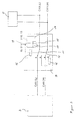
- FIG. 2 shows the principle of the direct detection of the operating state of the Distance and control system 3 shown.
- the CAN bus decoupler 10 has a control unit 14, which via a signal line 13 with the speed and distance control system 3 connected is. Furthermore, the control unit 14 via terminal 15 and Terminal 31 of the motor vehicle supplied with energy. With the help of a between Terminal 31 and the control unit 14 arranged relay 15 switches the control unit 14, the switches 11 and 12 in the bus lines CAN (L) and CAN (H).
- this system 3 sends a rectangular pulse train with constant Frequency on the signal line 13. This signal is from the control unit 14 evaluated. In normal operation, the control unit 14 becomes a correct one Detect signal on signal line 13.
- the CAN bus remains between the control units 3 and 5, i.e. switches 11 and 12 remain in the respective position a.
- the control unit 14 evaluates this as not correct. As a result of this evaluation, the control unit 14 the double relay 15 switched and the system under consideration galvanically from CAN bus separated. The switches 11 and 12 go into position b about.
- the speed and distance control system is 3 arranged at the end of the bus, with a bus terminating resistor in switch position b 16 connected between the CAN (H) and CAN (L) bus lines is. With the help of this resistor 16, a correct bus termination is ensured. For other arrangements of the control unit 3 to be decoupled it is sufficient to connect this control unit to the CAN bus lines (L) and CAN (H).
- FIG. 3 shows an indirect detection of the operating state of the speed and distance control system 3 shown.
- the speed and distance control system 3 with the control unit 14 of the CAN bus decoupler 10 only via the CAN (L) and CAN bus lines (H) connected.
- the control unit 14 of the CAN bus decoupler 10 has a CAN bus interface 17, which is connected via lines 18 and 19 are coupled to the CAN (H) and CAN (L) bus lines.
- a detection the operating state is here from the control unit 14 only by the Evaluation of the bus status via a busoff test known per se carried out at which errors on the bus system registered by counting and when the device reaches a certain counter reading Bus is switched off.
- the control unit 14 controls the double relay 15, so that this in turn the distance and speed control system 3 galvanically from the CAN bus CAN (L) and CAN (H) separates.
- the go from the relay 15 controlled switches 11 and 12 from state a to the state b over, whereby the speed and distance control system 3 is disconnected from the CAN bus.
- a bus terminating resistor 16 provided between the lines CAN (H) and CAN (L) to ensure proper Realize bus termination.
- FIG. 4 shows a combination of the recognition options according to FIG. 2 and 3.
- the distance and control system 3 is via a signal line 13 connected to the control unit 14 of the CAN bus decoupler 10.
- the control unit 14 is connected to the bus lines via lines 18 and 19 CAN (H) and CAN (L) connected.
- CAN bus decoupler 10 is unable to detect one to be able to plausibility check correct signal on the signal line 13. This Plausibility is checked by observing the CAN bus 4th
- CAN bus decoupler 10 To simplify the circuit structure, it is possible to use the CAN bus decoupler 10 to integrate structurally in the engine control unit 5. Depending on requirements it is also possible to connect crash sensors 20 to a bus system, to make a plausibility check through the electronic recognition of the To enable accidents as such.
Landscapes
- Engineering & Computer Science (AREA)
- Transportation (AREA)
- Mechanical Engineering (AREA)
- Small-Scale Networks (AREA)
- Control Of Electric Motors In General (AREA)
Description
- Figur 1:
- Anordnung der Abstandsregeleinrichtung an einem Kraftfahrzeug,
- Figur 2:
- direkte Erkennung eines abzukoppelnden Busteilnehmers,
- Figur 3:
- indirekte Erkennung des abzukoppelnden Busteilnehmers,
- Figur 4:
- Kombination der Erkennung des abzukoppelnden Busteilnehmers nach Figur 2 und 3.
Claims (9)
- Schaltungsanordnung zur Abkopplung einer elektronischen Einrichtung (3) von einer Datenleitung (CAN(H); CAN(L)) in einem Kraftfahrzeug (1), über welche die elektronische Einrichtung (3) und mindestens ein weiteres elektrisches System (5, 6, 7, 8) Informationen austauschen, wobei die elektronische Einrichtung (3) mit einer Fehlererkennungseinrichtung (10) verbunden ist, welche bei Feststellung eines Fehlers der elektronischen Einrichtung (3) diese galvanisch von der Datenleitung (CAN(H); CAN(L)) abkoppelt, wobei die Betriebsfähigkeit des elektronischen Systems (5, 6, 7, 8) voll aufrechterhalten bleibt, dadurch gekennzeichnet, dass die Schaltungsanordnung eine einzige, auf jede Datenleitung (CAN(H); CAN(L)) zugreifende und in dieser angeordnete Schalteinrichtung (11; 12) aufweist, die von der Fehlererkennungseinrichtung (10) bei Erkennung des Fehlers angesteuert wird und die Datenleitungen (CAN(H); CAN(L)) zu der an oder nahe der Außenfläche eines Kraftfahrzeuges angeordneten elektronischen Einrichtung (3) unterbricht.
- Schaltungsanordnung nach Anspruch 1, dadurch gekennzeichnet, dass die Schalteinrichtung (11, 12,) eine Verbindung mit einem Datenleitungsabschlusswiderstand (16) herstellt.
- Schaltungsanordnung nach Anspruch 1 oder 2, dadurch gekennzeichnet, dass die Fehlererkennungseinrichtung (10) die Schalteinrichtung (11, 12) über ein Relais (15) oder einen elektronischen Schalter ansteuert.
- Schaltungsanordnung nach Anspruch 2 oder 3, dadurch gekennzeichnet, dass die elektronische Einrichtung (3) über eine Signalleitung (13) mit der Fehlererkennungseinrichtung (10) verbunden ist.
- Schaltungsanordnung nach Anspruch 2 oder 3, dadurch gekennzeichnet, dass die Fehlererkennungseinrichtung (10) über die Datenleitung (CAN(H); CAN(L)) mit der zu überwachenden elektronischen Einrichtung (3) verbunden ist und in Abhängigkeit der Bewertung des Zustandes der Datenleitung (CAN(H); CAN(L)) die Schalteinrichtung (3) ansteuert.
- Schaltungsanordnung nach einem der vorhergehenden Ansprüche, dadurch gekennzeichnet, dass die Datenleitung (CAN(H); CAN(L)) ein Zweidraht-Bussystem ist, wobei in jeder Busleitung (CAN(H), CAN(L)) ein Schalter (11, 12) angeordnet ist, und die Schalter (11, 12) beider Busleitungen (CAN(H); CAN(L)) gleichzeitig über ein Doppelrelais (15) von der Fehlererkennungseinrichtung (10) gesteuert werden.
- Schaltungsanordnung nach einem der vorhergehenden Ansprüche, dadurch gekennzeichnet, dass die Fehlererkennungseinrichtung (10) Bestandteil des elektronischen Systems (5) ist.
- Schaltungsanordnung nach Anspruch 1, dadurch gekennzeichnet, dass die elektronische Einrichtung (3) ein Steuergerät, insbesondere eine Abstandsregeleinrichtung eines Kraftfahrzeuges ist.
- Schaltungsanordnung nach Anspruch 1, dadurch gekennzeichnet, dass die elektronische Einrichtung (3) eine Sensoreinrichtung des Kraftfahrzeuges ist.
Applications Claiming Priority (2)
| Application Number | Priority Date | Filing Date | Title |
|---|---|---|---|
| DE19833462 | 1998-07-24 | ||
| DE19833462A DE19833462A1 (de) | 1998-07-24 | 1998-07-24 | Schaltungsanordnung zur Abkopplung einer elektronischen Einrichtung von einer Datenleitung in einem Kraftfahrzeug |
Publications (3)
| Publication Number | Publication Date |
|---|---|
| EP0983905A2 EP0983905A2 (de) | 2000-03-08 |
| EP0983905A3 EP0983905A3 (de) | 2000-09-13 |
| EP0983905B1 true EP0983905B1 (de) | 2003-12-17 |
Family
ID=7875263
Family Applications (1)
| Application Number | Title | Priority Date | Filing Date |
|---|---|---|---|
| EP99109570A Expired - Lifetime EP0983905B1 (de) | 1998-07-24 | 1999-05-14 | Schaltungsanordnung zur Abkopplung einer elektronischen Einrichtung von einer Datenleitung in einem Kraftfahrzeug |
Country Status (2)
| Country | Link |
|---|---|
| EP (1) | EP0983905B1 (de) |
| DE (2) | DE19833462A1 (de) |
Cited By (2)
| Publication number | Priority date | Publication date | Assignee | Title |
|---|---|---|---|---|
| CN103158646A (zh) * | 2011-12-16 | 2013-06-19 | 赫拉胡克公司 | 具有薄膜传感器的机动车辆 |
| WO2013127479A1 (en) | 2012-02-27 | 2013-09-06 | Televic Rail Nv | Devices and method for assigning network addresses |
Families Citing this family (18)
| Publication number | Priority date | Publication date | Assignee | Title |
|---|---|---|---|---|
| US6448671B1 (en) * | 1999-08-05 | 2002-09-10 | Trw Inc. | Distributed vehicle safety system having fault protection |
| DE19946993A1 (de) * | 1999-09-30 | 2001-04-19 | Infineon Technologies Ag | Schutzschaltung für ein zugriffsarbitriertes Bussystem-Netzwerk |
| DE19960859A1 (de) * | 1999-12-16 | 2001-07-05 | Trw Automotive Electron & Comp | Entkopplungseinheit für Bussysteme |
| DE10027362A1 (de) * | 2000-06-02 | 2001-12-06 | Bosch Gmbh Robert | Verfahren zum Behandeln von einem fehlerhaften Gerät in einem Fahrzeugkommunikationsnetz |
| DE10030996B4 (de) | 2000-06-30 | 2010-07-22 | Robert Bosch Gmbh | Vorrichtung und Verfahren zur Steuerung von Betriebsabläufen, insbesondere bei einem Fahrzeug |
| DE10059601A1 (de) * | 2000-11-30 | 2002-08-29 | John Deere Fabriek Horst Bv | Bussystem für ein landwirtschaftliches Fahrzeug |
| DE10123802B4 (de) * | 2001-05-16 | 2004-10-14 | Audi Ag | Steuerungssystem für Kfz-Komponenten und Steuerungsverfahren |
| DE10236080A1 (de) * | 2002-08-07 | 2004-02-19 | Robert Bosch Gmbh | Verfahren und Vorrichtung zur Steuerung von Betriebsabläufen, insbesondere in einem Fahrzeug |
| DE10325164B4 (de) * | 2003-05-27 | 2013-12-12 | Volkswagen Ag | Bussystem in einem Kraftfahrzeug |
| DE10324437B4 (de) | 2003-05-28 | 2005-10-20 | Knorr Bremse Systeme | CAN-Bus-System |
| DE10359487A1 (de) * | 2003-12-18 | 2005-07-21 | Bayerische Motoren Werke Ag | Steuergerät mit außer Funktion setzbarer Schnittstelle |
| JP5089693B2 (ja) | 2006-08-02 | 2012-12-05 | オートリブ ディベロップメント エービー | 制御装置および機能制御方法 |
| DE102007059438B4 (de) | 2007-12-10 | 2018-05-30 | Volkswagen Ag | Verfahren zum Übertragen von Daten zwischen Steuervorrichtungen in einem Fahrzeug |
| US8831821B2 (en) | 2010-12-17 | 2014-09-09 | GM Global Technology Operations LLC | Controller area network message transmission disable testing systems and methods |
| DE102011016924A1 (de) * | 2011-04-13 | 2012-10-18 | Leopold Kostal Gmbh & Co. Kg | Sensoranordnung für ein Kraftfahrzeug |
| KR102399493B1 (ko) | 2014-01-23 | 2022-05-19 | 삼성전자주식회사 | 반도체 칩 표면검사 장치 및 이를 이용한 반도체 칩의 표면검사 방법 |
| EP4033714B1 (de) * | 2021-01-25 | 2023-06-14 | ZKW Group GmbH | Verfahren zur datenübertragung zwischen zwei digital steuerbaren fahrzeugkomponenten |
| CN118107600A (zh) * | 2024-01-05 | 2024-05-31 | 中国第一汽车股份有限公司 | Can信号预留字段处理方法、装置、电子设备及存储介质 |
Family Cites Families (7)
| Publication number | Priority date | Publication date | Assignee | Title |
|---|---|---|---|---|
| JPS5484403A (en) * | 1977-12-19 | 1979-07-05 | Hitachi Ltd | Double system transmission line switching system |
| DE3429941C2 (de) * | 1983-08-15 | 1987-04-16 | Honda Giken Kogyo K.K., Tokio/Tokyo | Kommunikationssystem für Fahrzeugkörper |
| DE4340048A1 (de) * | 1993-11-24 | 1995-06-01 | Bosch Gmbh Robert | Vorrichtung zum Austauschen von Daten und Verfahren zum Betreiben der Vorrichtung |
| DE19611942C2 (de) * | 1996-03-26 | 2003-02-20 | Daimler Chrysler Ag | Halbleiterschaltkreis für ein elektronisches Steuergerät |
| DE19749306A1 (de) * | 1996-12-20 | 1998-06-25 | Mannesmann Vdo Ag | Verfahren und Anordnung zur vorausschauenden Bestimmung eines Fahrkorridors eines Kraftfahrzeuges |
| SE9604759L (sv) * | 1996-12-23 | 1998-03-23 | Nob Elektronik Ab | Elektroniskt ringformigt bussystem uppdelad i ett flertal sektioner |
| SE511458C2 (sv) * | 1997-02-17 | 1999-10-04 | Mecel Ab | Skyddsanordning för diagnosuttag i distribuerade datornät |
-
1998
- 1998-07-24 DE DE19833462A patent/DE19833462A1/de not_active Ceased
-
1999
- 1999-05-14 DE DE59908077T patent/DE59908077D1/de not_active Expired - Lifetime
- 1999-05-14 EP EP99109570A patent/EP0983905B1/de not_active Expired - Lifetime
Cited By (2)
| Publication number | Priority date | Publication date | Assignee | Title |
|---|---|---|---|---|
| CN103158646A (zh) * | 2011-12-16 | 2013-06-19 | 赫拉胡克公司 | 具有薄膜传感器的机动车辆 |
| WO2013127479A1 (en) | 2012-02-27 | 2013-09-06 | Televic Rail Nv | Devices and method for assigning network addresses |
Also Published As
| Publication number | Publication date |
|---|---|
| EP0983905A2 (de) | 2000-03-08 |
| EP0983905A3 (de) | 2000-09-13 |
| DE59908077D1 (de) | 2004-01-29 |
| DE19833462A1 (de) | 2000-01-27 |
Similar Documents
| Publication | Publication Date | Title |
|---|---|---|
| EP0983905B1 (de) | Schaltungsanordnung zur Abkopplung einer elektronischen Einrichtung von einer Datenleitung in einem Kraftfahrzeug | |
| DE19913131A1 (de) | Stromversorgungssystem mit zwei Batterien unterschiedlicher Spannung | |
| EP1634729B1 (de) | Steuerung für den Antrieb einer Anhängerkupplung | |
| DE10143454B4 (de) | Einrichtung zur Steuerung eines Fahrzeuges | |
| EP3385934A1 (de) | Vorrichtung für die steuerung eines sicherheitsrelevanten vorganges, verfahren zum testen der funktionsfähigkeit der vorrichtung, sowie kraftfahrzeug mit der vorrichtung | |
| EP2628147B1 (de) | Vorrichtung und verfahren zur signalisierung von funktionsausfällen eines fahrzeugs | |
| EP1109348A2 (de) | Entkopplungseinheit für Bussysteme | |
| DE2701925B2 (de) | Fahrzeugsteuerung mit zwei Bordrechnern | |
| DE102017113664A1 (de) | Versorgungsschaltung für elektronische Komponenten aus mehreren Spannungspotentialen | |
| DE19922408B4 (de) | Bus-System mit bei Störungen automatisch abschaltbaren Teilnetzen | |
| DE4416008B4 (de) | Mit einem Regelsystem ausgerüstetes Fahrzeug | |
| EP0642959B1 (de) | Diebstahlsicherung für ein Kraftfahrzeug | |
| EP0598379A2 (de) | Schaltungsanordnung für eine Blinklichtanlage | |
| DE2824168A1 (de) | Einrichtung zur steuerung von spurgebundenen fahrzeugen im zugverband | |
| DE102007059438B4 (de) | Verfahren zum Übertragen von Daten zwischen Steuervorrichtungen in einem Fahrzeug | |
| EP1219070A1 (de) | Datenbussystem für kraftfahrzeuge mit weckanschluss | |
| EP0813995A2 (de) | Schaltungsanordnung zur Verbindung der Blinklichtanlage eines Fahrzeuganhängers mit der Blinklichtanlage eines Zugfahrzeuges | |
| DE102012013502B3 (de) | Verfahren zum Betreiben eines Sicherheitssystems für einen Kraftwagen und Sicherheitssystem | |
| EP1447287B1 (de) | Wischeranlage für Fahrzeug-Windschutzscheiben | |
| DE10058899B4 (de) | X-by-wire-System und Verfahren zu seinem Betrieb | |
| EP1369322B1 (de) | Verfahren und Vorrichtung zur Datenübertragung in einem Kraftfahrzeug | |
| EP3856614A1 (de) | Steuergerät mit einer zur erkennung einer in einer hardwarekomponente vorliegenden signalminderung ausgebildeten vorwarnfunktion | |
| DE10325164B4 (de) | Bussystem in einem Kraftfahrzeug | |
| DE10209551B4 (de) | Verfahren und Vorrichtung zur Steuerung einer Abzugssperre eines Zündschlüssels eines Kraftfahrzeugs | |
| AT414116B (de) | Verfahren zum überwachen von zählpunkten und zählpunkt für gleisfreimeldeanlagen |
Legal Events
| Date | Code | Title | Description |
|---|---|---|---|
| PUAI | Public reference made under article 153(3) epc to a published international application that has entered the european phase |
Free format text: ORIGINAL CODE: 0009012 |
|
| AK | Designated contracting states |
Kind code of ref document: A2 Designated state(s): DE FR GB |
|
| AX | Request for extension of the european patent |
Free format text: AL;LT;LV;MK;RO;SI |
|
| PUAL | Search report despatched |
Free format text: ORIGINAL CODE: 0009013 |
|
| AK | Designated contracting states |
Kind code of ref document: A3 Designated state(s): AT BE CH CY DE DK ES FI FR GB GR IE IT LI LU MC NL PT SE |
|
| AX | Request for extension of the european patent |
Free format text: AL;LT;LV;MK;RO;SI |
|
| 17P | Request for examination filed |
Effective date: 20000927 |
|
| AKX | Designation fees paid |
Free format text: DE FR GB |
|
| RAP1 | Party data changed (applicant data changed or rights of an application transferred) |
Owner name: SIEMENS AKTIENGESELLSCHAFT |
|
| 17Q | First examination report despatched |
Effective date: 20020718 |
|
| GRAH | Despatch of communication of intention to grant a patent |
Free format text: ORIGINAL CODE: EPIDOS IGRA |
|
| GRAS | Grant fee paid |
Free format text: ORIGINAL CODE: EPIDOSNIGR3 |
|
| GRAA | (expected) grant |
Free format text: ORIGINAL CODE: 0009210 |
|
| AK | Designated contracting states |
Kind code of ref document: B1 Designated state(s): DE FR GB |
|
| REG | Reference to a national code |
Ref country code: GB Ref legal event code: FG4D Free format text: NOT ENGLISH |
|
| REF | Corresponds to: |
Ref document number: 59908077 Country of ref document: DE Date of ref document: 20040129 Kind code of ref document: P |
|
| GBT | Gb: translation of ep patent filed (gb section 77(6)(a)/1977) |
Effective date: 20040225 |
|
| ET | Fr: translation filed | ||
| PLBE | No opposition filed within time limit |
Free format text: ORIGINAL CODE: 0009261 |
|
| STAA | Information on the status of an ep patent application or granted ep patent |
Free format text: STATUS: NO OPPOSITION FILED WITHIN TIME LIMIT |
|
| 26N | No opposition filed |
Effective date: 20040920 |
|
| PGFP | Annual fee paid to national office [announced via postgrant information from national office to epo] |
Ref country code: FR Payment date: 20100611 Year of fee payment: 12 |
|
| PGFP | Annual fee paid to national office [announced via postgrant information from national office to epo] |
Ref country code: DE Payment date: 20100531 Year of fee payment: 12 |
|
| PGFP | Annual fee paid to national office [announced via postgrant information from national office to epo] |
Ref country code: GB Payment date: 20100519 Year of fee payment: 12 |
|
| REG | Reference to a national code |
Ref country code: FR Ref legal event code: TP |
|
| REG | Reference to a national code |
Ref country code: GB Ref legal event code: 732E Free format text: REGISTERED BETWEEN 20110825 AND 20110831 |
|
| REG | Reference to a national code |
Ref country code: DE Ref legal event code: R119 Ref document number: 59908077 Country of ref document: DE |
|
| REG | Reference to a national code |
Ref country code: DE Ref legal event code: R119 Ref document number: 59908077 Country of ref document: DE |
|
| GBPC | Gb: european patent ceased through non-payment of renewal fee |
Effective date: 20110514 |
|
| REG | Reference to a national code |
Ref country code: FR Ref legal event code: ST Effective date: 20120131 |
|
| PG25 | Lapsed in a contracting state [announced via postgrant information from national office to epo] |
Ref country code: FR Free format text: LAPSE BECAUSE OF NON-PAYMENT OF DUE FEES Effective date: 20110531 |
|
| PG25 | Lapsed in a contracting state [announced via postgrant information from national office to epo] |
Ref country code: GB Free format text: LAPSE BECAUSE OF NON-PAYMENT OF DUE FEES Effective date: 20110514 |
|
| PG25 | Lapsed in a contracting state [announced via postgrant information from national office to epo] |
Ref country code: DE Free format text: LAPSE BECAUSE OF NON-PAYMENT OF DUE FEES Effective date: 20111130 |