EP0983908A1 - Tablier, véhicule automobile comportant un tel tablier et procédé de montage d'un faisceau de cables mettant en oeuvre un tel tablier - Google Patents
Tablier, véhicule automobile comportant un tel tablier et procédé de montage d'un faisceau de cables mettant en oeuvre un tel tablier Download PDFInfo
- Publication number
- EP0983908A1 EP0983908A1 EP99117179A EP99117179A EP0983908A1 EP 0983908 A1 EP0983908 A1 EP 0983908A1 EP 99117179 A EP99117179 A EP 99117179A EP 99117179 A EP99117179 A EP 99117179A EP 0983908 A1 EP0983908 A1 EP 0983908A1
- Authority
- EP
- European Patent Office
- Prior art keywords
- cables
- bundle
- apron
- guiding
- opening
- Prior art date
- Legal status (The legal status is an assumption and is not a legal conclusion. Google has not performed a legal analysis and makes no representation as to the accuracy of the status listed.)
- Granted
Links
- 238000000034 method Methods 0.000 title claims abstract description 4
- XLYOFNOQVPJJNP-UHFFFAOYSA-N water Substances O XLYOFNOQVPJJNP-UHFFFAOYSA-N 0.000 claims description 4
- 238000005259 measurement Methods 0.000 claims description 3
- 238000000926 separation method Methods 0.000 claims 1
- 238000003780 insertion Methods 0.000 abstract description 4
- 230000037431 insertion Effects 0.000 abstract description 4
- 238000001746 injection moulding Methods 0.000 abstract 1
- 238000004378 air conditioning Methods 0.000 description 3
- 238000010438 heat treatment Methods 0.000 description 2
- 229910000831 Steel Inorganic materials 0.000 description 1
- 238000004026 adhesive bonding Methods 0.000 description 1
- 238000004891 communication Methods 0.000 description 1
- 238000002347 injection Methods 0.000 description 1
- 239000007924 injection Substances 0.000 description 1
- 238000009413 insulation Methods 0.000 description 1
- 239000013307 optical fiber Substances 0.000 description 1
- 210000000056 organ Anatomy 0.000 description 1
- 230000001681 protective effect Effects 0.000 description 1
- 239000000523 sample Substances 0.000 description 1
- 239000000243 solution Substances 0.000 description 1
- 239000010959 steel Substances 0.000 description 1
- 230000009897 systematic effect Effects 0.000 description 1
- 238000009423 ventilation Methods 0.000 description 1
Images

Classifications
-
- B—PERFORMING OPERATIONS; TRANSPORTING
- B60—VEHICLES IN GENERAL
- B60R—VEHICLES, VEHICLE FITTINGS, OR VEHICLE PARTS, NOT OTHERWISE PROVIDED FOR
- B60R16/00—Electric or fluid circuits specially adapted for vehicles and not otherwise provided for; Arrangement of elements of electric or fluid circuits specially adapted for vehicles and not otherwise provided for
- B60R16/02—Electric or fluid circuits specially adapted for vehicles and not otherwise provided for; Arrangement of elements of electric or fluid circuits specially adapted for vehicles and not otherwise provided for electric constitutive elements
- B60R16/0207—Wire harnesses
-
- B—PERFORMING OPERATIONS; TRANSPORTING
- B60—VEHICLES IN GENERAL
- B60R—VEHICLES, VEHICLE FITTINGS, OR VEHICLE PARTS, NOT OTHERWISE PROVIDED FOR
- B60R16/00—Electric or fluid circuits specially adapted for vehicles and not otherwise provided for; Arrangement of elements of electric or fluid circuits specially adapted for vehicles and not otherwise provided for
- B60R16/02—Electric or fluid circuits specially adapted for vehicles and not otherwise provided for; Arrangement of elements of electric or fluid circuits specially adapted for vehicles and not otherwise provided for electric constitutive elements
- B60R16/0207—Wire harnesses
- B60R16/0215—Protecting, fastening and routing means therefor
Definitions
- Modern motor vehicles are equipped with numerous electrical or electronic devices for measuring and / or control comprising probes and actuators arranged in the engine compartment to be connected to display devices or control levers by a cable harness.
- the opening is provided with a device for cable harness guidance.
- the device for guiding the wiring harness also protects the passenger compartment against water inlets.
- the main object of the present invention is an apron for separating the engine compartment from the passenger compartment of a motor vehicle provided with an air inlet opening in the passenger compartment, characterized in that it comprises means for guiding through this opening of a beam of interconnect cables.
- the invention also relates to an apron characterized in that the opening has a rounded end ensuring the passage of said wiring harness.
- the invention also relates to an apron, characterized in that the cable bundle guiding means ensure the guiding of the bundle of cables along a tangential path to the deck on both sides opposite.
- the invention also relates to an apron, characterized in that the cable bundle guide means have a U-shape.
- the invention also relates to an apron, characterized in what the cable bundle guiding means provide protection against ingress of water into the passenger compartment.
- the invention also relates to an apron, characterized in that the means for guiding the cable bundle have the shape of a gutter overturned.
- the invention also relates to an apron, characterized in what it includes means for holding a coiled part of the bundle cables.
- the invention also relates to an apron, characterized in that the means for holding a wound part of the cable bundle comprises a housing.
- the invention also relates to a motor vehicle characterized in that it comprises such an apron and in that the beam of cables provide interconnection between electrical devices or electronic, measuring and / or control devices arranged in the compartment motor with display means or control means arranged in the passenger compartment.
- the invention also relates to a method of mounting a bundle of cables in a motor vehicle comprising an apron, characterized in that it comprises a step of introduction and fixing on a opening of an assembly formed by means for guiding a beam of cables and means for maintaining in a rolled up condition a part of said bundle of cables followed by a stage of unwinding of the part wound from the cable harness and by a step of connection of the various cables to their measurement or control device.
- FIGS. 1 to 5 the same references have been used for designate the same elements.
- FIG. 1 to 3 we can see an entrance opening 1 of air practiced in an apron 3, typically made of sheet steel, of a motor vehicle.
- the opening example 1 illustrated has a form elongated rectangular, rounded at one end.
- the radius of curvature of this rounding is slightly greater than the radius of a bundle 5 of cables 5.1 to 5.
- the bundle 5 mainly comprises insulated electrical cables, being well understood that other types of cables such as for example optical fibers, coaxial cables or the like can be incorporated into bundle 5.
- the beam 5 is tangent to the deck 3 on its two faces opposite and crosses the opening 1 at its rounded end.
- a device 7 ensures the guidance and the protection of the beam 5 at its crossing of the opening 1 as well as protection against ingress of water into the passenger compartment.
- the piece of protection and guide 7 advantageously has the shape of a gutter overturned, along the path, for example in a U, of the cable, and being disposed at horse in the engine compartment and in the cockpit.
- Exhibit 7 provides the guiding the cable bundle, preferably tangentially to the bulkhead 3, avoids cutting a cable when pulling on harness 5, and prevents the beam 5 is folded over a radius of curvature incompatible with its correct operation.
- the protective part of the guide means 7 is advantageously made of plastic, for example molded by injection. It is fixed to the apron 3 by gluing, force insertion, riveting, screwing, stapling or the like.
- a device according to the present invention formed in an air inlet in the passenger compartment of a heating and / or air conditioning device.
- This device comprises of part, a part 7 for guiding the cable bundle at the level of the passage of the opening 1 in the apron 3 forming said air inlet and, on the other hand, a box 9 integrated or postponed receiving the beam 5 in a condition rolled up, referenced 5 ', when installing the heater or air conditioning on the vehicle. From this position, the beam will be and the desired connections made in a later step of mounting the vehicle.
- the casing 9 for receiving the wound 5 ′ beam can either be deposited later in the course of bundle 5 or serve as air flow guide pipe.
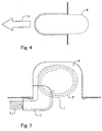
- the housing 9 provided with an element of guide 7 and filled with the bundle 5, 5 ′ is inserted according to arrow 11, by example from the engine compartment to the passenger compartment.
- the shape of the case 9 is on the one hand suitable for receiving the wound bundle and, on the other hand, for shape of opening 1.
- the housing 9 has a flattened and rounded shape.
- the present invention applies mainly to industry automobile.
Landscapes
- Engineering & Computer Science (AREA)
- Mechanical Engineering (AREA)
- Body Structure For Vehicles (AREA)
- Installation Of Indoor Wiring (AREA)
Abstract
Description
- la figure 1 est une vue schématique de face d'une ouverture dans le tablier équipée d'un dispositif selon la présente invention ;
- la figure 2 est une vue de dessus en plan du dispositif de la figure 1 ;
- la figure 3 est une vue selon III-III du dispositif de la figure 1 ;
- la figure 4 est une vue selon IV-IV illustrant l'insertion de la variante de réalisation préférée du dispositif selon la présente invention ;
- la figure 5 est une vue de dessus du dispositif de la figure 4.
Claims (10)
- Tablier de séparation du compartiment moteur de l'habitacle d'un véhicule automobile muni d'une ouverture (1) d'entrée d'air dans l'habitacle, caractérisé en ce qu'il comporte des moyens (7) de guidage à travers cette ouverture (1) d'un faisceau (5) de câbles d'interconnexion (5.1, 5.N).
- Tablier selon la revendication 1, caractérisé en ce que l'ouverture (1) comporte une extrémité arrondie assurant le passage dudit faisceau (5) de câbles (5.1, 5.N).
- Tablier selon l'une quelconque des revendications précédentes, caractérisé en ce que les moyens (7) de guidage du faisceau (5) de câbles (5.1, 5.N) assurent le guidage du faisceau (5) de câbles (5.1, 5.N) selon un chemin tangentiel au tablier (1) sur ses deux faces opposées.
- Tablier selon l'une des revendications précédentes, caractérisé en ce que les moyens de guidage (7) du faisceau (5) de câbles (5.1, 5.N) ont une forme en U.
- Tablier selon l'une quelconque des revendications précédentes, caractérisé en ce que les moyens de guidage (7) du faisceau (5) de câbles (5.1, 5.N) assurent la protection contre des entrées d'eau dans l'habitacle.
- Tablier selon la revendication 5, caractérisé en ce que les moyens (7) de guidage du faisceau (5) de câbles (5.1, 5.N) ont la forme d'une gouttière renversée.
- Tablier selon l'une quelconque des revendications précédentes, caractérisé en ce qu'il comporte des moyens (9) de maintien d'une partie enroulée (5') du faisceau (5) de câbles (5.1, 5.N).
- Tablier selon la revendication 7, caractérisé en ce que les moyens (9) de maintien d'une partie enroulée (5') du faisceau (5) de câbles (5.1,5.N) comporte un boítier.
- Véhicule automobile caractérisé en ce qu'il comporte un tablier (1) selon l'une quelconque des revendications précédentes et en ce que le faisceau (5) de câbles assure l'interconnexion entre des dispositifs électriques ou électroniques, de mesure et/ou de commande disposés dans le compartiment moteur à des moyens d'affichage ou des moyens de commande ou d'alimentation disposés dans l'habitacle.
- Procédé de montage d'un faisceau (5) de câbles (5.1, 5.N) dans un véhicule automobile comportant un tablier (1) selon les revendications 7 ou 8, caractérisé en ce qu'il comporte une étape d'introduction (11) et de fixation sur une ouverture (1) d'un ensemble formé par des moyens (7) de guidage d'un faisceau (5) de câbles (5.1, 5.N) et des moyens (9) de maintien dans une condition enroulée d'une partie (5') dudit faisceau (5) de câbles suivie par une étape de déroulement de la partie enroulée (5') du faisceau (5) de câbles et par une étape de connexion des divers câbles (5.1, 5.N) à leur organe de mesure ou de commande.
Applications Claiming Priority (2)
| Application Number | Priority Date | Filing Date | Title |
|---|---|---|---|
| FR9811032A FR2782967B1 (fr) | 1998-09-03 | 1998-09-03 | Tablier, vehicule automobile comportant un tel tablier et procede de montage d'un faisceau de cables mettant en oeuvre un tel tablier |
| FR9811032 | 1998-09-03 |
Publications (2)
| Publication Number | Publication Date |
|---|---|
| EP0983908A1 true EP0983908A1 (fr) | 2000-03-08 |
| EP0983908B1 EP0983908B1 (fr) | 2004-08-18 |
Family
ID=9530092
Family Applications (1)
| Application Number | Title | Priority Date | Filing Date |
|---|---|---|---|
| EP19990117179 Expired - Lifetime EP0983908B1 (fr) | 1998-09-03 | 1999-09-01 | Tablier, véhicule automobile comportant un tel tablier et procédé de montage d'un faisceau de cables mettant en oeuvre un tel tablier |
Country Status (3)
| Country | Link |
|---|---|
| EP (1) | EP0983908B1 (fr) |
| DE (1) | DE69919467T2 (fr) |
| FR (1) | FR2782967B1 (fr) |
Citations (4)
| Publication number | Priority date | Publication date | Assignee | Title |
|---|---|---|---|---|
| JPS6430856A (en) * | 1987-07-24 | 1989-02-01 | Honda Motor Co Ltd | Wiring structure for vehicle |
| WO1994019213A1 (fr) * | 1993-02-24 | 1994-09-01 | Siemens Aktiengesellschaft | Dispositif de distribution pour composants electriques |
| US5641942A (en) * | 1993-10-04 | 1997-06-24 | Sumitomo Wiring Systems, Ltd. | Waterproof construction of wiring harness |
| US5792995A (en) * | 1994-11-08 | 1998-08-11 | Yazaki Corporation | Wire harness grommet with tubular section and fastener |
-
1998
- 1998-09-03 FR FR9811032A patent/FR2782967B1/fr not_active Expired - Fee Related
-
1999
- 1999-09-01 EP EP19990117179 patent/EP0983908B1/fr not_active Expired - Lifetime
- 1999-09-01 DE DE69919467T patent/DE69919467T2/de not_active Expired - Fee Related
Patent Citations (4)
| Publication number | Priority date | Publication date | Assignee | Title |
|---|---|---|---|---|
| JPS6430856A (en) * | 1987-07-24 | 1989-02-01 | Honda Motor Co Ltd | Wiring structure for vehicle |
| WO1994019213A1 (fr) * | 1993-02-24 | 1994-09-01 | Siemens Aktiengesellschaft | Dispositif de distribution pour composants electriques |
| US5641942A (en) * | 1993-10-04 | 1997-06-24 | Sumitomo Wiring Systems, Ltd. | Waterproof construction of wiring harness |
| US5792995A (en) * | 1994-11-08 | 1998-08-11 | Yazaki Corporation | Wire harness grommet with tubular section and fastener |
Non-Patent Citations (1)
| Title |
|---|
| PATENT ABSTRACTS OF JAPAN vol. 013, no. 206 (M - 826) 16 May 1989 (1989-05-16) * |
Also Published As
| Publication number | Publication date |
|---|---|
| FR2782967B1 (fr) | 2000-10-20 |
| FR2782967A1 (fr) | 2000-03-10 |
| DE69919467D1 (de) | 2004-09-23 |
| DE69919467T2 (de) | 2005-09-15 |
| EP0983908B1 (fr) | 2004-08-18 |
Similar Documents
| Publication | Publication Date | Title |
|---|---|---|
| EP2075887A1 (fr) | Pince ondulée | |
| FR2569911A1 (fr) | Guide-cables etanche a l'humidite | |
| FR3005803A1 (fr) | Boite de jonction electrique | |
| EP1236599A1 (fr) | Système de montage d'un faisceau de cables pour portière | |
| JP2002281650A (ja) | ハーネス弛み吸収構造 | |
| JP2015071333A (ja) | ドア用ワイヤーハーネスモジュール | |
| WO2024100335A1 (fr) | Vehicule electrique avec groupe motopropulseur dispose a l'avant alimente par des cables haute tension | |
| CN208101886U (zh) | 一种用于汽车的线束保护壳 | |
| EP0983908B1 (fr) | Tablier, véhicule automobile comportant un tel tablier et procédé de montage d'un faisceau de cables mettant en oeuvre un tel tablier | |
| EP2949557B1 (fr) | Véhicule à moteur de type à selle | |
| JP5569115B2 (ja) | ワイヤハーネス | |
| US7237820B2 (en) | Module for equipping a motor vehicle rear opening panel | |
| JP4064641B2 (ja) | クリップ及びクリップの取付構造 | |
| JP4201523B2 (ja) | ケーブルの複合クランプおよびクランプ方法 | |
| US20230311763A1 (en) | Rear View Mirror Arrangement for a Motorcycle | |
| EP1220767B1 (fr) | Dispositif de fixation de faisceau de cables dans une planche de bord | |
| FR2824670A3 (fr) | Dispositif de fixation d'un faisceau de cables | |
| JP2022067341A (ja) | ドア用配線モジュール及び複合サービスホールカバー | |
| JP7456456B2 (ja) | インストルメントパネル | |
| JP3009024B2 (ja) | 分岐ワイヤーハーネスの支持構造 | |
| JP2553056Y2 (ja) | 自動車のインストルメントパネル | |
| KR200165890Y1 (ko) | 자동차 와이어 장착용 클립 | |
| KR960005401Y1 (ko) | 자동차의 전동식 미러 콘넥터 고정구조 | |
| KR0173616B1 (ko) | 끈고정용 브라켓트 | |
| FR3069825A1 (fr) | Goulotte de faisceau planche de bord avec casquette anti ruissellement. |
Legal Events
| Date | Code | Title | Description |
|---|---|---|---|
| PUAI | Public reference made under article 153(3) epc to a published international application that has entered the european phase |
Free format text: ORIGINAL CODE: 0009012 |
|
| AK | Designated contracting states |
Kind code of ref document: A1 Designated state(s): DE ES GB IT |
|
| AX | Request for extension of the european patent |
Free format text: AL;LT;LV;MK;RO;SI |
|
| 17P | Request for examination filed |
Effective date: 20000830 |
|
| AKX | Designation fees paid |
Free format text: DE ES GB IT |
|
| RAP1 | Party data changed (applicant data changed or rights of an application transferred) |
Owner name: VALEO ELECTRONIQUE |
|
| 17Q | First examination report despatched |
Effective date: 20020607 |
|
| GRAP | Despatch of communication of intention to grant a patent |
Free format text: ORIGINAL CODE: EPIDOSNIGR1 |
|
| RAP1 | Party data changed (applicant data changed or rights of an application transferred) |
Owner name: VISTEON SYSTEMES INTERIEURS S.A.S. Owner name: VALEO ELECTRONIQUE |
|
| GRAS | Grant fee paid |
Free format text: ORIGINAL CODE: EPIDOSNIGR3 |
|
| GRAA | (expected) grant |
Free format text: ORIGINAL CODE: 0009210 |
|
| AK | Designated contracting states |
Kind code of ref document: B1 Designated state(s): DE ES GB IT |
|
| PG25 | Lapsed in a contracting state [announced via postgrant information from national office to epo] |
Ref country code: IT Free format text: LAPSE BECAUSE OF FAILURE TO SUBMIT A TRANSLATION OF THE DESCRIPTION OR TO PAY THE FEE WITHIN THE PRESCRIBED TIME-LIMIT;WARNING: LAPSES OF ITALIAN PATENTS WITH EFFECTIVE DATE BEFORE 2007 MAY HAVE OCCURRED AT ANY TIME BEFORE 2007. THE CORRECT EFFECTIVE DATE MAY BE DIFFERENT FROM THE ONE RECORDED. Effective date: 20040818 Ref country code: GB Free format text: LAPSE BECAUSE OF FAILURE TO SUBMIT A TRANSLATION OF THE DESCRIPTION OR TO PAY THE FEE WITHIN THE PRESCRIBED TIME-LIMIT Effective date: 20040818 |
|
| REG | Reference to a national code |
Ref country code: GB Ref legal event code: FG4D Free format text: NOT ENGLISH |
|
| REF | Corresponds to: |
Ref document number: 69919467 Country of ref document: DE Date of ref document: 20040923 Kind code of ref document: P |
|
| PG25 | Lapsed in a contracting state [announced via postgrant information from national office to epo] |
Ref country code: ES Free format text: LAPSE BECAUSE OF FAILURE TO SUBMIT A TRANSLATION OF THE DESCRIPTION OR TO PAY THE FEE WITHIN THE PRESCRIBED TIME-LIMIT Effective date: 20041129 |
|
| GBV | Gb: ep patent (uk) treated as always having been void in accordance with gb section 77(7)/1977 [no translation filed] |
Effective date: 20040818 |
|
| PLBE | No opposition filed within time limit |
Free format text: ORIGINAL CODE: 0009261 |
|
| STAA | Information on the status of an ep patent application or granted ep patent |
Free format text: STATUS: NO OPPOSITION FILED WITHIN TIME LIMIT |
|
| 26N | No opposition filed |
Effective date: 20050519 |
|
| PGFP | Annual fee paid to national office [announced via postgrant information from national office to epo] |
Ref country code: DE Payment date: 20060907 Year of fee payment: 8 |
|
| PG25 | Lapsed in a contracting state [announced via postgrant information from national office to epo] |
Ref country code: DE Free format text: LAPSE BECAUSE OF NON-PAYMENT OF DUE FEES Effective date: 20080401 |