EP0984120A1 - Verbindungsanordnung - Google Patents
Verbindungsanordnung Download PDFInfo
- Publication number
- EP0984120A1 EP0984120A1 EP99116578A EP99116578A EP0984120A1 EP 0984120 A1 EP0984120 A1 EP 0984120A1 EP 99116578 A EP99116578 A EP 99116578A EP 99116578 A EP99116578 A EP 99116578A EP 0984120 A1 EP0984120 A1 EP 0984120A1
- Authority
- EP
- European Patent Office
- Prior art keywords
- plastic
- cap
- connecting part
- base body
- metal base
- Prior art date
- Legal status (The legal status is an assumption and is not a legal conclusion. Google has not performed a legal analysis and makes no representation as to the accuracy of the status listed.)
- Granted
Links
- 239000004033 plastic Substances 0.000 claims abstract description 124
- 229920003023 plastic Polymers 0.000 claims abstract description 124
- 239000002184 metal Substances 0.000 claims description 87
- 239000004952 Polyamide Substances 0.000 claims description 3
- 229920002647 polyamide Polymers 0.000 claims description 3
- 230000015572 biosynthetic process Effects 0.000 abstract description 2
- 238000000034 method Methods 0.000 description 11
- 230000000694 effects Effects 0.000 description 4
- 229920002292 Nylon 6 Polymers 0.000 description 3
- 238000010521 absorption reaction Methods 0.000 description 2
- 230000007613 environmental effect Effects 0.000 description 1
- 230000002093 peripheral effect Effects 0.000 description 1
Images



Classifications
-
- E—FIXED CONSTRUCTIONS
- E05—LOCKS; KEYS; WINDOW OR DOOR FITTINGS; SAFES
- E05B—LOCKS; ACCESSORIES THEREFOR; HANDCUFFS
- E05B15/00—Other details of locks; Parts for engagement by bolts of fastening devices
- E05B15/02—Striking-plates; Keepers; Bolt staples; Escutcheons
Definitions
- the invention relates to a connection arrangement with a metal base body and a cap for covering the metal base body.
- connection arrangements are used in building fittings as well as in the sanitary area.
- the metal base body can have a mounting surface, for example a door, to be connected there as Basis for further superstructures or attachments or as a functional element serve.
- the cap To connect the cap to the metal body the cap usually has several locking projections in undercuts engage the metal body.
- the plastic cap is formed (plastic cap), and that the connection arrangement has a plastic connecting part on the metal base body is attachable and on which the plastic cap to form a Plastic-plastic contact can be locked.
- a plastic connecting part is therefore provided, with which can also be connected to the plastic cap.
- Possible deformations caused by environmental influences thus have an effect of plastics, especially expansions of polyamides, in in essentially the same way on both the cap and the Connection part from, so that the stability of this connection even in If the plastics used are susceptible to deformation does not deteriorate significantly in the long run.
- the plastic connecting part can be a Functional element act when using the connection arrangement fulfills other tasks as building hardware or as a sanitary element.
- the cap and the connecting part can have locking projections and corresponding undercuts be provided on the cap and the connecting part.
- the undercut on the plastic connecting part or on the Plastic cap designed as a spring-back undercut. This ensures the stability of the connection between the cap and the connecting part increased even further because, on the one hand, a higher original engagement pressure between the locking projection and the spring undercut can be provided, and because the spring travel of the spring undercut Deformation of the plastic cap and the plastic connecting part to compensate for each other to an even greater extent can
- the spring undercut can be used as an undercut on a longitudinal extension be formed by the plastic connecting part or of the plastic cap across, especially at right angles to that direction extends along which the locking projection into the undercut formed should grip (direction of engagement). It is preferred if the The longitudinal direction of this longitudinal process is also transverse, in particular extends perpendicular to the direction along which the plastic cap to cover the base body including the connecting part to be placed on the plastic connector (direction of attachment). In this way, the one that forms the spring undercut Longitudinal process within the main extension plane of the connecting part run so that the plastic connecting part with a shallow depth and can be manufactured in a particularly simple manner.
- the design of the undercut can also be that of the snap connection provided between the plastic cap and the plastic connecting part Snap projection be designed to be resilient.
- plastics with different relative to each other Deformation susceptibility can be used. In doing so, extent and direction of the expected deformation are taken into account. Inexpensive plastics can be used at least in part, for which a comparatively high susceptibility to deformation is accepted can be.
- the plastic connecting part and the plastic cap can be the connecting part for immediate snap connection with the cap between the cap and be arranged the base body, or the base body is between the connecting part and the cap arranged, at least the undercuts or locking projections of the connecting part protrude the base body to the snap connection with the cap enable.
- the object of the invention is for a connection arrangement of the entry mentioned type to the other solved in that the cap Metal is formed (metal cap) that the connection arrangement Has plastic connecting part that can be attached to the metal base body and at least one resilient undercut (Spring undercut), and that the metal cap at least has a locking projection assigned to the spring undercut, through which the metal cap with the plastic connector can be locked.
- the cap Metal is formed (metal cap) that the connection arrangement Has plastic connecting part that can be attached to the metal base body and at least one resilient undercut (Spring undercut), and that the metal cap at least has a locking projection assigned to the spring undercut, through which the metal cap with the plastic connector can be locked.
- a metal cap is therefore provided is not directly connected to the metal base body, but with a connecting part fastened to the metal base body Plastic, for example made of a polyamide, is locked.
- the plastic connecting part has one or more spring undercuts, and the metal cap has corresponding locking projections.
- the undercut formed can also be the one formed from metal Cap with the arrangement of metal body and plastic connecting part be snapped to cover this arrangement. Any subsequent deformation of the plastic connector can by the springback effect of the spring undercut be compensated for, so that a reliable seat of the Metal cap is guaranteed.
- the features of the embodiment with a plastic cap transferable accordingly are the features of the embodiment with a plastic cap transferable accordingly.
- the spring undercut on a cross to the direction of engagement and / or Longitudinal extension of the plastic connecting part in the direction of attachment be formed, and the connecting part can with respect to the metal cap be arranged in front of or behind the metal body.
- the above designations of the viewing directions refer to on the arrangement of the parts of the connection arrangement shown in the assembled state shown in Fig. 4 on a mounting surface.
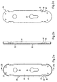
- FIG. 1a-1c show a plastic connecting part 11 of a connecting arrangement, the as a fitting on a door to hold a door handle as well as a locking cylinder.
- the plastic connector 11 has four recessed locking areas 15 with rectangular recesses on a rear side 13 17. At each rest area 15 there is one Rectangular recess 17 integrally formed longitudinal extension 19. The outside of each longitudinal extension 19 extends parallel to the corresponding narrow side of the plastic connecting part 11 A front 21 of the plastic connecting part 11 is each longitudinal extension 19 bevelled towards its outside.
- the plastic connector 11 also has a pusher opening 23, a Lock opening 25 and four fastening openings 27.
- FIGS. 2a-2c show an assigned to the plastic connecting part 11 Metal base body 29. This has four rectangular recesses 31, a handle opening 33, a lock opening 35 and four fastening openings 37, the location and extent of the recesses 17th or openings 23, 25, 27 of the plastic connecting part 11 correspond.
- the metal base body 29 has a rear 39 Fold 41.
- the fold 41 is interrupted at the rectangular recesses 31, and there are at right angles to the metal body 29 locking tabs 43.
- the locking tabs 43 are with respect to the fold 41 set back and have one at each of their two longitudinal ends Detent tooth 45.
- 3a to 3c show an associated cap 47.
- This has a circumferential one Edge area 49, which is perpendicular to the main direction of extension the cap 47 and on the inside - according to the arrangement of the longitudinal extensions 19 on the plastic connecting part 11 - four latching projections 51 with a nose-shaped cross section are arranged (see also Fig. 4).
- the cap 47 has one of the pusher openings 23, 33 and lock openings 25, 35 of the plastic connecting part 11 or the metal base body 29 corresponding pusher opening 53 and Lock opening 55 on.
- the assembly of the plastic connecting part 11, the metal base body 29 and the cap 47 is carried out in the following way: First, for the purpose of pre-assembly, the plastic connecting part 11 on the Metal base body 29 fastened by the plastic connecting part 11 with its front 21 in the fold 41 on the back 39 of the metal base body 29 is used.
- the latching tabs 43 engage behind with their locking teeth 45, the rectangular recesses 17 on their transverse edges.
- the plastic connecting part 11 and the metal base body 29 also via the fastening openings 27, 37 or other fastening openings as well as corresponding fastening elements be attached to each other.
- the metal base body 29 can be attached in this way be attached to a door that the fold 41 with its narrow side on the Door abuts and the plastic connecting part 11 between the door, the Metal base body 29 and the fold 41 is caught.
- the basic body 29 can, for example, via the fastening openings 37 with the door be screwed.
- the cap 47 can be opened the metal base body 29 or from the rectangular recesses 31 of the metal base body 29 protruding longitudinal extensions 19 of the Plastic connector 11 are placed. Thereby lie first the locking projections 51 of the cap 47 on the bevels of the longitudinal processes 19 on. With further touchdown movement the longitudinal processes 19 pushed back into the respective rectangular recess 17, and the Locking projections 51 can be made along the outside of the longitudinal extensions 19 up to the level of the locking areas 15 on the rear 13 of the plastic connecting part 11 slide. There snap-in projections 51 snap on the likewise recessed rear side 13 of the longitudinal processes 19.
- the longitudinal extensions 19 thus form undercuts for the locking projections 51 of the cap 47, the longitudinal extensions 19 with respect to the direction of engagement, in which the locking projections 51 ultimately the longitudinal extensions 19 cover, are designed to spring back.
- the rectangular recesses 17 on the plastic connecting part 11 are therefore not only used for receiving the locking tabs 43 of the metal base body 29, but also as Spring back area for the longitudinal processes 19.
- the deepened formation of the Latching areas 15, in particular the longitudinal extensions 19, enable a snapping in the locking projections 51 of the cap 47 also in such cases where the plastic connector 11 on the mounting surface in question is present.
- Fig. 4 shows the so attached to a mounting surface 57 Connection arrangement in a cross section along the planes IV-IV, which are shown in Fig. 1c for the plastic connecting part 11 and accordingly chosen for the metal base body 29 and the cap 47 are. 4, the cap 47 is in one Setting direction 59 on the metal base body 29 together with the plastic connecting part 11 placed, and engage behind the locking projections 51 the longitudinal extensions 19 each in an engagement direction 61.
- the internal dimensions of the on the mounting surface 57 adjacent fold 41 of the metal base body 29 slightly larger are selected as the dimensions of the outline of the plastic connecting part 11. Stand only at the rectangular recesses 31 the longitudinal extensions 19 of the plastic connecting part serving as spring undercuts 11 over the fold 41 of the metal base body 29 about.
- the internal dimensions of the edge region 49 of the cap 47 correspond to the External dimensions of the longitudinal extensions 19 in their relaxed state.
- the Depth of the cap edge region 49 is selected so that when on the metal base body 29 adjacent cap 47 whose edge region 49 on the fastening surface 57 rests and the locking projections 51 secure the longitudinal extensions 19 reach behind.
- the fold 41 and the locking tab 43 of the metal base body 29 and the rear 13 of the plastic connecting part 11 are also on the mounting surface 57.
- the cap 47 can - like the plastic connecting part - made of plastic be made.
- the locking projections 51 of the cap 47 to an increasing extent out of engagement with the longitudinal processes 19 reach if the cap 47 is due to moisture absorption extends along the sectional plane shown in Fig. 4.
- this will Effect compensated by the fact that the plastic connecting part 11 with its longitudinal extensions 19 is made of plastic and, if necessary expands in the appropriate directions.
- the cap 47 can also be made of metal.
- the cap 47 In this Fall can be the resilient configuration of the 19 formed by the longitudinal processes Undercuts for making the snap connection required inherent elasticity of the locking projections 51 of the metal cap 47 compensate. Expansion due to moisture absorption of the plastic connecting part 11 is transferred to the longitudinal processes 19 and reinforces the locking connection received with the locking projections 51.
- the locking connection between the locking tabs 43 of the metal base body 29 and the rectangular recesses 17 of the plastic connecting part 11, on the other hand, is not critical to a possible deformation of the plastic connecting part 11, since this latching connection is simply loved the pre-assembly of plastic connector 11 and metal base 29 serves together.
- FIGS. 5a to 5c and 6a and 6b An alternative possibility for this locking connection is in FIGS. 5a to 5c and 6a and 6b for a further metal base body 29 'and a another plastic connecting part 11 'shown.
- the further metal base body 29 ' has a circumferential fold 41 Rectangular recesses 31 (see FIG. 5b). Adjacent to each rectangular recess 31 protrudes from the inner peripheral surface of the fold 41 Latch 65 in the direction of the longitudinal center axis of the further metal base body 29 '.
- the further metal base body 29 ' is attached attached to the further plastic connecting part 11 'by such the plastic connecting part 11 'is placed, which the locking lugs 65th engage behind the locking undercuts 63 or the locking undercuts 63 spring back to the catches 65.
- the plastic connecting part 11 out of less to produce plastic that is susceptible to deformation, e.g. from PA12, while a comparatively for the production of the cap 47 made of plastic inexpensive plastic, for example PA6, can be selected can.
Landscapes
- Connection Of Plates (AREA)
- Building Environments (AREA)
- Coupling Device And Connection With Printed Circuit (AREA)
- Monitoring And Testing Of Exchanges (AREA)
- Manufacturing Of Electric Cables (AREA)
- Non-Disconnectible Joints And Screw-Threaded Joints (AREA)
- Road Paving Structures (AREA)
- Steam Or Hot-Water Central Heating Systems (AREA)
- Residential Or Office Buildings (AREA)
Abstract
Description
- Fig. 1a - 1c
- eine Rückansicht bzw. eine Seitenansicht bzw. eine Vorderansicht eines Kunststoff-Verbindungsteils,
- Fig. 2a - 2c
- eine Rückansicht bzw. eine Seiten-Querschnittsansicht entlang der Ebene IIb-IIb bzw. eine Vorderansicht eines Metall-Grundkörpers,
- Fig. 3a - 3c
- eine Rückansicht bzw. eine Seiten-Querschnittsansicht entlang der Ebene IIIb-IIIb bzw. eine Vorderansicht einer Kappe,
- Fig. 4
- eine Querschnittsansicht entlang der Ebenen IV-IV des Kunststoff-Verbindungsteils, des Metall-Grundkörpers und der Kunststoff-Kappe gemäß der Fig. 1a bis 3c im Zustand der gegenseitigen Verbindung und Montage an einer Befestigungsfläche,
- Fig. 5a
- eine Rückansicht einer alternativen Ausführungsform eines Metall-Grundkörpers,
- Fig. 5b
- eine Schnittansicht des Metall-Grundkörpers nach Fig. 5a entlang der Schnittlinie Vb-Vb in Fig. 5a,
- Fig. 5c
- eine Schnittansicht des Metall-Grundkörpers nach Fig. 5a entlang der Schnittlinie Vc-Vc in Fig. 5a,
- Fig. 6a
- eine Draufsicht auf eine alternative Ausführungsform eines mit dem Metall-Grundkörper nach den Fig. 5a bis 5c zu verwendenden Kunststoff-Verbindungsteils, und
- Fig. 6b
- eine Schnittansicht des Kunststoff-Verbindungsteils nach Fig. 6a entlang der Schnittlinie VIb-VIb in Fig. 6a.
- 11
- Kunststoff-Verbindungsteil
- 13
- Rückseite
- 15
- Rastbereich
- 17
- Rechteckausnehmung
- 19
- Längsfortsatz
- 21
- Vorderseite
- 23
- Drückeröffnung
- 25
- Schloßöffnung
- 27
- Befestigungsöffnung
- 29
- Metall-Grundkörper
- 31
- Rechteckausnehmung
- 33
- Drückeröffnung
- 35
- Schloßöffnung
- 37
- Befestigungsöffnung
- 39
- Rückseite
- 41
- Falz
- 43
- Rastlasche
- 45
- Rastzahn
- 47
- Kappe
- 49
- Randbereich
- 51
- Rastvorsprung
- 53
- Drückeröffnung
- 55
- Schloßöffnung
- 57
- Befestigungsfläche
- 59
- Aufsetzrichtung
- 61
- Eingriffsrichtung
Claims (16)
- Verbindungsanordnung mit einem Metall-Grundkörper (29) und einer Kappe (47) zur Bedeckung des Metall-Grundkörpers (29),
dadurch gekennzeichnet,daß die Kappe (47) aus Kunststoff gebildet ist (Kunststoff-Kappe), unddaß die Verbindungsanordnung ein Kunststoff-Verbindungsteil (11) aufweist, das an dem Metall-Grundkörper (29) befestigbar ist und an dem die Kunststoff-Kappe (47) unter Ausbildung eines Kunststoff-Kunststoff-Kontakts verrastbar ist. - Verbindungsanordnung nach Anspruch 1,
dadurch gekennzeichnet,daß zur Verrastung der Kunststoff-Kappe (47) an dem Kunststoff-Verbindungsteil (11) die Kunststoff-Kappe (47) und das Kunststoff-Verbindungsteil (11) wenigstens einen Rastvorsprung (51) bzw. eine Hinterschneidung (19) aufweisen, oder umgekehrt. - Verbindungsanordnung nach Anspruch 2,
dadurch gekennzeichnet,daß die Hinterschneidung (19) rückfedernd ausgestaltet ist (Federhinterschneidung). - Verbindungsanordnung nach Anspruch 3,
dadurch gekennzeichnet,daß die Hinterschneidung (19) zur rückfedernden Ausgestaltung an einem Längsfortsatz (19) ausgebildet ist, dessen Längsrichtung sich quer zu einer Eingriffsrichtung erstreckt, entlang deren der Rastvorsprung (51) in die Hinterschneidung (19) greift. - Verbindungsanordnung nach Anspruch 4,
dadurch gekennzeichnet,daß die Längsrichtung des Längsfortsatzes (19) sich quer zu einer Aufsetzrichtung erstreckt, entlang deren die Kunststoff-Kappe (47) auf das Kunststoff-Verbindungsteil (11) zur gegenseitigen Verrastung aufsetzbar ist. - Verbindungsanordnung nach Anspruch 4 oder 5,
dadurch gekennzeichnet,daß der Längsfortsatz (19) an dem Kunststoff-Verbindungsteil (11) bzw. an der Kunststoff-Kappe (47) angeformt ist. - Verbindungsanordnung nach einem der Ansprüche 4 bis 6,
dadurch gekennzeichnet,daß der Längsfortsatz (19) in entspanntem Zustand entlang seiner Längsrichtung von dem Kunststoff-Verbindungsteil (11) bzw. von der Kunststoff-Kappe (47) freistehend beabstandet angeordnet ist. - Verbindungsanordnung nach einem der vorhergehenden Ansprüche,
dadurch gekennzeichnet,daß die Kunststoff-Kappe (47) und das Kunststoff-Verbindungsteil (11) jeweils aus einem relativ zueinander stärker bzw. weniger verformungsanfälligen Kunststoff gebildet sind, insbesondere aus PA6 bzw. PA12. - Verbindungsanordnung nach einem der vorhergehenden Ansprüche,
dadurch gekennzeichnet,daß der Metall-Grundkörper (29) zur Anordnung zwischen dem Kunststoff-Verbindungsteil (11) und der Kunststoff-Kappe (47) vorgesehen ist. - Verbindungsanordnung nach Anspruch 9,
dadurch gekennzeichnet,daß das Kunststoff-Verbindungsteil (11) zur Anordnung zwischen dem Metall-Grundkörper (29) und einer Befestigungsfläche (57), insbesondere einer Tür, vorgesehen ist. - Verbindungsanordnung nach einem der Ansprüche 1 bis 8,
dadurch gekennzeichnet,daß das Kunststoff-Verbindungsteil (11) als ein Einlegeteil zur Anordnung zwischen dem Metall-Grundkörper (29) und der Kunststoff-Kappe (47) vorgesehen ist. - Verbindungsanordnung nach einem der vorhergehenden Ansprüche,
dadurch gekennzeichnet,daß das Kunststoff-Verbindungsteil (11)an dem Metall-Grundkörper (29) befestigbar ist.durch eine Rastverbindung und/oderdurch eine Schraubverbindung und/oderdurch ein Einklemmen zwischen dem Metall-Grundkörper (29) und einer Tür (57) - Verbindungsanordnung nach Anspruch 12,
dadurch gekennzeichnet,daß zur Herstellung der Rastverbindung zwischen dem Kunststoff-Verbindungsteil (11) und dem Metall-Grundkörper (29) das Kunststoff-Verbindungsteil (11) wenigstens eine Eintrittsöffnung (17) aufweist und der Metall-Grundkörper (29) wenigstens eine Rastlasche (43) mit wenigstens einem in einer Längsrichtung der Rastlasche (43) hervorstehenden Rastzahn (45) aufweist, wobei die Erstreckung der Rastlasche (43) in der Längsrichtung ungefähr so groß ist wie die entsprechende Erstreckung der Eintrittsöffnung (17). - Verbindungsanordnung nach Anspruch 12,
dadurch gekennzeichnet,daß zur Herstellung der Rastverbindung zwischen dem Kunststoff-Verbindungsteil (11) und dem Metall-Grundkörper (29) der Metall-Grundkörper (29) wenigstens eine Rastnase (65) aufweist, die an einer Innenseitenfläche eines von dem Metall-Grundkörper (29) abgewinkelten Falzes (41) angeordnet ist, und das Kunststoff-Verbindungsteil (11) an einer äußeren Begrenzungsfläche eine Rast-hinterschneidung (63) aufweist, die in ihrer Form und Anordnung der Rastnase (65) entspricht, wobei die Rastnase (65) und/oder die Rasthinterschneidung (63) rückfedernd ausgebildet sind. - Verbindungsanordnung mit einem Metall-Grundkörper (29) und einer Kappe (47) zur Bedeckung des Metall-Grundkörpers (29),
dadurch gekennzeichnet,daß die Kappe (47) aus Metall gebildet ist (Metall-Kappe),daß die Verbindungsanordnung ein Kunststoff-Verbindungsteil (11) aufweist, das an dem Metall-Grundkörper befestigbar ist und wenigstens eine rückfedernd ausgebildete Hinterschneidung (19) (Federhinterschneidung) aufweist, unddaß die Metall-Kappe (47) wenigstens einen der Federhinterschneidung (19) zugeordneten Rastvorsprung (51) aufweist, durch den die Metall-Kappe (47) mit dem Kunststoff-Verbindungsteil (11) verrastbar ist. - Verbindungsanordnung nach einem der vorhergehenden Ansprüche,
dadurch gekennzeichnet,daß es sich bei dem Kunststoff um ein Polyamid handelt.
Applications Claiming Priority (2)
| Application Number | Priority Date | Filing Date | Title |
|---|---|---|---|
| DE19839813A DE19839813A1 (de) | 1998-09-01 | 1998-09-01 | Verbindungsanordnung |
| DE19839813 | 1998-09-01 |
Publications (2)
| Publication Number | Publication Date |
|---|---|
| EP0984120A1 true EP0984120A1 (de) | 2000-03-08 |
| EP0984120B1 EP0984120B1 (de) | 2003-10-29 |
Family
ID=7879433
Family Applications (1)
| Application Number | Title | Priority Date | Filing Date |
|---|---|---|---|
| EP99116578A Expired - Lifetime EP0984120B1 (de) | 1998-09-01 | 1999-08-24 | Verbindungsanordnung |
Country Status (5)
| Country | Link |
|---|---|
| EP (1) | EP0984120B1 (de) |
| AT (1) | ATE253163T1 (de) |
| DE (2) | DE19839813A1 (de) |
| DK (1) | DK0984120T3 (de) |
| ES (1) | ES2205657T3 (de) |
Cited By (1)
| Publication number | Priority date | Publication date | Assignee | Title |
|---|---|---|---|---|
| EP3179016A1 (de) * | 2015-12-08 | 2017-06-14 | Abloy Oy | Abdeckplattenanordnung |
Families Citing this family (3)
| Publication number | Priority date | Publication date | Assignee | Title |
|---|---|---|---|---|
| DE202006013094U1 (de) * | 2006-08-25 | 2007-06-14 | Hafi Beschläge GmbH | Abdeckrosette für Schließzylinder |
| DE102010026218A1 (de) * | 2010-07-06 | 2012-01-12 | Gm Global Technology Operations Llc (N.D.Ges.D. Staates Delaware) | Befestigungsmittel |
| IT201600073512A1 (it) * | 2016-07-14 | 2018-01-14 | Bonaiti Serrature Spa | Dispositivo di riscontro senza viti per serrature |
Citations (8)
| Publication number | Priority date | Publication date | Assignee | Title |
|---|---|---|---|---|
| US1479659A (en) * | 1922-10-30 | 1924-01-01 | Yale & Towne Mfg Co | Facing-ring structure for cylinder locks |
| US2423206A (en) * | 1943-07-05 | 1947-07-01 | Schlage Lock Co | Escutcheon plate fastener |
| GB2168420A (en) * | 1984-12-13 | 1986-06-18 | Marston & Company Limited Albe | Door handle escutcheons |
| DE3521151A1 (de) * | 1985-06-13 | 1987-01-02 | Melchert Fa Franz Karl | Tuerbeschlag mit innenschild und aussenschild |
| US5088781A (en) * | 1990-01-10 | 1992-02-18 | Nissan Motor Co., Ltd. | Handle structure |
| DE9413608U1 (de) * | 1994-08-24 | 1994-12-08 | Franz Schneider Brakel Gmbh & Co, 33034 Brakel | Beschlag für Türen und Fenster |
| DE29503138U1 (de) * | 1995-02-24 | 1995-04-20 | Hoppe AG, 35260 Stadtallendorf | Rosetten-Befestigung |
| DE4420037A1 (de) * | 1994-06-08 | 1995-12-14 | Wilke Heinrich Hewi Gmbh | Vorrichtung zur Befestigung eines Verbindungselements in einer Aufnahmeöffnung eines Bauteils und dafür geeigneter Vierkantstift |
Family Cites Families (4)
| Publication number | Priority date | Publication date | Assignee | Title |
|---|---|---|---|---|
| DE7524748U (de) * | 1975-12-11 | Preh J Elektrofeinmechanische Werke | Lösbare Rastvorrichtung | |
| DE2814656C3 (de) * | 1978-04-05 | 1980-11-13 | Daimler-Benz Ag, 7000 Stuttgart | Befestigung eines Verkleidungsteiles an Blechbauteilen |
| DE3330221A1 (de) * | 1983-08-22 | 1985-03-07 | Gerhard 7107 Neckarsulm Kaminski | Verbindungselement |
| DE3414845A1 (de) * | 1984-04-19 | 1985-06-20 | Daimler-Benz Ag, 7000 Stuttgart | Loesbare befestigung eines bauteils an einem plattenfoermigen tragteil |
-
1998
- 1998-09-01 DE DE19839813A patent/DE19839813A1/de not_active Withdrawn
-
1999
- 1999-08-24 ES ES99116578T patent/ES2205657T3/es not_active Expired - Lifetime
- 1999-08-24 DE DE59907524T patent/DE59907524D1/de not_active Expired - Fee Related
- 1999-08-24 DK DK99116578T patent/DK0984120T3/da active
- 1999-08-24 AT AT99116578T patent/ATE253163T1/de not_active IP Right Cessation
- 1999-08-24 EP EP99116578A patent/EP0984120B1/de not_active Expired - Lifetime
Patent Citations (8)
| Publication number | Priority date | Publication date | Assignee | Title |
|---|---|---|---|---|
| US1479659A (en) * | 1922-10-30 | 1924-01-01 | Yale & Towne Mfg Co | Facing-ring structure for cylinder locks |
| US2423206A (en) * | 1943-07-05 | 1947-07-01 | Schlage Lock Co | Escutcheon plate fastener |
| GB2168420A (en) * | 1984-12-13 | 1986-06-18 | Marston & Company Limited Albe | Door handle escutcheons |
| DE3521151A1 (de) * | 1985-06-13 | 1987-01-02 | Melchert Fa Franz Karl | Tuerbeschlag mit innenschild und aussenschild |
| US5088781A (en) * | 1990-01-10 | 1992-02-18 | Nissan Motor Co., Ltd. | Handle structure |
| DE4420037A1 (de) * | 1994-06-08 | 1995-12-14 | Wilke Heinrich Hewi Gmbh | Vorrichtung zur Befestigung eines Verbindungselements in einer Aufnahmeöffnung eines Bauteils und dafür geeigneter Vierkantstift |
| DE9413608U1 (de) * | 1994-08-24 | 1994-12-08 | Franz Schneider Brakel Gmbh & Co, 33034 Brakel | Beschlag für Türen und Fenster |
| DE29503138U1 (de) * | 1995-02-24 | 1995-04-20 | Hoppe AG, 35260 Stadtallendorf | Rosetten-Befestigung |
Cited By (1)
| Publication number | Priority date | Publication date | Assignee | Title |
|---|---|---|---|---|
| EP3179016A1 (de) * | 2015-12-08 | 2017-06-14 | Abloy Oy | Abdeckplattenanordnung |
Also Published As
| Publication number | Publication date |
|---|---|
| EP0984120B1 (de) | 2003-10-29 |
| DE19839813A1 (de) | 2000-06-08 |
| ES2205657T3 (es) | 2004-05-01 |
| ATE253163T1 (de) | 2003-11-15 |
| DE59907524D1 (de) | 2003-12-04 |
| DK0984120T3 (da) | 2004-03-08 |
Similar Documents
| Publication | Publication Date | Title |
|---|---|---|
| DE10159380B4 (de) | Verbindungsmutter zum Anschrauben von Konstruktionselementen an einem plattenartigen Bauteil | |
| DE10349449B3 (de) | Befestigungselement zur Verbindung eines Bauteils mit einem Trägerbauteil | |
| DE60304318T2 (de) | Befestigung einer rohrklemme | |
| DE102017108320B4 (de) | Flachteilhalter für die Befestigung eines Flachteils an einem Rahmengestell eines Schaltschranks und ein entsprechender Schaltschrank | |
| DE202008011760U1 (de) | Vorrichtung zur Befestigung einer Strebe an einem Radschützer | |
| DE102017108335A1 (de) | Befestigungsanordnung und ein entsprechendes Schaltschrankgehäuse | |
| EP0675295A1 (de) | Befestigungsvorrichtung | |
| DE60114107T2 (de) | Verstellungsplatte für das Schliessblech eines Fahrzeugschlosses | |
| DE60125748T2 (de) | Türgriff für ein Kraftfahrzeug | |
| EP0984120B1 (de) | Verbindungsanordnung | |
| EP1004711B1 (de) | Abdeck-Rosette | |
| EP1687164A1 (de) | Aggregateträger mit integrierter schlossbefestigung für eine kraftfahrzeugtür | |
| DE1914116A1 (de) | Durch Zusammenstecken und Einrasten montierbares Kameragehaeuse | |
| DE102016120650A1 (de) | Ringförmige Steckkupplung und Verfahren zur Herstellung einer Verbindung zwischen Bauteilen mithilfe der ringförmigen Steckkupplung | |
| EP1597451A1 (de) | Vorreiberverschluss | |
| DE102018209343B3 (de) | Kraftfahrzeug | |
| EP1230490B1 (de) | Befestigungselement zum lösbaren verbinden von rechtwinklig zueinander angeordneten blechplatten | |
| DE29920379U1 (de) | Steckkupplung | |
| DE19847270B4 (de) | Stoßstangenbefestigungskonstruktion | |
| DE10208505B4 (de) | Verbindungselement, Anordnung aus Verkleidungsteil mit Verbindungselement und Dichtungsprofil und Verfahren zur Montage | |
| DE10252879A1 (de) | Befestigungsvorrichtung, insbesondere zur Befestigung eines Kühlmoduls an einem Fahrzeugrahmen | |
| DE19706560A1 (de) | Ringschloß zum Sichern von beweglichen Gegenständen, insbesondere Zweirädern oder dergleichen Fahrzeuge | |
| DE10159475B4 (de) | Fahrgestell eines Nutzfahrzeugs | |
| DE20213314U1 (de) | Drehgriff zur Betätigung eines Schlosses einer Tür oder eines Fensters | |
| DE102016200568B4 (de) | Mehrteiliges Gehäuse aus Kunststoff |
Legal Events
| Date | Code | Title | Description |
|---|---|---|---|
| PUAI | Public reference made under article 153(3) epc to a published international application that has entered the european phase |
Free format text: ORIGINAL CODE: 0009012 |
|
| AK | Designated contracting states |
Kind code of ref document: A1 Designated state(s): AT BE CH DE DK ES FR GB IT LI LU NL SE |
|
| AX | Request for extension of the european patent |
Free format text: AL;LT;LV;MK;RO;SI |
|
| 17P | Request for examination filed |
Effective date: 20000403 |
|
| 17Q | First examination report despatched |
Effective date: 20000602 |
|
| AKX | Designation fees paid |
Free format text: AT BE CH DE DK ES FR GB IT LI LU NL SE |
|
| GRAH | Despatch of communication of intention to grant a patent |
Free format text: ORIGINAL CODE: EPIDOS IGRA |
|
| GRAS | Grant fee paid |
Free format text: ORIGINAL CODE: EPIDOSNIGR3 |
|
| GRAA | (expected) grant |
Free format text: ORIGINAL CODE: 0009210 |
|
| AK | Designated contracting states |
Kind code of ref document: B1 Designated state(s): AT BE CH DE DK ES FR GB IT LI LU NL SE |
|
| REG | Reference to a national code |
Ref country code: GB Ref legal event code: FG4D Free format text: NOT ENGLISH |
|
| REG | Reference to a national code |
Ref country code: CH Ref legal event code: EP |
|
| REG | Reference to a national code |
Ref country code: SE Ref legal event code: TRGR |
|
| REF | Corresponds to: |
Ref document number: 59907524 Country of ref document: DE Date of ref document: 20031204 Kind code of ref document: P |
|
| GBT | Gb: translation of ep patent filed (gb section 77(6)(a)/1977) |
Effective date: 20040118 |
|
| REG | Reference to a national code |
Ref country code: DK Ref legal event code: T3 |
|
| REG | Reference to a national code |
Ref country code: ES Ref legal event code: FG2A Ref document number: 2205657 Country of ref document: ES Kind code of ref document: T3 |
|
| ET | Fr: translation filed | ||
| PGFP | Annual fee paid to national office [announced via postgrant information from national office to epo] |
Ref country code: LU Payment date: 20040824 Year of fee payment: 6 |
|
| PGFP | Annual fee paid to national office [announced via postgrant information from national office to epo] |
Ref country code: SE Payment date: 20040825 Year of fee payment: 6 Ref country code: DK Payment date: 20040825 Year of fee payment: 6 |
|
| PGFP | Annual fee paid to national office [announced via postgrant information from national office to epo] |
Ref country code: ES Payment date: 20040826 Year of fee payment: 6 |
|
| PLBE | No opposition filed within time limit |
Free format text: ORIGINAL CODE: 0009261 |
|
| STAA | Information on the status of an ep patent application or granted ep patent |
Free format text: STATUS: NO OPPOSITION FILED WITHIN TIME LIMIT |
|
| 26N | No opposition filed |
Effective date: 20040730 |
|
| PG25 | Lapsed in a contracting state [announced via postgrant information from national office to epo] |
Ref country code: LU Free format text: LAPSE BECAUSE OF NON-PAYMENT OF DUE FEES Effective date: 20050824 |
|
| PG25 | Lapsed in a contracting state [announced via postgrant information from national office to epo] |
Ref country code: SE Free format text: LAPSE BECAUSE OF NON-PAYMENT OF DUE FEES Effective date: 20050825 Ref country code: ES Free format text: LAPSE BECAUSE OF NON-PAYMENT OF DUE FEES Effective date: 20050825 |
|
| PG25 | Lapsed in a contracting state [announced via postgrant information from national office to epo] |
Ref country code: DK Free format text: LAPSE BECAUSE OF NON-PAYMENT OF DUE FEES Effective date: 20050831 |
|
| REG | Reference to a national code |
Ref country code: DK Ref legal event code: EBP |
|
| EUG | Se: european patent has lapsed | ||
| REG | Reference to a national code |
Ref country code: ES Ref legal event code: FD2A Effective date: 20050825 |
|
| PGFP | Annual fee paid to national office [announced via postgrant information from national office to epo] |
Ref country code: NL Payment date: 20080813 Year of fee payment: 10 Ref country code: CH Payment date: 20080814 Year of fee payment: 10 |
|
| PGFP | Annual fee paid to national office [announced via postgrant information from national office to epo] |
Ref country code: IT Payment date: 20080823 Year of fee payment: 10 Ref country code: FR Payment date: 20080813 Year of fee payment: 10 Ref country code: AT Payment date: 20080814 Year of fee payment: 10 |
|
| PGFP | Annual fee paid to national office [announced via postgrant information from national office to epo] |
Ref country code: GB Payment date: 20080821 Year of fee payment: 10 |
|
| PGFP | Annual fee paid to national office [announced via postgrant information from national office to epo] |
Ref country code: DE Payment date: 20081030 Year of fee payment: 10 |
|
| PGFP | Annual fee paid to national office [announced via postgrant information from national office to epo] |
Ref country code: BE Payment date: 20080918 Year of fee payment: 10 |
|
| BERE | Be: lapsed |
Owner name: HEINRICH WILKE G.M.B.H. *HEWI Effective date: 20090831 |
|
| REG | Reference to a national code |
Ref country code: NL Ref legal event code: V1 Effective date: 20100301 Ref country code: CH Ref legal event code: PL |
|
| GBPC | Gb: european patent ceased through non-payment of renewal fee |
Effective date: 20090824 |
|
| PG25 | Lapsed in a contracting state [announced via postgrant information from national office to epo] |
Ref country code: LI Free format text: LAPSE BECAUSE OF NON-PAYMENT OF DUE FEES Effective date: 20090831 Ref country code: CH Free format text: LAPSE BECAUSE OF NON-PAYMENT OF DUE FEES Effective date: 20090831 |
|
| REG | Reference to a national code |
Ref country code: FR Ref legal event code: ST Effective date: 20100430 |
|
| PG25 | Lapsed in a contracting state [announced via postgrant information from national office to epo] |
Ref country code: BE Free format text: LAPSE BECAUSE OF NON-PAYMENT OF DUE FEES Effective date: 20090831 Ref country code: AT Free format text: LAPSE BECAUSE OF NON-PAYMENT OF DUE FEES Effective date: 20090824 |
|
| PG25 | Lapsed in a contracting state [announced via postgrant information from national office to epo] |
Ref country code: NL Free format text: LAPSE BECAUSE OF NON-PAYMENT OF DUE FEES Effective date: 20100301 Ref country code: FR Free format text: LAPSE BECAUSE OF NON-PAYMENT OF DUE FEES Effective date: 20090831 Ref country code: DE Free format text: LAPSE BECAUSE OF NON-PAYMENT OF DUE FEES Effective date: 20100302 |
|
| PG25 | Lapsed in a contracting state [announced via postgrant information from national office to epo] |
Ref country code: GB Free format text: LAPSE BECAUSE OF NON-PAYMENT OF DUE FEES Effective date: 20090824 |
|
| PG25 | Lapsed in a contracting state [announced via postgrant information from national office to epo] |
Ref country code: IT Free format text: LAPSE BECAUSE OF NON-PAYMENT OF DUE FEES Effective date: 20090824 |