EP0984143A2 - Improvements to rotary pumps - Google Patents
Improvements to rotary pumps Download PDFInfo
- Publication number
- EP0984143A2 EP0984143A2 EP99306909A EP99306909A EP0984143A2 EP 0984143 A2 EP0984143 A2 EP 0984143A2 EP 99306909 A EP99306909 A EP 99306909A EP 99306909 A EP99306909 A EP 99306909A EP 0984143 A2 EP0984143 A2 EP 0984143A2
- Authority
- EP
- European Patent Office
- Prior art keywords
- pump
- impeller
- cavity
- engine
- coolant
- Prior art date
- Legal status (The legal status is an assumption and is not a legal conclusion. Google has not performed a legal analysis and makes no representation as to the accuracy of the status listed.)
- Withdrawn
Links
Images


Classifications
-
- F—MECHANICAL ENGINEERING; LIGHTING; HEATING; WEAPONS; BLASTING
- F04—POSITIVE - DISPLACEMENT MACHINES FOR LIQUIDS; PUMPS FOR LIQUIDS OR ELASTIC FLUIDS
- F04D—NON-POSITIVE-DISPLACEMENT PUMPS
- F04D29/00—Details, component parts, or accessories
- F04D29/04—Shafts or bearings, or assemblies thereof
- F04D29/046—Bearings
- F04D29/047—Bearings hydrostatic; hydrodynamic
-
- F—MECHANICAL ENGINEERING; LIGHTING; HEATING; WEAPONS; BLASTING
- F04—POSITIVE - DISPLACEMENT MACHINES FOR LIQUIDS; PUMPS FOR LIQUIDS OR ELASTIC FLUIDS
- F04C—ROTARY-PISTON, OR OSCILLATING-PISTON, POSITIVE-DISPLACEMENT MACHINES FOR LIQUIDS; ROTARY-PISTON, OR OSCILLATING-PISTON, POSITIVE-DISPLACEMENT PUMPS
- F04C18/00—Rotary-piston pumps specially adapted for elastic fluids
- F04C18/02—Rotary-piston pumps specially adapted for elastic fluids of arcuate-engagement type, i.e. with circular translatory movement of co-operating members, each member having the same number of teeth or tooth-equivalents
-
- F—MECHANICAL ENGINEERING; LIGHTING; HEATING; WEAPONS; BLASTING
- F01—MACHINES OR ENGINES IN GENERAL; ENGINE PLANTS IN GENERAL; STEAM ENGINES
- F01P—COOLING OF MACHINES OR ENGINES IN GENERAL; COOLING OF INTERNAL-COMBUSTION ENGINES
- F01P5/00—Pumping cooling-air or liquid coolants
- F01P5/10—Pumping liquid coolant; Arrangements of coolant pumps
-
- F—MECHANICAL ENGINEERING; LIGHTING; HEATING; WEAPONS; BLASTING
- F04—POSITIVE - DISPLACEMENT MACHINES FOR LIQUIDS; PUMPS FOR LIQUIDS OR ELASTIC FLUIDS
- F04D—NON-POSITIVE-DISPLACEMENT PUMPS
- F04D13/00—Pumping installations or systems
- F04D13/02—Units comprising pumps and their driving means
- F04D13/021—Units comprising pumps and their driving means containing a coupling
- F04D13/024—Units comprising pumps and their driving means containing a coupling a magnetic coupling
- F04D13/027—Details of the magnetic circuit
-
- F—MECHANICAL ENGINEERING; LIGHTING; HEATING; WEAPONS; BLASTING
- F04—POSITIVE - DISPLACEMENT MACHINES FOR LIQUIDS; PUMPS FOR LIQUIDS OR ELASTIC FLUIDS
- F04D—NON-POSITIVE-DISPLACEMENT PUMPS
- F04D29/00—Details, component parts, or accessories
- F04D29/04—Shafts or bearings, or assemblies thereof
- F04D29/041—Axial thrust balancing
- F04D29/0413—Axial thrust balancing hydrostatic; hydrodynamic thrust bearings
-
- F—MECHANICAL ENGINEERING; LIGHTING; HEATING; WEAPONS; BLASTING
- F04—POSITIVE - DISPLACEMENT MACHINES FOR LIQUIDS; PUMPS FOR LIQUIDS OR ELASTIC FLUIDS
- F04D—NON-POSITIVE-DISPLACEMENT PUMPS
- F04D5/00—Pumps with circumferential or transverse flow
- F04D5/002—Regenerative pumps
Definitions
- This invention relates to coolant pumps for internal combustion engines.
- An object of the invention is therefore to mitigate or overcome at least some of these problems.
- a coolant pump for an I.C. engine comprises a pump cavity housing an impeller rotatable about an axis, the impeller axis being located coaxially with the rotational axis of the crankshaft of the engine.
- Such a location simplifies drive which may be either direct or geared to the crankshaft without requiring the conventional belt drive as is necessary when the pump axis is parallel to the crankshaft but at a remote location.
- crankshaft mounted drive pulley for a belt drive system, and drive the coolant pump from that pulley (but not from that belt).
- the pump is driven by magnetic coupling using a first set of driving magnets in a face of the pulley and a second set of driven magnets, or torque ring, in the corresponding and adjacent impeller face, with a containment shell located between the two sets.
- the purpose of the shell is to contain the coolant within the pump but permit magnetic flux to couple two sets.
- the crankshaft location reduces power requirement because of the more efficient coolant flow paths possible from what is essentially a low level location relative to the cooled areas of the engine. Power consumption may be reduced because of reduced cavitation in such a location.
- the pump can be a regenerative or peripheral type, or a centrifugal type.
- a coolant pump for an I.C. engine is characterised by the use of a regenerative impeller located in a peripherally discontinuous pump cavity.
- the impeller may comprise a disc formed with radial flutes extending to its periphery and on both faces of the disc, which fluted marginal zone lies in the pump cavity.
- the cavity formed between two co-operating components of the pump body provides a substantial clearance about the fluted marginal zone only around the major portion of the impeller disc, typically 330° or thereabouts, but provides a suitable running clearance over the face areas of the disc radially inwardly of the fluted marginal zone and over the remaining 30° or thereabouts of the marginal zone.
- the cavity connects to inlet and outlet ports at opposite ends of the substantial clearance portion, that is to say at opposite sides of the minimum clearance portion at the periphery.
- Such a regenerative impeller system may give a pump head which is substantially higher than available with a conventional centrifugal action coolant pump having central inlet and tangential discharge thus obviating the need to rotate the impeller at a speed significantly greater than the crankshaft speed.
- a magnetic coupling driven regenerative impeller coolant pump has a balance port extending between a generally peripherally extending pumping cavity and the radially inward zone within the pump to encourage pressurised flow of coolant through the pump as lubricant for bearings journalling the pump impeller.
- a further aspect of the invention provides a coolant pump for an I.C. engine comprising a pump body housing a cavity and an impeller within the cavity, wherein part of the body is formed by the timing case cover adjacent the crankshaft.
- the pump body is in part integral with the timing case cover.
- Another aspect of the invention provides a pump for an internal combustion engine having a magnetically driven impeller, which impeller is rotatable peripherally about the crankshaft of the engine.
- the invention also provides that any one of the features of the invention described above or in the following description, may be combined with any other feature, and/or aspect of the invention.
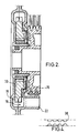
- the pump body comprises first component 10 which may be a portion of a timing case mounted on the front end of the engine block and surrounding the crankshaft.
- the centre-line or rotational axis of the crankshaft is indicated by the line 12.
- the pump body is completed by a second component or cover 14 which extends over an annular zone towards the outer periphery of the part 10 but not over the zone closer to the axis 12.
- the parts 10, 14 are, preferably, sealed permanently together along the mating faces indicated by the arrow 16 and define a pumping chamber or cavity 18 therebetween which extends over a substantial portion of the circumference of the parts 10, 14.
- cavity 18 is indicated in part by the broken lines extending in an arc up to and terminating at port 20 which is formed in a stub tube 22 as also shown in Figure 3.
- a similar port 24 in a second stub tube 26 is located at the opposite end (clockwise from the first end in this example) of the pump cavity 18.
- the area between the two ports 20, 24 is not provided with a cavity 18 but is closed off by a web 19 apertured to provide only a close clearance around the periphery of the impeller.
- the impeller comprises a generally disc-like part 30, see Figure 3, provided with a complete ring of regularly pitched flutes 32 on each of its faces at the outer marginal zone of the disc.
- the impeller has a small clearance 34 between one face and the adjacent inside face of the pump body part 10, a small clearance 36 between the opposite face of the disc and the adjacent face of the second body part 14 and again a small clearance 38 between the rim of the disc and the web portion 19 which separates the two ports.
- the impeller is carried on a hub sleeve 40 associated with journal bearing 42 and carries a series of equispaced driven magnet elements 44 in the face adjacent the drive pulley which is described next.
- the drive pulley 46 is shown engaged with a pair of V belts 48 for the purpose of driving further engine auxiliaries and has a hub 50 in driving association with the crankshaft and located radially inwardly of the pump body part 10. An oil seal 52 is located therebetween.
- the pulley carries driving magnets 54 which are suitably located to transmit driving torque to driven magnets 44 for example at the same radial location from the axis 12 as the driven magnets 44.
- the pump further comprises containment shell 60 which in the illustrated embodiment has a tubular portion 62 trapped between a journal bearing 42 and a corresponding portion of the pump body at 64.
- the shell 60 extends generally radially of axis 12 to contain the thrust bearing 72 and thereafter be appropriately positioned between magnets 44 and 54.
- the shell 60 essentially extends generally radially of the axis 12 between the opposed magnets 44, 54 and is, in this instance, engaged and retained by the pump body part 14 in the area of the reference numeral 66.
- a further bearing, acting as a thrust bearing indicated by the reference numeral 72 is axially trapped between the containment shell 60 and the journal bearing 42.
- the containment shell 60 may be held in place axially by a thrust washer 74 which may possibly be a Circlip (RTM) or equivalent.
- a balance port 70 is provided extending generally radially between the main pump cavity 18 and interior of the pump. The angular location of this in the present embodiment is seen in Figure 1, close to the port 20.
- port 20 is the lower pressure inlet port and higher pressure, near the outlet port 24, causes coolant to leak internally, via clearance 34, through to the bearings 40, 42, and 72, and into a balance chamber 75.
- Flow of coolant, in this instance acting as lubricant, back through to cavity 18 in the vicinity of lower pressure port 20 is mainly through balance port 70 but also through the clearance 36.
- the described pump differs from the conventional coolant pump in its location, that is at crankshaft level instead of being at the top of the engine. It also differs in its type being a regenerative pump rather than a centrifugal pump. It further differs in being driven by the magnetic coupling action, and again in having a pressurised coolant flow about and through the bearing faces inside the pump.
- the invention resides in any one of these features, in any combination of them, or in the constructional details which make the feature(s) possible.
- the thrust bearing 72 is located between the part 10 and the journal bearing 42. Further, it is possible to locate the port 70 by way of a channel formed in the part 10 instead of a channel formed in the part 14.
- the impeller may be a centrifugal type, rather than regenerative or peripheral type, preferably with a hub diameter greater than the largest diameter of the containment shell 66.
Landscapes
- Engineering & Computer Science (AREA)
- Mechanical Engineering (AREA)
- General Engineering & Computer Science (AREA)
- Physics & Mathematics (AREA)
- Fluid Mechanics (AREA)
- Chemical & Material Sciences (AREA)
- Combustion & Propulsion (AREA)
- Structures Of Non-Positive Displacement Pumps (AREA)
Abstract
Description
Claims (15)
- A coolant pump for an I.C. engine comprises a pump cavity housing an impeller rotatable about an axis, the impeller axis being located coaxially with the rotational axis of the crankshaft of the engine.
- A pump according to Claim 1 housing a crankshaft mounted drive pulley for a belt drive system, to drive the coolant pump from that pulley (but preferably not directly that belt).
- A pump according to Claims 1 or 2 wherein the pump is driven by magnetic coupling using a first set of driving magnets in a face of the pulley and a second set of driven magnets, or torque ring, in the corresponding and adjacent impeller face, with a containment shell located between the two sets.
- A pump according to any preceding claim wherein the pump cavity is peripherally discontinuous and the impeller is a regenerative type.
- A coolant pump for an I.C. engine is characterised by a regenerative impeller located in a peripherally discontinuous pump cavity.
- A pump according to Claim 4 or 5 wherein the impeller comprises a disc formed with radial flutes extending to its periphery and on both faces of the disc, which fluted marginal zone lies in the pump cavity.
- A pump according to Claims 4, 5 or 6 wherein the cavity formed between two co-operating components of the pump body provides a substantial clearance about the fluted marginal zone only around the major portion of the impeller disc, preferably 330° or thereabouts.
- A pump according to Claim 7 wherein the cavity provides a suitable running clearance over the face areas of the disc radially inwardly of the fluted marginal zone and preferably over the remaining 30° or thereabouts of the marginal zone.
- A pump according to any of Claims 4 to 8 wherein the cavity connects to inlet and outlet ports substantially at opposite ends of the substantial clearance portion, that is to say at opposite sides of the minimum clearance portion at the periphery.
- A pump according to any preceding claim comprising a balance port extending between a generally peripherally extending pumping cavity and the radially inward zone within the pump to encourage pressurised flow of coolant through the pump as lubricant for bearings journalling the pump impeller.
- A magnetic coupling driven regenerative impeller coolant pump has a balance port extending between a generally peripherally extending pumping cavity and the radially inward zone within the pump to encourage pressurised flow of coolant through the pump as lubricant for bearings journalling the pump impeller.
- A pump according to any preceding claim comprising a pump body housing a cavity and an impeller within the cavity, wherein part of the body is formed by the timing case cover adjacent the crankshaft.
- A coolant pump for an I.C. engine comprising a pump body housing a cavity and an impeller within the cavity, wherein part of the body is formed by the timing case cover adjacent the crankshaft.
- A pump according to any preceding claim having a magnetically driven impeller, which impeller is rotatable peripherally about the crankshaft of the engine.
- A pump for an internal combustion engine having a magnetically driven impeller, which impeller is rotatable peripherally about the crankshaft of the engine.
Applications Claiming Priority (2)
| Application Number | Priority Date | Filing Date | Title |
|---|---|---|---|
| GB9819261 | 1998-09-03 | ||
| GBGB9819261.0A GB9819261D0 (en) | 1998-09-03 | 1998-09-03 | Improvements to rotary pumps |
Publications (2)
| Publication Number | Publication Date |
|---|---|
| EP0984143A2 true EP0984143A2 (en) | 2000-03-08 |
| EP0984143A3 EP0984143A3 (en) | 2001-01-10 |
Family
ID=10838315
Family Applications (1)
| Application Number | Title | Priority Date | Filing Date |
|---|---|---|---|
| EP99306909A Withdrawn EP0984143A3 (en) | 1998-09-03 | 1999-08-31 | Improvements to rotary pumps |
Country Status (12)
| Country | Link |
|---|---|
| EP (1) | EP0984143A3 (en) |
| JP (1) | JP2000080919A (en) |
| KR (1) | KR20000022854A (en) |
| CN (1) | CN1246580A (en) |
| AU (1) | AU4484899A (en) |
| BR (1) | BR9904041A (en) |
| CA (1) | CA2281342A1 (en) |
| GB (2) | GB9819261D0 (en) |
| ID (1) | ID25731A (en) |
| NO (1) | NO994269L (en) |
| TW (1) | TW429285B (en) |
| ZA (1) | ZA995664B (en) |
Cited By (3)
| Publication number | Priority date | Publication date | Assignee | Title |
|---|---|---|---|---|
| WO2006058607A1 (en) * | 2004-12-04 | 2006-06-08 | Brinkmann Pumpen | Pump for liquids under positive pressure |
| WO2008019815A1 (en) * | 2006-08-17 | 2008-02-21 | Busch Produktions Gmbh | Rotor cooling for dry-running twin-shaft vacuum pumps or compressors |
| WO2021121798A1 (en) * | 2019-12-18 | 2021-06-24 | Robert Bosch Gmbh | Side channel compressor for a fuel cell system for conveying and/or compressing a gas |
Families Citing this family (3)
| Publication number | Priority date | Publication date | Assignee | Title |
|---|---|---|---|---|
| RU2315896C1 (en) * | 2006-06-14 | 2008-01-27 | Юлия Алексеевна Щепочкина | Device for pressure transportation of gas or liquid |
| DE102011015784A1 (en) * | 2010-08-12 | 2012-02-16 | Ziehl-Abegg Ag | fan |
| CN110513306B (en) * | 2019-08-02 | 2022-06-03 | 烟台东德氢能技术有限公司 | Hydrogen circulating pump with function opens ice |
Family Cites Families (15)
| Publication number | Priority date | Publication date | Assignee | Title |
|---|---|---|---|---|
| GB856616A (en) * | 1956-03-12 | 1960-12-21 | Ferguson Res Ltd Harry | Improvements in internal combustion engines |
| US3720372A (en) * | 1971-12-09 | 1973-03-13 | Gen Motors Corp | Means for rapidly heating interior of a motor vehicle |
| IT1164933B (en) * | 1979-02-08 | 1987-04-15 | Aspera Spa | MOTOPOMPA |
| JPS5885393A (en) * | 1981-11-13 | 1983-05-21 | Hitachi Ltd | Vertical pump bearing lubrication device |
| DE3534507C2 (en) * | 1984-10-17 | 1986-10-16 | AVL Gesellschaft für Verbrennungskraftmaschinen und Messtechnik mbH, Prof. Dr.Dr.h.c. Hans List, Graz | Internal combustion engine |
| JPS62197624A (en) * | 1986-02-26 | 1987-09-01 | Honda Motor Co Ltd | Water pump device in water cooling type internal combustion engine |
| IT1224053B (en) * | 1988-12-30 | 1990-09-26 | Fiat Auto Spa | INTERNAL COMBUSTION ENGINE PARTICULARLY FOR VEHICLES |
| JPH07111146B2 (en) * | 1989-02-08 | 1995-11-29 | 日産自動車株式会社 | Chain cover device for internal combustion engine |
| US5082428A (en) * | 1990-08-16 | 1992-01-21 | Oklejas Robert A | Centrifugal pump |
| DE4106497A1 (en) * | 1991-03-01 | 1992-09-03 | Gerhard O Wirges | POWER GENERATOR |
| JP3039697B2 (en) * | 1991-03-08 | 2000-05-08 | 富士重工業株式会社 | Water pump mounting structure and water pump driving method for small water-cooled engine |
| RU2083853C1 (en) * | 1993-03-26 | 1997-07-10 | Акционерное общество открытого типа "Ирбитский мотоциклетный завод" | Pump for liquid cooling system of engine |
| DE4404791C1 (en) * | 1994-02-08 | 1995-03-30 | Mannesmann Ag | Structural unit comprising an internal combustion engine and an electrical generator |
| DE19641451A1 (en) * | 1996-10-08 | 1997-03-20 | Voith Turbo Kg | Liquid-cooled automotive power unit with gearbox |
| DE19641450B4 (en) * | 1996-10-08 | 2007-08-02 | Voith Turbo Gmbh & Co. Kg | Drive unit, in particular for a motor vehicle |
-
1998
- 1998-09-03 GB GBGB9819261.0A patent/GB9819261D0/en not_active Ceased
-
1999
- 1999-08-30 AU AU44848/99A patent/AU4484899A/en not_active Abandoned
- 1999-08-31 GB GB9920361A patent/GB2341205A/en not_active Withdrawn
- 1999-08-31 EP EP99306909A patent/EP0984143A3/en not_active Withdrawn
- 1999-09-02 ZA ZA9905664A patent/ZA995664B/en unknown
- 1999-09-02 KR KR1019990037038A patent/KR20000022854A/en not_active Withdrawn
- 1999-09-02 JP JP11249167A patent/JP2000080919A/en active Pending
- 1999-09-02 NO NO994269A patent/NO994269L/en not_active Application Discontinuation
- 1999-09-02 BR BR9904041-7A patent/BR9904041A/en not_active Application Discontinuation
- 1999-09-02 CA CA002281342A patent/CA2281342A1/en not_active Abandoned
- 1999-09-02 TW TW088115107A patent/TW429285B/en active
- 1999-09-03 ID IDP990840A patent/ID25731A/en unknown
- 1999-09-03 CN CN99118395A patent/CN1246580A/en active Pending
Cited By (3)
| Publication number | Priority date | Publication date | Assignee | Title |
|---|---|---|---|---|
| WO2006058607A1 (en) * | 2004-12-04 | 2006-06-08 | Brinkmann Pumpen | Pump for liquids under positive pressure |
| WO2008019815A1 (en) * | 2006-08-17 | 2008-02-21 | Busch Produktions Gmbh | Rotor cooling for dry-running twin-shaft vacuum pumps or compressors |
| WO2021121798A1 (en) * | 2019-12-18 | 2021-06-24 | Robert Bosch Gmbh | Side channel compressor for a fuel cell system for conveying and/or compressing a gas |
Also Published As
| Publication number | Publication date |
|---|---|
| CA2281342A1 (en) | 2000-03-03 |
| JP2000080919A (en) | 2000-03-21 |
| GB2341205A (en) | 2000-03-08 |
| NO994269L (en) | 2000-03-06 |
| GB9920361D0 (en) | 1999-11-03 |
| EP0984143A3 (en) | 2001-01-10 |
| ZA995664B (en) | 2000-04-04 |
| BR9904041A (en) | 2000-09-19 |
| CN1246580A (en) | 2000-03-08 |
| ID25731A (en) | 2000-11-02 |
| AU4484899A (en) | 2000-03-16 |
| TW429285B (en) | 2001-04-11 |
| NO994269D0 (en) | 1999-09-02 |
| KR20000022854A (en) | 2000-04-25 |
| GB9819261D0 (en) | 1998-10-28 |
Similar Documents
| Publication | Publication Date | Title |
|---|---|---|
| KR970005864B1 (en) | Seal devices for centrifugal compressors and methods for pressurizing them | |
| EP0395825B1 (en) | Turbocharger bearing assembly | |
| CN101460723B (en) | electric supercharger | |
| CN101473515B (en) | Motor rotor and method of correcting rotational balance of the same | |
| US4644202A (en) | Sealed and balanced motor and fluid pump system | |
| US5158440A (en) | Integrated centrifugal pump and motor | |
| EP1749991B1 (en) | Supercharger with electric motor | |
| US9835172B2 (en) | Supplemental air cooling system and air pressure oil sealing system for electrical turbocompound machine | |
| EP1273765A1 (en) | Turbocharger shaft dual phase seal | |
| RU2001122811A (en) | HYDRODYNAMIC COUPLING | |
| US5567132A (en) | Seal for pump having an internal gas pump | |
| EP1471223B1 (en) | Diesel engine water pump with thrust bearing preload | |
| GB2213541A (en) | Pump impeller seals | |
| US5308229A (en) | Pump having an internal gas pump | |
| EP0984143A2 (en) | Improvements to rotary pumps | |
| WO1998044261A1 (en) | Improved mechanical seal for shafts and axles | |
| JP5322028B2 (en) | Motor rotor | |
| WO1992006301A1 (en) | Integrated centrifugal pump and motor | |
| GB2551193A (en) | An electric supercharger having a radial flow compressor assembly | |
| GB2357377A (en) | Cooling a combined pump and electric generator | |
| US20070221463A1 (en) | Hydrodynamic coupling | |
| KR0132014Y1 (en) | Water pump with a pressure reward valve | |
| KR100923186B1 (en) | Supercharger with electric motor | |
| JPH11294691A (en) | Pump device | |
| GB2187515A (en) | Rotary pump |
Legal Events
| Date | Code | Title | Description |
|---|---|---|---|
| PUAI | Public reference made under article 153(3) epc to a published international application that has entered the european phase |
Free format text: ORIGINAL CODE: 0009012 |
|
| AK | Designated contracting states |
Kind code of ref document: A2 Designated state(s): AT BE CH CY DE DK ES FI FR GB GR IE IT LI LU MC NL PT SE |
|
| AX | Request for extension of the european patent |
Free format text: AL;LT;LV;MK;RO;SI |
|
| PUAL | Search report despatched |
Free format text: ORIGINAL CODE: 0009013 |
|
| AK | Designated contracting states |
Kind code of ref document: A3 Designated state(s): AT BE CH CY DE DK ES FI FR GB GR IE IT LI LU MC NL PT SE |
|
| AX | Request for extension of the european patent |
Free format text: AL;LT;LV;MK;RO;SI |
|
| AKX | Designation fees paid | ||
| REG | Reference to a national code |
Ref country code: DE Ref legal event code: 8566 |
|
| STAA | Information on the status of an ep patent application or granted ep patent |
Free format text: STATUS: THE APPLICATION IS DEEMED TO BE WITHDRAWN |
|
| 18D | Application deemed to be withdrawn |
Effective date: 20010711 |