EP0984207A2 - Lubrication mechanism in power transmission - Google Patents
Lubrication mechanism in power transmission Download PDFInfo
- Publication number
- EP0984207A2 EP0984207A2 EP99202866A EP99202866A EP0984207A2 EP 0984207 A2 EP0984207 A2 EP 0984207A2 EP 99202866 A EP99202866 A EP 99202866A EP 99202866 A EP99202866 A EP 99202866A EP 0984207 A2 EP0984207 A2 EP 0984207A2
- Authority
- EP
- European Patent Office
- Prior art keywords
- support shaft
- lubrication
- oil
- housing
- end wall
- Prior art date
- Legal status (The legal status is an assumption and is not a legal conclusion. Google has not performed a legal analysis and makes no representation as to the accuracy of the status listed.)
- Granted
Links
- 238000005461 lubrication Methods 0.000 title claims abstract description 49
- 230000005540 biological transmission Effects 0.000 title claims abstract description 17
- 238000010276 construction Methods 0.000 description 2
- 238000004519 manufacturing process Methods 0.000 description 1
Images

Classifications
-
- F—MECHANICAL ENGINEERING; LIGHTING; HEATING; WEAPONS; BLASTING
- F16—ENGINEERING ELEMENTS AND UNITS; GENERAL MEASURES FOR PRODUCING AND MAINTAINING EFFECTIVE FUNCTIONING OF MACHINES OR INSTALLATIONS; THERMAL INSULATION IN GENERAL
- F16H—GEARING
- F16H57/00—General details of gearing
- F16H57/04—Features relating to lubrication or cooling or heating
- F16H57/042—Guidance of lubricant
- F16H57/0421—Guidance of lubricant on or within the casing, e.g. shields or baffles for collecting lubricant, tubes, pipes, grooves, channels or the like
- F16H57/0423—Lubricant guiding means mounted or supported on the casing, e.g. shields or baffles for collecting lubricant, tubes or pipes
-
- F—MECHANICAL ENGINEERING; LIGHTING; HEATING; WEAPONS; BLASTING
- F16—ENGINEERING ELEMENTS AND UNITS; GENERAL MEASURES FOR PRODUCING AND MAINTAINING EFFECTIVE FUNCTIONING OF MACHINES OR INSTALLATIONS; THERMAL INSULATION IN GENERAL
- F16H—GEARING
- F16H57/00—General details of gearing
- F16H57/04—Features relating to lubrication or cooling or heating
- F16H57/042—Guidance of lubricant
- F16H57/0421—Guidance of lubricant on or within the casing, e.g. shields or baffles for collecting lubricant, tubes, pipes, grooves, channels or the like
- F16H57/0426—Means for guiding lubricant into an axial channel of a shaft
-
- F—MECHANICAL ENGINEERING; LIGHTING; HEATING; WEAPONS; BLASTING
- F16—ENGINEERING ELEMENTS AND UNITS; GENERAL MEASURES FOR PRODUCING AND MAINTAINING EFFECTIVE FUNCTIONING OF MACHINES OR INSTALLATIONS; THERMAL INSULATION IN GENERAL
- F16H—GEARING
- F16H57/00—General details of gearing
- F16H57/04—Features relating to lubrication or cooling or heating
- F16H57/042—Guidance of lubricant
- F16H57/043—Guidance of lubricant within rotary parts, e.g. axial channels or radial openings in shafts
-
- F—MECHANICAL ENGINEERING; LIGHTING; HEATING; WEAPONS; BLASTING
- F16—ENGINEERING ELEMENTS AND UNITS; GENERAL MEASURES FOR PRODUCING AND MAINTAINING EFFECTIVE FUNCTIONING OF MACHINES OR INSTALLATIONS; THERMAL INSULATION IN GENERAL
- F16H—GEARING
- F16H57/00—General details of gearing
- F16H57/04—Features relating to lubrication or cooling or heating
- F16H57/048—Type of gearings to be lubricated, cooled or heated
- F16H57/0493—Gearings with spur or bevel gears
- F16H57/0494—Gearings with spur or bevel gears with variable gear ratio or for reversing rotary motion
Definitions
- the present invention relates to a lubrication mechanism in a power transmission of an automotive vehicle.
- a lubrication mechanism in a power transmission of the type which includes a support shaft rotatably mounted at one end on an end wall of a housing through a ball bearing and a set of change-speed gears mounted on the support shaft, wherein an oil chamber formed in the end wall of the housing at the one end of the support shaft is supplied with lubrication oil through an oil supply passage formed in the end wall of the housing to supply the lubrication oil therefrom into an axial oil passage of the support shaft for lubrication of the change-speed gears.
- the lubrication mechanism includes an annular guide member coupled at its outer periphery with an internal annular stepped portion of the end wall of the housing and positioned by engagement with the ball bearing, the annular guide member having a pipe portion integrally formed therewith and inserted into the axial oil passage of the support shaft to supply therethrough the lubrication oil from the oil chamber into the oil passage for lubrication of the change-speed gears.
- the pipe portion of the annular guide member is provided merely to introduce the lubrication oil from the oil chamber into the axial oil passage of the support shaft, a sufficient amount of lubrication oil may not be supplied into the axial oil passage of the support shaft.
- the assembly of the annular plate in a limited space of the power transmission results in an increase of the manufacturing cost of the power transmission.
- a primary object of the present invention to provide a lubrication mechanism in a power transmission capable of overcoming the problems in the conventional lubrication mechanism discussed above.
- a lubrication mechanism in a power transmission of the type which includes a support shaft rotatably mounted at one end thereof on an end wall of a housing through a bearing and a set of change-speed gears mounted on the support shaft, wherein an oil chamber formed in the end wall of the housing at the one end of the support shaft is supplied with lubrication oil through an oil supply passage formed in the end wall of the housing to supply the lubrication oil therefrom into an axial oil passage of the support shaft for lubrication of the change-speed gears, characterized in that the end wall of the housing is formed at its internal surface with a plurality of circumferentially spaced spiral ridges oriented towards the one end of the support shaft in a rotation direction and exposed to the interior of the oil chamber and that the center of the spiral ridges is positioned coaxially with the axial oil passage of the support shaft.
- a projection is formed at the center of the spiral ridges and protrudes into the axial oil passage of the support shaft.
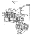
- Figs. 1 to 3 of the drawings there is illustrated a practical embodiment of a lubrication mechanism in a power transmission in accordance with the present invention.
- the power transmission includes an input shaft 10 rotatably mounted on an end wall of a housing 30 through a ball bearing 20 at its left-hand end in the figure.
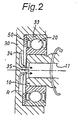
- an oil chamber R is formed in the end wall of housing 30 at the left-hand end of input shaft 10 as shown in Fig. 2 to store an amount of lubrication oil supplied through an oil supply passage 31 formed in the end wall of housing 30 as shown in Fig. 3.
- the lubrication oil is collected in a conventional manner and introduced into the oil supply passage 31 and any excess amount of the lubrication oil is discharged through an exhaust passage 32 formed in the end wall of housing 30.
- the lubrication oil discharged from the exhaust passage 32 is circulated into an oil reservoir (not shown) of the transmission in a conventional manner.
- three change-speed gears 41, 42, 43 are rotatably mounted on the input shaft 10 through needle bearings and, as shown in Fig. 2, an axial oil passage 11 is formed in the left-hand portion of input shaft 10 to supply therethrough the lubrication oil from the oil chamber R into the supported portions of change-speed gears 41, 42, 43.
- the input shaft 10 is formed with axially spaced radial holes 12, 13 and 14 in communication with the axial oil passage 11 to permit the passage of lubrication oil therethrough to the supported portions of change-speed gears 41, 42 and 43.
- the ball bearing 20 is in the form of a sealed ball bearing coupled within a cylindrical mounting hole 33 in the end wall of housing 30 through an annular plate 50.
- the bearing 20 is positioned in place by engagement with the annular plate 50 to ensure the amount of lubrication oil supplied into the axial oil passage 11 from the oil chamber R.
- the end wall of housing 30 is formed at its internal surface with three circumferentially spaced spiral guide ridges 34 and a projection 35 located at the center of spiral guide ridges 34.
- the spiral guide ridges 34 are exposed to the interior of oil chamber R and oriented to spiral towards the center of input shaft 10 in a rotation direction of input shaft 10.
- the projection 35 protrudes into the axial oil passage 11 of input shaft 10 from the center of spiral guide ridges 34.
- the projection 35 protruding into the axial oil passage 11 of input shaft 10 is effective to introduce the flow of lubrication oil from the center of the spiral guide ridges 34 into the axial oil passage 11 of input shaft 10 for sufficient lubrication of the change-speed gears 41, 42, 43.
- the rotation of input shaft 10 is utilized to efficiently introduce the lubrication oil from the spiral guide ridges 34 into the axial oil passage 11, it is not necessary to provide the guide member for introduction of lubrication oil as in the conventional lubrication mechanism discussed above.
- the lubrication mechanism can be provided in a simple construction in a limited space of the power transmission.
- the center of spiral guide ridges 34 may be positioned coaxially with the center of input shaft 10 without the projection 35.
- the spiral guide ridges 34 have been spaced circumferentially at an appropriate distance, the number and arrangement of spiral guide ridges 34 may be modified in accordance with the internal construction of the power transmission.
Landscapes
- Engineering & Computer Science (AREA)
- General Engineering & Computer Science (AREA)
- Mechanical Engineering (AREA)
- General Details Of Gearings (AREA)
Abstract
Description
Claims (2)
- A lubrication mechanism in a power transmission of the type which includes a support shaft (10) rotatably mounted at one end thereof on an end wall of a housing (30) through a bearing (20) and a set of change-speed gears (41, 42, 43) mounted on the support shaft, wherein an oil chamber (R) formed by the bearing in the end wall of the housing at the one end of the support shaft is supplied with lubrication oil through an oil supply passage (31) formed in the end wall of the housing to supply the lubrication oil therefrom into an axial oil passage (11) of the support shaft for lubrication of the change-speed gears (41, 42, 43);
characterized in that the end wall of the housing (30) is formed at its internal surface with a plurality of circumferentially spaced spiral ridges (34) oriented towards the one end of the support shaft (10) in a rotation direction and exposed to the interior of the oil chamber (R); and in that the center of the spiral ridges is positioned coaxially with the axial oil passage (11) of the support shaft. - A lubrication mechanism as claimed in Claim 1, wherein a projection (35) formed at the center of the spiral ridges (34) protrudes into the axial oil passage (11) of the support shaft.
Applications Claiming Priority (2)
| Application Number | Priority Date | Filing Date | Title |
|---|---|---|---|
| JP24983098 | 1998-09-03 | ||
| JP24983098A JP4320066B2 (en) | 1998-09-03 | 1998-09-03 | Transmission lubrication mechanism |
Publications (3)
| Publication Number | Publication Date |
|---|---|
| EP0984207A2 true EP0984207A2 (en) | 2000-03-08 |
| EP0984207A3 EP0984207A3 (en) | 2000-09-13 |
| EP0984207B1 EP0984207B1 (en) | 2003-02-26 |
Family
ID=17198830
Family Applications (1)
| Application Number | Title | Priority Date | Filing Date |
|---|---|---|---|
| EP99202866A Expired - Lifetime EP0984207B1 (en) | 1998-09-03 | 1999-09-03 | Lubrication mechanism in power transmission |
Country Status (3)
| Country | Link |
|---|---|
| EP (1) | EP0984207B1 (en) |
| JP (1) | JP4320066B2 (en) |
| DE (1) | DE69905528T2 (en) |
Cited By (5)
| Publication number | Priority date | Publication date | Assignee | Title |
|---|---|---|---|---|
| EP1734269A1 (en) * | 2005-06-14 | 2006-12-20 | Getrag Ford Transmissions GmbH | Bearing with an oil funnel |
| US9587731B2 (en) | 2013-08-27 | 2017-03-07 | Kawasaki Jukogyo Kabushiki Kaisha | Lubricating apparatus for rotating shaft |
| US9945471B2 (en) | 2013-08-27 | 2018-04-17 | Kawasaki Jukogyo Kabushiki Kaisha | Lubricating apparatus for rotating shaft |
| CN112253733A (en) * | 2020-10-30 | 2021-01-22 | 重庆望江工业有限公司 | A sealing structure for the left end of the guide shaft of a wind turbine gearbox |
| EP3869070A1 (en) * | 2020-02-24 | 2021-08-25 | LG Electronics Inc. | Gear system |
Families Citing this family (10)
| Publication number | Priority date | Publication date | Assignee | Title |
|---|---|---|---|---|
| JP4570114B2 (en) * | 2000-12-13 | 2010-10-27 | アイシン・エーアイ株式会社 | Transmission lubrication mechanism |
| KR20020047609A (en) * | 2000-12-13 | 2002-06-22 | 이계안 | Lubrication structure of manual transmission |
| KR100528035B1 (en) * | 2002-10-16 | 2005-11-15 | 현대자동차주식회사 | Oil funnel of manual transmission |
| JP4891625B2 (en) * | 2006-02-10 | 2012-03-07 | 愛知機械工業株式会社 | Lubricating oil guide device |
| JP4926793B2 (en) | 2007-04-10 | 2012-05-09 | アイシン・エーアイ株式会社 | Transmission lubrication structure |
| JP2009197886A (en) * | 2008-02-21 | 2009-09-03 | Honda Motor Co Ltd | Oil introduction structure of rotary shaft |
| JP4697299B2 (en) | 2008-12-19 | 2011-06-08 | トヨタ自動車株式会社 | Oil supply mechanism of power transmission device |
| JP6725314B2 (en) * | 2016-05-16 | 2020-07-15 | 株式会社エクセディ | Lockup device for torque converter |
| KR101916592B1 (en) * | 2017-06-22 | 2018-11-07 | 현대다이모스(주) | Device for guiding oil into rotating shaft of manual transmission |
| JP2023010046A (en) * | 2021-07-08 | 2023-01-20 | トヨタ自動車株式会社 | Drive unit for vehicle |
Family Cites Families (5)
| Publication number | Priority date | Publication date | Assignee | Title |
|---|---|---|---|---|
| US4368802A (en) * | 1980-07-03 | 1983-01-18 | Rockwell International Corporation | Pressurized lubrication system |
| JPS58200899A (en) * | 1982-05-18 | 1983-11-22 | Toyota Motor Corp | Lubricating oil supply structure of bearing device in vehicle speed chenge gear |
| US4930601A (en) * | 1989-02-09 | 1990-06-05 | J. I. Case Company | Lubrication system for a transmission mechanism |
| US5154517A (en) * | 1991-04-17 | 1992-10-13 | Ina Bearing Company, Inc. | Anti-friction bearing with integral oil feed tube |
| US5667036A (en) * | 1996-05-21 | 1997-09-16 | New Venture Gear, Inc. | Lubrication system for transmissions |
-
1998
- 1998-09-03 JP JP24983098A patent/JP4320066B2/en not_active Expired - Fee Related
-
1999
- 1999-09-03 DE DE69905528T patent/DE69905528T2/en not_active Expired - Lifetime
- 1999-09-03 EP EP99202866A patent/EP0984207B1/en not_active Expired - Lifetime
Cited By (6)
| Publication number | Priority date | Publication date | Assignee | Title |
|---|---|---|---|---|
| EP1734269A1 (en) * | 2005-06-14 | 2006-12-20 | Getrag Ford Transmissions GmbH | Bearing with an oil funnel |
| US9587731B2 (en) | 2013-08-27 | 2017-03-07 | Kawasaki Jukogyo Kabushiki Kaisha | Lubricating apparatus for rotating shaft |
| US9945471B2 (en) | 2013-08-27 | 2018-04-17 | Kawasaki Jukogyo Kabushiki Kaisha | Lubricating apparatus for rotating shaft |
| EP3869070A1 (en) * | 2020-02-24 | 2021-08-25 | LG Electronics Inc. | Gear system |
| US11421777B2 (en) | 2020-02-24 | 2022-08-23 | Lg Magna E-Powertrain Co., Ltd. | Gear system |
| CN112253733A (en) * | 2020-10-30 | 2021-01-22 | 重庆望江工业有限公司 | A sealing structure for the left end of the guide shaft of a wind turbine gearbox |
Also Published As
| Publication number | Publication date |
|---|---|
| JP4320066B2 (en) | 2009-08-26 |
| DE69905528T2 (en) | 2003-11-06 |
| EP0984207A3 (en) | 2000-09-13 |
| DE69905528D1 (en) | 2003-04-03 |
| EP0984207B1 (en) | 2003-02-26 |
| JP2000081117A (en) | 2000-03-21 |
Similar Documents
| Publication | Publication Date | Title |
|---|---|---|
| EP0984207B1 (en) | Lubrication mechanism in power transmission | |
| US4615231A (en) | Planetary gear unit | |
| GB2048397A (en) | Spigot bearing lubrication | |
| US5597370A (en) | Lubricating device for a planetary gear unit | |
| JP2015165148A (en) | Conical roller bearing | |
| US10967845B2 (en) | Drive-force transmitting apparatus for vehicle | |
| KR101003941B1 (en) | Automatic transmission | |
| EP0743467B1 (en) | One-way clutch | |
| US4821602A (en) | Support structure of differential gear unit | |
| JP3625139B2 (en) | Lubrication structure of automatic transmission | |
| US20060257062A1 (en) | Lubricating mechanism for a transfer | |
| JP7820528B2 (en) | Electric drive gearbox assembly positioned with stepped bore | |
| CN107503842A (en) | The idle pulley of fastener-free | |
| JP2001153212A (en) | Planetary gear set | |
| US6699020B1 (en) | Fan assembly with lubricant-containing bearings | |
| JP2017166495A (en) | Lubrication structure of pinion carrier | |
| JP4824459B2 (en) | Mechanical clutch unit | |
| US5609538A (en) | Lubricating device for a planetary gear unit | |
| US7748499B2 (en) | Lubrication flow control mechanism and method | |
| US20230011738A1 (en) | Vehicle driving apparatus | |
| JP4260401B2 (en) | One-way clutch | |
| JP2003106383A (en) | Epicycloidal speed change gear | |
| JP2001124157A (en) | Lubrication structure of planetary gear mechanism | |
| CN212536608U (en) | Gearbox bearing seat, gearbox and vehicle | |
| US12188550B1 (en) | Differential with improved lubrication |
Legal Events
| Date | Code | Title | Description |
|---|---|---|---|
| PUAI | Public reference made under article 153(3) epc to a published international application that has entered the european phase |
Free format text: ORIGINAL CODE: 0009012 |
|
| AK | Designated contracting states |
Kind code of ref document: A2 Designated state(s): DE FR GB |
|
| AX | Request for extension of the european patent |
Free format text: AL;LT;LV;MK;RO;SI |
|
| PUAL | Search report despatched |
Free format text: ORIGINAL CODE: 0009013 |
|
| AK | Designated contracting states |
Kind code of ref document: A3 Designated state(s): AT BE CH CY DE DK ES FI FR GB GR IE IT LI LU MC NL PT SE |
|
| AX | Request for extension of the european patent |
Free format text: AL;LT;LV;MK;RO;SI |
|
| AKX | Designation fees paid | ||
| REG | Reference to a national code |
Ref country code: DE Ref legal event code: 8566 |
|
| 17P | Request for examination filed |
Effective date: 20010516 |
|
| RBV | Designated contracting states (corrected) |
Designated state(s): DE FR GB |
|
| GRAH | Despatch of communication of intention to grant a patent |
Free format text: ORIGINAL CODE: EPIDOS IGRA |
|
| GRAH | Despatch of communication of intention to grant a patent |
Free format text: ORIGINAL CODE: EPIDOS IGRA |
|
| GRAA | (expected) grant |
Free format text: ORIGINAL CODE: 0009210 |
|
| AK | Designated contracting states |
Designated state(s): DE FR GB |
|
| REG | Reference to a national code |
Ref country code: GB Ref legal event code: FG4D |
|
| REF | Corresponds to: |
Ref document number: 69905528 Country of ref document: DE Date of ref document: 20030403 Kind code of ref document: P |
|
| ET | Fr: translation filed | ||
| PLBE | No opposition filed within time limit |
Free format text: ORIGINAL CODE: 0009261 |
|
| STAA | Information on the status of an ep patent application or granted ep patent |
Free format text: STATUS: NO OPPOSITION FILED WITHIN TIME LIMIT |
|
| 26N | No opposition filed |
Effective date: 20031127 |
|
| PGFP | Annual fee paid to national office [announced via postgrant information from national office to epo] |
Ref country code: DE Payment date: 20110920 Year of fee payment: 13 Ref country code: FR Payment date: 20111004 Year of fee payment: 13 Ref country code: GB Payment date: 20110926 Year of fee payment: 13 |
|
| GBPC | Gb: european patent ceased through non-payment of renewal fee |
Effective date: 20120903 |
|
| REG | Reference to a national code |
Ref country code: FR Ref legal event code: ST Effective date: 20130531 |
|
| PG25 | Lapsed in a contracting state [announced via postgrant information from national office to epo] |
Ref country code: GB Free format text: LAPSE BECAUSE OF NON-PAYMENT OF DUE FEES Effective date: 20120903 Ref country code: DE Free format text: LAPSE BECAUSE OF NON-PAYMENT OF DUE FEES Effective date: 20130403 |
|
| REG | Reference to a national code |
Ref country code: DE Ref legal event code: R119 Ref document number: 69905528 Country of ref document: DE Effective date: 20130403 |
|
| PG25 | Lapsed in a contracting state [announced via postgrant information from national office to epo] |
Ref country code: FR Free format text: LAPSE BECAUSE OF NON-PAYMENT OF DUE FEES Effective date: 20121001 |