EP0984211A2 - Dispositif pour assister la rotation d'un arbre - Google Patents
Dispositif pour assister la rotation d'un arbre Download PDFInfo
- Publication number
- EP0984211A2 EP0984211A2 EP99890244A EP99890244A EP0984211A2 EP 0984211 A2 EP0984211 A2 EP 0984211A2 EP 99890244 A EP99890244 A EP 99890244A EP 99890244 A EP99890244 A EP 99890244A EP 0984211 A2 EP0984211 A2 EP 0984211A2
- Authority
- EP
- European Patent Office
- Prior art keywords
- shift
- rotary shaft
- working cylinder
- lever
- shaft
- Prior art date
- Legal status (The legal status is an assumption and is not a legal conclusion. Google has not performed a legal analysis and makes no representation as to the accuracy of the status listed.)
- Withdrawn
Links
Images


Classifications
-
- F—MECHANICAL ENGINEERING; LIGHTING; HEATING; WEAPONS; BLASTING
- F16—ENGINEERING ELEMENTS AND UNITS; GENERAL MEASURES FOR PRODUCING AND MAINTAINING EFFECTIVE FUNCTIONING OF MACHINES OR INSTALLATIONS; THERMAL INSULATION IN GENERAL
- F16H—GEARING
- F16H61/00—Control functions within control units of change-speed- or reversing-gearings for conveying rotary motion ; Control of exclusively fluid gearing, friction gearing, gearings with endless flexible members or other particular types of gearing
- F16H61/26—Generation or transmission of movements for final actuating mechanisms
- F16H61/28—Generation or transmission of movements for final actuating mechanisms with at least one movement of the final actuating mechanism being caused by a non-mechanical force, e.g. power-assisted
- F16H61/30—Hydraulic or pneumatic motors or related fluid control means therefor
-
- F—MECHANICAL ENGINEERING; LIGHTING; HEATING; WEAPONS; BLASTING
- F16—ENGINEERING ELEMENTS AND UNITS; GENERAL MEASURES FOR PRODUCING AND MAINTAINING EFFECTIVE FUNCTIONING OF MACHINES OR INSTALLATIONS; THERMAL INSULATION IN GENERAL
- F16H—GEARING
- F16H61/00—Control functions within control units of change-speed- or reversing-gearings for conveying rotary motion ; Control of exclusively fluid gearing, friction gearing, gearings with endless flexible members or other particular types of gearing
- F16H61/26—Generation or transmission of movements for final actuating mechanisms
- F16H61/28—Generation or transmission of movements for final actuating mechanisms with at least one movement of the final actuating mechanism being caused by a non-mechanical force, e.g. power-assisted
-
- F—MECHANICAL ENGINEERING; LIGHTING; HEATING; WEAPONS; BLASTING
- F16—ENGINEERING ELEMENTS AND UNITS; GENERAL MEASURES FOR PRODUCING AND MAINTAINING EFFECTIVE FUNCTIONING OF MACHINES OR INSTALLATIONS; THERMAL INSULATION IN GENERAL
- F16H—GEARING
- F16H61/00—Control functions within control units of change-speed- or reversing-gearings for conveying rotary motion ; Control of exclusively fluid gearing, friction gearing, gearings with endless flexible members or other particular types of gearing
- F16H61/26—Generation or transmission of movements for final actuating mechanisms
- F16H61/28—Generation or transmission of movements for final actuating mechanisms with at least one movement of the final actuating mechanism being caused by a non-mechanical force, e.g. power-assisted
- F16H61/30—Hydraulic or pneumatic motors or related fluid control means therefor
- F16H2061/301—Hydraulic or pneumatic motors or related fluid control means therefor for power assistance, i.e. servos with follow up action
-
- F—MECHANICAL ENGINEERING; LIGHTING; HEATING; WEAPONS; BLASTING
- F16—ENGINEERING ELEMENTS AND UNITS; GENERAL MEASURES FOR PRODUCING AND MAINTAINING EFFECTIVE FUNCTIONING OF MACHINES OR INSTALLATIONS; THERMAL INSULATION IN GENERAL
- F16H—GEARING
- F16H61/00—Control functions within control units of change-speed- or reversing-gearings for conveying rotary motion ; Control of exclusively fluid gearing, friction gearing, gearings with endless flexible members or other particular types of gearing
- F16H61/26—Generation or transmission of movements for final actuating mechanisms
- F16H61/28—Generation or transmission of movements for final actuating mechanisms with at least one movement of the final actuating mechanism being caused by a non-mechanical force, e.g. power-assisted
- F16H61/30—Hydraulic or pneumatic motors or related fluid control means therefor
- F16H2061/308—Modular hydraulic shift units, i.e. preassembled actuator units for select and shift movements adapted for being mounted on transmission casing
Definitions
- the invention relates to a device for supporting the rotary movement a shaft, in particular for shift support for manual transmissions, especially for gear change transmissions of motor vehicles, especially from Commercial vehicles, with a manually operated shift lever, the indirect on the shaft and in particular with at least one shift finger provided rotary shaft acts indirectly on shift forks in the change gearbox, at least one pressure-actuated working cylinder on the shift linkage acts as a support, and at least one facility for investigation the actuation of the shift lever that controls the working cylinder.
- For switching support manual transmission there are several known solutions.
- Most of the shift support is firmly connected to the gearbox and the separation of rotary and transverse movement is achieved by sliding nuts, hollow and Spline shafts or the like.
- a first lever inside the housing guides the Forces on the valve and another lever then guides the generated one Power of the servo cylinder in the transmission.
- the shift linkage is fed directly onto the valve and the Decoupling between the rotary and transverse movements takes place only afterwards. about a sliding sleeve and an additional lever transmit the transverse movement.
- the Shift lever via a linkage with a control rod in the piston rod connected to a servo cylinder, which increases the switching forces proportionally transmits into the transmission.
- a control rod in the piston rod connected to a servo cylinder
- DE-0S 29 27 666 describes a switching support in which a relative rotation of the shift lever and rotary shaft via an inner Lever arm is transferred to a valve assembly, which is then the servo cylinder controls.
- the rotating shaft itself remains stationary.
- the US-PS 2,926,539 has the subject of a switching device in which the movement of the shift lever via a shaft in an actuation movement a control valve is implemented.
- the control valve then controls one Actuator on, which in turn the switching movement of a fixed overall second rotary shaft.
- the switching device of US Pat. Nos. 3,035,102 functions similarly and 3,074,291, in which the switching movement of the shift lever for actuation leads from switching valves, which then switching actuators for rotating the Activate the actual and in turn completely stationary rotary shaft.
- the aim of the present invention was a structurally not complex Support device, in particular for the switching support of Gearboxes, which also have the best possible characteristics in operation Emergency operation, i.e. the emergency switchability for transmissions, not for failure impaired and preferably also for retrofitting existing ones System and gear is suitable.
- control valves or the working cylinders and any Servo lever, preferably all components mentioned, between the driver finger and the movable mounting of the rotary shaft are provided, allows one very compact and small dimensioned version of the invention Rotation or switching support.
- pneumatic seat valves with a low level are possible Hub provided to control the or each working cylinder, which over an elastic element, preferably a coil spring, closed are held and wherein further elastic elements, preferably coil springs, keep the rotating shaft in its neutral position. So that's especially with two opposing valves, the rotary shaft in the neutral position, in which the shift lever is not operated, between the actuators of the valves centered and damped held.
- an elastic element preferably a coil spring
- the or each control valve preferably also the or each working cylinder, arranged in a common housing, which also the bearing for the pivotable storage in the direction of the switching movement includes the rotating shaft and preferably with that on the gear housing flanged switch boom housing is connected.
- a shift cylinder preferably a hydraulic working cylinder, a hydraulic one Switching system parallel to the or each working cylinder on the rotating shaft acts.
- an additional one Shift cylinder, preferably a hydraulic working cylinder, of the hydraulic Switching system acts axially on the rotary shaft.
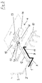
- FIG. 1 shows a perspective view of a transmission with flanged device for switching support
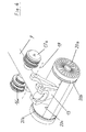
- Fig. 2 shows this device in an enlarged view Scale
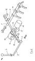
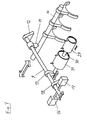
- Fig. 3 is a schematic perspective view of the inner structure the device and the connection to the shift linkage
- Fig. 4 shows an enlarged view of the end of the rotary shaft in a preferred Embodiment with a movable servo lever
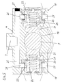
- Fig. 5 shows a cross section through the movable support of the rotating shaft, which with two symmetrical Valves for the working cylinder of the switching support is provided
- Fig. 6 is a schematic representation of the internal structure of a further embodiment
- Fig. 7 is a schematic illustration of the internal structure a further embodiment with hydraulic shift transmission.
- the device according to the invention in addition to the illustrated and especially for retrofitting existing gears, also structurally in the gearbox can be integrated.
- the introduction of force from the shift lever (not shown in FIG. 1) takes place via the outer gear lever 1, which is rotatably attached to the in the housing 2 extending rotary shaft is attached and its displacement in the axial Direction, depending on the shift gate selected with the shift lever.
- the Connection to the housing of the transmission G is advantageously in Area of the switch arm housing 3.
- the actually functional components the device according to the invention, namely the second bearing of the rotary shaft, the working cylinder supporting the switching movement and its control valves are advantageously located in a housing 4 on the gear lever 1 opposite side of the shift boom housing 3.
- FIG. 2 shows that the housing 4 is divided, being symmetrical to the rotary shaft and coaxial the two valve housings 5 are provided for the control valves, which as Working fluid for the working cylinder housed in the cylinder housing 6 preferably compressed air can be supplied via a connection 7.
- the Switch boom housing 3 is still the mounting flange 8 with the holes recognizable for the fastening screws.
- the internal structure of the device according to the invention is shown schematically in Fig. 3 shown, as well as the connection to the shift lever S via in between, here, for example, from just one straight section existing shift linkage Z, which engages the outer gear lever 1.
- This Gear lever 1 rotates one essentially across the movement of the shift lever S
- Rotary shaft 9 arranged when the gears are engaged.
- This rotary shaft 9 is between the gear lever 1 and one on the carrier 10 of the shift forks of the change-over gear driving finger 11 in a first bearing 12 stationary but rotatable and preferably also axially displaceable.
- the rotary shaft 9 is transverse to the longitudinal axis of the transmission, so that an axial displacement of this rotary shaft 9 a displacement transverse to Gearbox and its housing is G.
- the driving finger 11 is on the rotating shaft 9 rotatably mounted.
- K is the course of the power flow from the gear lever S referred to the carrier 10 of the shift forks.
- the rotary shaft 9 On the one opposite the first bearing 12 and the outer gear lever 1 Side of the driving finger 11, the rotary shaft 9 is continued and is provided with a servo lever 13 in the area of its end.
- a servo lever 13 which is rotatably connected to the rotary shaft 9 again, grip 3 two single-acting working cylinders 14, 15, preferably pneumatic cylinders with compressed air as the working fluid. Controlled these are working cylinders 14 and 15, which support the engagement of the gears, by two associated control valves 16 and 17, for example conventional poppet valves.
- the rotary shaft 9 on one from the first bearing 12 spaced point, preferably directly at the Control valves 16, 17, mounted in a second bearing 18 in such a way that them in the direction and in the plane of the switching movement, i.e. the direction of the Arrow V, can be pivoted. This can be done, for example, by a cross to the rotating shaft 9 and elongated hole parallel to the connecting line be realized.
- the rotary shaft 9 can directly or indirectly via intermediate pieces such as lever arrangements, plungers or the like the shut-off elements of the control valves 16, 17 act and thus the control of the support cylinders 14 and 15 effect.
- the servo arm 13, the working cylinders 14 and 15 and their control valves 16 and 17 are, as symbolized by the dash-dotted line, preferably arranged in a common housing 4, preferably with the shift boom housing 3 is connected.
- the rotary shaft 9 is also preferred axially displaceable in order to move the shift lever S accordingly Choice of different switching gates lying side by side, these Movement to let the axis of rotation 9 communicate.
- the servo lever 13 as shown in Fig. 4 is rotationally fixed, but about an axis 19 running transverse to the rotary shaft 9 pivotable, is mounted on the rotary shaft 9.
- the servo lever 13 then has another effective Length on, so that the force of the working cylinder remains the same for switching support is different.
- the servo lever 13 but also always with the same angle to the axis of the rotary shaft 9 on this be mounted, to enable the axial displacement of this rotary shaft 9 it is passed through a bore in the servo lever 13.
- the Prevention of mutual twisting is done, for example, via a Groove-pin arrangement accomplished, preferably at least one axial Longitudinal groove in the rotary shaft 9 and one corresponding to the number of grooves Number of pins engaging in these grooves in the bore of the servo lever 13 are worked out.
- Fig. 4 it can also be seen that of course instead of two single-acting working cylinders 14, 15 also a double-acting Working cylinder can be provided, of which only the piston 20 in FIG. 4 with its pressurized surfaces 20a, the piston seals and guide rings 20b and the guideway 20c for preferably with one spherical end servo lever 13 is shown.
- a double-acting Working cylinder of which only the piston 20 in FIG. 4 with its pressurized surfaces 20a, the piston seals and guide rings 20b and the guideway 20c for preferably with one spherical end servo lever 13 is shown.
- the control valves 16 and 17 for the double-acting cylinder even only the actual valve elements 16a and 17a without the surrounding one Housing shown.
- FIG. 5 is a preferred embodiment for the the pivoting of the rotary shaft 9 bearing in the form of an elongated hole 18 shown in the housing 4, in which the control valves 16 and 17 are located.
- Each control valve 16, 17 has one as functional components Valve piston 21 on by a coil spring 22 or equivalent is applied to the elastic element in the direction of the rotary shaft 9, so that it rests on a stop in the housing 4. If no force on the Rotating shaft 9 acts to pivot it, it is by the two Valve piston 21 centered in a neutral center position.
- FIG. 6 The internal structure of a further embodiment of the invention
- the device is shown schematically in FIG. 6.
- the connection is made again to the shift lever S via an intermediate one, here as an example only a straight section existing shift linkage Z, the outer Gear lever 1 attacks.
- This gear lever 1 essentially rotates arranged transversely to the movement of the shift lever S when the gears are engaged Rotary shaft 9 with on the carrier 10 of the shift forks of the change gear acting driving fingers 11.
- the first bearing 12 for stationary, but rotatable and preferably also axially displaceable mounting of the rotary shaft 9 on the Gear lever 1 opposite end of the rotary shaft 9.
- the second bearing 18 is provided for the rotary shaft 9, in which it is stored in such a way that it is in the direction and in the plane of the Switching movement can be pivoted.
- This can be done for example by a oblong hole oriented transversely to the rotary shaft 9.
- Fig. 7 shows schematically an embodiment for use with a hydraulic transmission of the switching movement from the shift lever S (here not shown) in the transmission.
- a hydraulic cylinder 29 is provided, which is a conventional hydraulic Power transmission system is connected to the shift lever.
- This Hydraulic cylinder 29 is in the exemplary embodiment shown connected to the double-acting working cylinder 31 via a piston rod 30, which again to support the switching movement on the servo lever 13 of the rotary shaft 9 acts.
- the two associated control valves 16 and 17 are now exemplary on the side of the bearing 18 opposite the servo lever 13, in which the Rotary shaft 9 is pivotally mounted in the switching direction. Now with this one Arrangement of the working cylinder 31 when activated by one of the control valves 16 or 17 in addition to supporting the rotary movement of the rotary shaft 6 also this pivoting must be further intensified, for example by means of a corresponding countermeasuring characteristic of the control valves 16 and 17 are taken into account and a counteraction is generated.
Landscapes
- Engineering & Computer Science (AREA)
- General Engineering & Computer Science (AREA)
- Mechanical Engineering (AREA)
- Gear-Shifting Mechanisms (AREA)
Applications Claiming Priority (2)
| Application Number | Priority Date | Filing Date | Title |
|---|---|---|---|
| AT144898 | 1998-08-26 | ||
| AT144898 | 1998-08-26 |
Publications (2)
| Publication Number | Publication Date |
|---|---|
| EP0984211A2 true EP0984211A2 (fr) | 2000-03-08 |
| EP0984211A3 EP0984211A3 (fr) | 2001-04-04 |
Family
ID=3514119
Family Applications (1)
| Application Number | Title | Priority Date | Filing Date |
|---|---|---|---|
| EP99890244A Withdrawn EP0984211A3 (fr) | 1998-08-26 | 1999-07-21 | Dispositif pour assister la rotation d'un arbre |
Country Status (5)
| Country | Link |
|---|---|
| EP (1) | EP0984211A3 (fr) |
| JP (1) | JP2000074209A (fr) |
| KR (1) | KR20000017444A (fr) |
| CN (1) | CN1247950A (fr) |
| BR (1) | BR9903894A (fr) |
Cited By (1)
| Publication number | Priority date | Publication date | Assignee | Title |
|---|---|---|---|---|
| WO2002033290A1 (fr) * | 2000-10-19 | 2002-04-25 | Scania Cv Ab (Publ) | Mecanisme de changement de vitesses pour un vehicule a moteur |
Families Citing this family (1)
| Publication number | Priority date | Publication date | Assignee | Title |
|---|---|---|---|---|
| CN103527763A (zh) * | 2013-10-30 | 2014-01-22 | 长城汽车股份有限公司 | 换挡机构及具有该换挡机构的变速器 |
Family Cites Families (2)
| Publication number | Priority date | Publication date | Assignee | Title |
|---|---|---|---|---|
| DE1176000B (de) * | 1957-03-19 | 1964-08-13 | Saurer Ag Adolph | Mit Druckmittel arbeitende Hilfskraftschalt-vorrichtung fuer Kraftfahrzeug-Wechselgetriebe |
| SE410951B (sv) * | 1978-07-10 | 1979-11-19 | Saab Scania Ab | Anordning for att underletta vexling vid manuellt manovrerbara vexellador |
-
1999
- 1999-07-21 EP EP99890244A patent/EP0984211A3/fr not_active Withdrawn
- 1999-08-23 KR KR1019990034863A patent/KR20000017444A/ko not_active Withdrawn
- 1999-08-25 CN CN99118084A patent/CN1247950A/zh active Pending
- 1999-08-25 JP JP11238607A patent/JP2000074209A/ja active Pending
- 1999-08-26 BR BR9903894-3A patent/BR9903894A/pt not_active Application Discontinuation
Cited By (2)
| Publication number | Priority date | Publication date | Assignee | Title |
|---|---|---|---|---|
| WO2002033290A1 (fr) * | 2000-10-19 | 2002-04-25 | Scania Cv Ab (Publ) | Mecanisme de changement de vitesses pour un vehicule a moteur |
| US6874382B2 (en) | 2000-10-19 | 2005-04-05 | Scania Cv Ab (Publ) | Software controlled gear change mechanism for a motor vehicle |
Also Published As
| Publication number | Publication date |
|---|---|
| CN1247950A (zh) | 2000-03-22 |
| EP0984211A3 (fr) | 2001-04-04 |
| KR20000017444A (ko) | 2000-03-25 |
| BR9903894A (pt) | 2000-09-19 |
| JP2000074209A (ja) | 2000-03-14 |
Similar Documents
| Publication | Publication Date | Title |
|---|---|---|
| DE4127991C2 (de) | Parksperre für automatische Getriebe von Kraftfahrzeugen | |
| EP2153089B1 (fr) | Dispositif de changement de vitesse pour une boîte de vitesses d'un véhicule à moteur | |
| EP2220404B1 (fr) | Dispositif d'assistance pour boite de vitesses de vehicule automobile | |
| EP0731297B1 (fr) | Système d'actionneurs pour boite de vitesses de véhicule | |
| DE2927666C2 (fr) | ||
| DE112007000784T5 (de) | Vorrichtung und Verfahren zum Gangwechsel in mechanischen Getrieben | |
| EP0731298B1 (fr) | Système d'actionneurs pour boite de vitesses de véhicule | |
| EP0984210A2 (fr) | Dispositif pour assister la rotation d'un arbre | |
| EP0500622B1 (fr) | Dispositif d'entrainement pour un arbre a cames loge dans la culasse d'un moteur a combustion interne | |
| WO2017153032A1 (fr) | Boîte de vitesses automatique | |
| DE102004025593A1 (de) | Arretierhebelanordnung für ein internes elektronisches System zur Auswahl von Getriebebereichen (ETRS) | |
| DE102006059029B4 (de) | Drehschieber | |
| DE2842736A1 (de) | Schalteinrichtung fuer getriebe | |
| DE102006049283A1 (de) | Vorrichtung zum drehfesten Verbinden einer Welle mit wenigstens einem drehbar auf der Welle gelagerten Bauteil | |
| DE102011119833B4 (de) | Schaltvorrichtung für Doppelkupplungsgetriebe in Kraftfahrzeugen | |
| EP2059695B1 (fr) | Dispositif de changement de vitesse pour une boîte de vitesses de véhicule automobile | |
| DE19861137C2 (de) | Stelleinrichtung zur automatisierten Betätigung eines Schaltgetriebes | |
| EP0984211A2 (fr) | Dispositif pour assister la rotation d'un arbre | |
| DE102016201719A1 (de) | Schaltvorrichtung | |
| EP0879335B1 (fr) | Ferme-porte et procede permettant de faire fonctionner un ferme-porte | |
| DE102014203352B4 (de) | Zapfwellengetriebe | |
| DE102017003400A1 (de) | Dreistellungsaktuator für ein automatisiertes Schaltgetriebe | |
| EP1744075B1 (fr) | Dispositif de commande avec un levier balancant, en particulier pour un embrayage | |
| DE19710121C2 (de) | Vorrichtung zum elektromechanischen Schalten eines Gangwechselgetriebes | |
| DE102006015886B4 (de) | Wipphebelaktor, insbesondere zur Betätigung einer Kupplung |
Legal Events
| Date | Code | Title | Description |
|---|---|---|---|
| PUAI | Public reference made under article 153(3) epc to a published international application that has entered the european phase |
Free format text: ORIGINAL CODE: 0009012 |
|
| AK | Designated contracting states |
Kind code of ref document: A2 Designated state(s): AT BE CH CY DE DK ES FI FR GB GR IE IT LI LU MC NL PT SE |
|
| AX | Request for extension of the european patent |
Free format text: AL;LT;LV;MK;RO;SI |
|
| PUAL | Search report despatched |
Free format text: ORIGINAL CODE: 0009013 |
|
| AK | Designated contracting states |
Kind code of ref document: A3 Designated state(s): AT BE CH CY DE DK ES FI FR GB GR IE IT LI LU MC NL PT SE |
|
| AX | Request for extension of the european patent |
Free format text: AL;LT;LV;MK;RO;SI |
|
| AKX | Designation fees paid | ||
| REG | Reference to a national code |
Ref country code: DE Ref legal event code: 8566 |
|
| STAA | Information on the status of an ep patent application or granted ep patent |
Free format text: STATUS: THE APPLICATION IS DEEMED TO BE WITHDRAWN |
|
| 18D | Application deemed to be withdrawn |
Effective date: 20011005 |