EP0984226B1 - Méthode pour produire de l'eau chaude sanitaire et de chauffage et installation de chauffage compacte associée - Google Patents
Méthode pour produire de l'eau chaude sanitaire et de chauffage et installation de chauffage compacte associée Download PDFInfo
- Publication number
- EP0984226B1 EP0984226B1 EP98810876A EP98810876A EP0984226B1 EP 0984226 B1 EP0984226 B1 EP 0984226B1 EP 98810876 A EP98810876 A EP 98810876A EP 98810876 A EP98810876 A EP 98810876A EP 0984226 B1 EP0984226 B1 EP 0984226B1
- Authority
- EP
- European Patent Office
- Prior art keywords
- heat
- heat exchanger
- heating
- transfer fluid
- water
- Prior art date
- Legal status (The legal status is an assumption and is not a legal conclusion. Google has not performed a legal analysis and makes no representation as to the accuracy of the status listed.)
- Revoked
Links
- 238000000034 method Methods 0.000 title claims abstract description 17
- 238000010438 heat treatment Methods 0.000 title claims description 49
- 239000008236 heating water Substances 0.000 title claims description 25
- XLYOFNOQVPJJNP-UHFFFAOYSA-N water Substances O XLYOFNOQVPJJNP-UHFFFAOYSA-N 0.000 claims abstract description 12
- 230000006835 compression Effects 0.000 claims abstract description 9
- 238000007906 compression Methods 0.000 claims abstract description 9
- 230000008569 process Effects 0.000 claims abstract description 7
- 239000003651 drinking water Substances 0.000 claims description 29
- 235000020188 drinking water Nutrition 0.000 claims description 28
- 239000013529 heat transfer fluid Substances 0.000 claims description 25
- 238000000429 assembly Methods 0.000 claims description 5
- 230000003247 decreasing effect Effects 0.000 claims 2
- 239000012530 fluid Substances 0.000 abstract description 17
- 239000007788 liquid Substances 0.000 description 8
- 238000010586 diagram Methods 0.000 description 5
- 239000003570 air Substances 0.000 description 3
- 230000008901 benefit Effects 0.000 description 3
- 230000000712 assembly Effects 0.000 description 2
- 230000008878 coupling Effects 0.000 description 2
- 238000010168 coupling process Methods 0.000 description 2
- 238000005859 coupling reaction Methods 0.000 description 2
- 239000000523 sample Substances 0.000 description 2
- 239000002689 soil Substances 0.000 description 2
- 210000002023 somite Anatomy 0.000 description 2
- 230000009182 swimming Effects 0.000 description 2
- 238000012546 transfer Methods 0.000 description 2
- 238000009423 ventilation Methods 0.000 description 2
- 230000002776 aggregation Effects 0.000 description 1
- 238000004220 aggregation Methods 0.000 description 1
- 239000012080 ambient air Substances 0.000 description 1
- 230000002308 calcification Effects 0.000 description 1
- 238000004140 cleaning Methods 0.000 description 1
- 238000009833 condensation Methods 0.000 description 1
- 230000005494 condensation Effects 0.000 description 1
- 238000001816 cooling Methods 0.000 description 1
- 238000013461 design Methods 0.000 description 1
- 230000004069 differentiation Effects 0.000 description 1
- 230000035622 drinking Effects 0.000 description 1
- 230000007613 environmental effect Effects 0.000 description 1
- 239000003673 groundwater Substances 0.000 description 1
- 230000017525 heat dissipation Effects 0.000 description 1
- 230000006872 improvement Effects 0.000 description 1
- 238000009434 installation Methods 0.000 description 1
- 238000012423 maintenance Methods 0.000 description 1
- 238000004519 manufacturing process Methods 0.000 description 1
- 238000005259 measurement Methods 0.000 description 1
- 238000002156 mixing Methods 0.000 description 1
- 238000002360 preparation method Methods 0.000 description 1
- 230000005855 radiation Effects 0.000 description 1
- 230000009467 reduction Effects 0.000 description 1
- 230000000630 rising effect Effects 0.000 description 1
- 230000011664 signaling Effects 0.000 description 1
- 230000007704 transition Effects 0.000 description 1
- 239000002351 wastewater Substances 0.000 description 1
Images

Classifications
-
- F—MECHANICAL ENGINEERING; LIGHTING; HEATING; WEAPONS; BLASTING
- F24—HEATING; RANGES; VENTILATING
- F24D—DOMESTIC- OR SPACE-HEATING SYSTEMS, e.g. CENTRAL HEATING SYSTEMS; DOMESTIC HOT-WATER SUPPLY SYSTEMS; ELEMENTS OR COMPONENTS THEREFOR
- F24D3/00—Hot-water central heating systems
- F24D3/18—Hot-water central heating systems using heat pumps
-
- F—MECHANICAL ENGINEERING; LIGHTING; HEATING; WEAPONS; BLASTING
- F24—HEATING; RANGES; VENTILATING
- F24D—DOMESTIC- OR SPACE-HEATING SYSTEMS, e.g. CENTRAL HEATING SYSTEMS; DOMESTIC HOT-WATER SUPPLY SYSTEMS; ELEMENTS OR COMPONENTS THEREFOR
- F24D19/00—Details
- F24D19/10—Arrangement or mounting of control or safety devices
- F24D19/1006—Arrangement or mounting of control or safety devices for water heating systems
- F24D19/1066—Arrangement or mounting of control or safety devices for water heating systems for the combination of central heating and domestic hot water
- F24D19/1072—Arrangement or mounting of control or safety devices for water heating systems for the combination of central heating and domestic hot water the system uses a heat pump
-
- F—MECHANICAL ENGINEERING; LIGHTING; HEATING; WEAPONS; BLASTING
- F24—HEATING; RANGES; VENTILATING
- F24D—DOMESTIC- OR SPACE-HEATING SYSTEMS, e.g. CENTRAL HEATING SYSTEMS; DOMESTIC HOT-WATER SUPPLY SYSTEMS; ELEMENTS OR COMPONENTS THEREFOR
- F24D3/00—Hot-water central heating systems
- F24D3/08—Hot-water central heating systems in combination with systems for domestic hot-water supply
-
- Y—GENERAL TAGGING OF NEW TECHNOLOGICAL DEVELOPMENTS; GENERAL TAGGING OF CROSS-SECTIONAL TECHNOLOGIES SPANNING OVER SEVERAL SECTIONS OF THE IPC; TECHNICAL SUBJECTS COVERED BY FORMER USPC CROSS-REFERENCE ART COLLECTIONS [XRACs] AND DIGESTS
- Y02—TECHNOLOGIES OR APPLICATIONS FOR MITIGATION OR ADAPTATION AGAINST CLIMATE CHANGE
- Y02B—CLIMATE CHANGE MITIGATION TECHNOLOGIES RELATED TO BUILDINGS, e.g. HOUSING, HOUSE APPLIANCES OR RELATED END-USER APPLICATIONS
- Y02B30/00—Energy efficient heating, ventilation or air conditioning [HVAC]
- Y02B30/12—Hot water central heating systems using heat pumps
-
- Y—GENERAL TAGGING OF NEW TECHNOLOGICAL DEVELOPMENTS; GENERAL TAGGING OF CROSS-SECTIONAL TECHNOLOGIES SPANNING OVER SEVERAL SECTIONS OF THE IPC; TECHNICAL SUBJECTS COVERED BY FORMER USPC CROSS-REFERENCE ART COLLECTIONS [XRACs] AND DIGESTS
- Y02—TECHNOLOGIES OR APPLICATIONS FOR MITIGATION OR ADAPTATION AGAINST CLIMATE CHANGE
- Y02B—CLIMATE CHANGE MITIGATION TECHNOLOGIES RELATED TO BUILDINGS, e.g. HOUSING, HOUSE APPLIANCES OR RELATED END-USER APPLICATIONS
- Y02B30/00—Energy efficient heating, ventilation or air conditioning [HVAC]
- Y02B30/52—Heat recovery pumps, i.e. heat pump based systems or units able to transfer the thermal energy from one area of the premises or part of the facilities to a different one, improving the overall efficiency
Definitions
- the invention relates to a method for producing hot drinking and heating water and a heating arrangement or compact heating arrangement therefor.
- the internal heating of the FR-A 2 679 016 had several heating lines through which The heat transfer fluid is controlled individually via electromagnetic valves was transportable.
- the valves at the end of each heating line acted as Expansion valves.
- the outputs of the valves were in a pipe system summarized, which is a connection to a distributor and another Pressure reducing valve, the outlet of which led to a heat exchanger, via the Heat from used service water (waste water) was absorbed.
- the Output of the distributor led to a register, the output of which corresponds to the input of the Compressor heat pump was connected.
- the pipe system could use another one Pressure reducing valve connected to recover heat from the air become.
- the object of the invention is a method with a compression heat pump process to show, in which an optimal heating of drinking water as well of the heating water for heating if possible with a minimal heating arrangement is achieved.
- the object is achieved in that the heat transport fluid of a compression heat pump arrangement always first through the heat exchanger for that warm drinking water and only then depending on the remaining heat Heating the heating water is used.
- the heat transfer fluid flows through however, always directly the heat exchanger for the drinking water and, if sufficient Residual heat is present, then directly for the heating water.
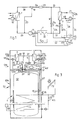
- the heat flow image representation in FIG. 1 for the arrangement or compact heating arrangement according to the invention represents a compression heat pump arrangement.
- the arrangement has a first heat exchanger 1 for producing warm drinking water. Furthermore, it has a second heat exchanger 3 for generating hot heating water and a bypass 5 with which this heat exchanger 3 can be bridged.
- a third heat exchanger 7 is connected to a heat source 9 , not shown, whose heat transfer fluid is transported by a pump 10 from the heat source 9 to the heat exchanger 7 .
- the soil is preferably used as a heat source by means of a probe system or a surface collector, because the environmental energy necessary for the entire heat supply of a house is available permanently and with high efficiency.
- the connection to a ventilation system is also possible.
- the arrangement has a compressor 11 , a hot water boiler 13 with the heat exchanger 1 and a measuring device 15 , two solenoid valves 17a and 17b , an expansion valve 19 , a control device 21 , a filter dryer 23 and a further measuring device 25 , which in the return 27 of the heating water is arranged to measure its temperature.
- the expansion valve 19 is connected to the inlet of the compressor 11 via a line 20 (usually a capillary). This connection is used to adjust the pressure of the heat transfer fluid.
- the outlet of the heat exchanger 7 is connected to the inlet of the compressor 11 via a pipe 29 .
- the output of the compressor 11 leads via line 31 to the input of the heat exchanger 1.
- the output of the heat exchanger 1 is connected to the line 32 via the solenoid valve 17b to the input of the heat exchanger 3 and its output via line 33 to the input of the filter dryer 23 ,
- the inlet and outlet of the heat exchanger 3 can be bridged with the bypass 5 , as already explained above.
- the solenoid valve 17 a is arranged in the bypass 5 .
- the output of the filter dryer 23 is connected via line 34 to the input of the expansion valve 19 and its output via line 35 to the input of the heat exchanger 7 .
- the signaling device is the control device 21 via line 39 with the temperature measuring device 25 in the heating return 27 , with an outside temperature measuring device 40 via line 41 , with the temperature measuring device 15 in the boiler 13 via line 42 , with a frequency converter 44 via line 45 , with a pump 43 connected to one of the two solenoid valves 17a and 17b in the heating flow 46 via a line 48 and via lines 47a and 47b .
- a preferably changeable alternating current frequency for driving the compressor 11 can be generated with the frequency converter. The higher the frequency, the faster the pump motor of the compressor 11 runs and the higher the compressor output.
- the frequency converter 44 is connected to the compressor via the electrical line 49 . That is, the compressor 11 is adjustable in speed. This allows a significant improvement in the performance figures to be achieved in the partial load range. Another advantage is that the compressor 11 only has to be designed for the output in the control heating range and only the demand peaks at very low outside temperatures can be covered by corresponding speed increases.
- the solenoid valve 17a in the bypass 5 When operating only to produce warm drinking water, the solenoid valve 17a in the bypass 5 is completely open and the solenoid valve 17b in the line 32 to the heat exchanger 3 for the heating water is completely closed. No heat transfer fluid flows through the heat exchanger for the heating water.
- the wet fluid vapor absorbs heat in the heat exchanger 7 , which is supplied by the above-mentioned probe system 9 .
- this results in a movement from point F in the wet steam area over curve 53 to point A in the dry steam area.
- the temperature of the drinking water in the boiler 13 now rises above a predetermined temperature (for example 65 ° C.) due to the heat given off by the heat exchanger 1 arranged in the boiler 13 , the heat given off in the heat exchanger 1 is reduced, as a result of which point E "slips back" into the wet steam area.
- the predetermined temperature is stored in a memory of the control device 21 .
- the actual temperature of the drinking water as an indirect measure of the residual heat of the heat transfer fluid leaving the heat exchanger 1 is compared with this predetermined (stored) temperature. When exceeding this predetermined temperature by the actual temperature opens the solenoid valve 17b via the control line 47b from the controller 21 and the solenoid valve 17a closes the bypass 5 via the control line 47 a.
- the heat transfer fluid now flows through the heat exchanger 3 for additional heating of the heating water.
- the control device 21 starts the pump 43 in the heating flow 46 via the control line 48 (the pump 43 can of course always be in operation).
- the heat transfer fluid cools due to the release of heat in the heat exchanger 3 and leaves the heat exchanger 3 through the line 33 as wet steam or as a liquid (point E in FIG. 2 ).
- the rest of the process is analogous to what was said above.
- the high temperature level of the heat transport fluid present at the outlet of the compressor 11 can always be used for the preparation of warm drinking water.
- the heating of drinking water and heating water is designed in such a way by the control device 21 that the heating of drinking water always has priority.
- the drinking water temperature is determined with the temperature measuring device 15 , as already mentioned above.
- the sensor belonging to the measuring device 15 is preferably arranged in the lower third of the boiler 13 .
- the temperature of the heating water is determined using the temperature measuring device 25 , ie its measuring sensor in the return 27 .
- the outside sensor 40 is used in particular to specify a value for the return temperature of the heating water, taking into account the measured outside temperature.
- the control device 21 then increases the current frequency for the compressor 11 through the frequency converter 44 by means of a signal. This increases the compressor output and results in a higher heat flow. Since the compressor 11 is speed-controllable, the system can normally be operated in a part-load range, ie in a control heating mode. The need peaks at very low outside temperatures then only have to be covered by a corresponding increase in speed. If this cover, which is only necessary for a few days, is to be dispensed with, an adjustable frequency converter 44 is not required. This design of the heating arrangement, in which the components are designed not for the peak, but for the regular heating operation, allows the components to be minimized, which results in a significant cost reduction in terms of purchase and installation.
- bypass 5 It is also not always necessary to switch completely between bypass 5 and a flow through heat exchanger 3 , it is also possible to send only a partial flow of heat fluid through the bypass and heat exchanger 3 .
- a partial shutdown of the heating circuit could also be carried out, e.g. B. in the way that certain rooms would only be heated at predetermined times of the day.
- the compressor output does not have to be controlled via the frequency converter 44.
- Other control methods can also be used depending on the compressor type selected be used.
- FIG. 3 shows a spatial division of the components already shown in FIG. 1 into a compact heating arrangement 59.
- the compact heating arrangement 59 is constructed in two parts with two cabinet units 61a and 61b . To save space, the two cabinet units 61a and 61b are arranged one above the other, but could also be set up next to one another or separately.
- the compact heating arrangement 59 typically has a base area of approximately 80 cm ⁇ 80 cm and a total height of approximately two meters when placed one above the other.
- the lower cabinet unit 61a essentially contains the boiler 13 ' for the drinking water to be heated.
- the boiler 13 ' has a double enamelled wall, around which the tubes 62 of the heat exchanger 1' are wound.
- the inflow pipe 31 ' to the heat exchanger 1' and also the pipe 32 ' for the heat transport fluid flowing out of the heat exchanger 1' are led side by side upwards to the top of the cabinet unit 61a and pass there via a connecting flange 63a and 63b into the cabinet unit 61b .
- a pipeline 31 " leads from the connecting flange 63a to the outlet of the compressor 11 '.
- a pipeline 32" leads from the connecting flange 63b to the solenoid valves 17a' and 17b ' .
- the solenoid valve 17a ' is part of the bypass 5' with which the heat exchanger 3 ' for the heating water can be bridged.
- the outlet line 33 'of the heat exchanger 3' also leads here to the expansion valve 19 ' , from which a line 35' then leads to the heat exchanger 7 ' for the fluid of the heat source 9' .
- the heat transport fluid from and to the heat source 9 ' is also moved here by a pump 10' .
- the output of the heat exchanger 7 ' is connected via line 29' to the input of the compressor 11 ' .
- the heating water heated in the heat exchanger 3 ' is conveyed in advance by a pump 43' .
- the compressor 11 ' , the two solenoid valves 17a and 17b and the pump 43' are controlled by a control device 21 ' by evaluating the measurement results of a temperature measuring device 15' in the boiler 13 ' , an outside temperature measuring device 40' and a measuring device 25 ' for the temperature of the heating water.
- the compact heating system By dividing the compact heating system into two, it is divided into a unit that is preferably subject to service and a unit that requires relatively little service.
- the connecting flanges 63a and 63b and the signal line 42 ' between the temperature measuring device 15' in the boiler 13 ' and the control device 21 have to be separated.
- the connections 65a and 65b to the heat source 9 ' and the connections 67a and 67b to the heating circuit must be separated.
- the upper unit can thus be easily detached from the lower one and, if desired, replaced by a new unit or transported to a workshop for service.
- the heat transport liquid located in the tubes of the upper cabinet unit 61b must be extracted here. If suction is to be dispensed with, the connecting flanges 63a and 63b must be replaced by so-called split couplings (quick-release couplings), which close these when the pipe connections are opened.
- FIG. 1 Further assemblies can be connected to the heating arrangement as shown in FIG. 1 or as a compact heating arrangement as shown in FIG .
- An electrical additional heating 69 can be provided as additional heating for the boiler 13 , which is switched on by the control device 21 when hot drinking water is required or when the ambient temperature is low.
- a so-called solar heating system 71 can also be switched on as additional boiler heating, in which warm water is generated by solar radiation.
- the solar heating system 71 has a solar collector 72 , an expansion vessel 73 , a heat exchanger 74 in the boiler 13 and a vent valve 75 and a pump 76 which drives the heat transfer fluid through the associated line system.
- warm air can also be used directly for space heating if an additional fan is used.
- the groundwater, the soil and also the ambient air can serve as the heat source 9 or 9 ' .
- Indoor air can also be used as a heat source, which should be discharged into the environment for room ventilation.
Landscapes
- Engineering & Computer Science (AREA)
- Physics & Mathematics (AREA)
- Thermal Sciences (AREA)
- Chemical & Material Sciences (AREA)
- Combustion & Propulsion (AREA)
- Mechanical Engineering (AREA)
- General Engineering & Computer Science (AREA)
- Heat-Pump Type And Storage Water Heaters (AREA)
- General Preparation And Processing Of Foods (AREA)
- Cookers (AREA)
Claims (9)
- Procédé pour la production aussi bien d'eau chaude potable que d'eau chaude de chauffage dans un processus de thermopompe à compression utilisant un fluide caloporteur, procédé dans lequel on fait passer ce fluide caloporteur en vue d'une émission de chaleur par un premier échangeur de chaleur (1) pour l'eau potable et par un deuxième échangeur de chaleur (3) pour l'eau de chauffage, caractérisé en ce qu'il est calculé une chaleur résiduelle après l'émission de chaleur dans le premier échangeur de chaleur (1) et en cas de chaleur résiduelle encore présente suffisante, on fait passer le fluide caloporteur par le deuxième échangeur de chaleur (3) pour l'eau de chauffage et en cas de chaleur résiduelle non suffisante on fait passer au moins une partie à côté de celui-ci.
- Procédé selon la revendication 1, caractérisé en ce que la chaleur résiduelle est calculée par une mesure de température de l'eau potable et de façon préférée, en cas de chaleur résiduelle trop faible, la capacité du compresseur dans le processus de thermopompe de compression est augmentée et en cas de chaleur résiduelle trop élevée elle est diminuée.
- Procédé selon la revendication 1 ou 2, caractérisé en ce que la température de l'eau de chauffage est mesurée, en particulier dans un retour (27) et en cas de température trop basse, la capacité du compresseur dans le processus de thermopompe de compression est augmentée et en cas de température trop élevée, elle est abaissée.
- Dispositif pour réaliser le procédé selon l'une des revendications 1 à 3 avec un dispositif de thermopompe de compression avec un premier fluide caloporteur, un premier échangeur de chaleur (1) pour la production d'eau potable chaude et un deuxième échangeur de chaleur (3) pour la production d'eau chaude de chauffage, caractérisé par un bipasse (5) avec lequel le deuxième échangeur de chaleur (15) est ponté, un dispositif de mesure (15) permettant de déterminer la chaleur résiduelle du fluide caloporteur après avoir quitté le premier échangeur de chaleur (1) et un dispositif de commande (21) qui, en cas de chaleur résiduelle trop faible, réduit le fluide caloporteur à travers le deuxième échangeur de chaleur (3) par l'intermédiaire du bipasse (5), de façon préférée l'interrompt totalement.
- Dispositif selon la revendication 4, caractérisé par une source de chaleur (9), un deuxième autre fluide caloporteur, une pompe (10) et un troisième échangeur de chaleur (7) situé dans le circuit du premier fluide caloporteur et qui est raccordé à la source de chaleur (9), tandis que le deuxième fluide caloporteur peut être acheminé depuis la source de chaleur (9) avec la pompe (10) jusqu'au troisième échangeur de chaleur (7).
- Dispositif selon la revendication 4 ou 5, caractérisé par un ballon d'eau chaude (13) comportant le premier échangeur de chaleur (1) à partir duquel l'eau potable peut être prélevée et qui possède un élément de mesure de la température du ballon coopérant avec un dispositif de mesure (15) relié au dispositif de commande (21).
- Dispositif selon l'une des revendications 4 à 6, caractérisé par un compresseur (11) raccordé au dispositif de commande (21) dont la capacité de compression peut être augmentée en cas de chaleur résiduelle trop faible ou réduite en cas de chaleur résiduelle trop élevée et de préférence, le dispositif de commande (21) possède un convertisseur de fréquence (44) pour la commande de la capacité de compresseur.
- Dispositif selon l'une des revendications 4 à 7, caractérisé par un dispositif de mesure de température (25) pour la mesure de la température de l'eau chaude qui est de préférence disposé dans le retour d'eau chaude (27) vers le deuxième échangeur de chaleur (3) et une connexion (39) de ce dispositif de mesure de température (25) avec le dispositif de commande (21) pour augmenter la capacité de compression du compresseur (14) en cas de chaleur résiduelle trop faible ou la réduire en cas de chaleur résiduelle trop élevée.
- Dispositif selon l'une des revendications 4 à 8, caractérisé en ce qu'elle est conçue sous la forme d'un dispositif de chauffage compact (59) avec deux unités d'armoires (61a,61b) séparées entre elles, de préférence superposées, dont l'une, de préférence l'unité d'armoire inférieure (61a) comporte le premier échangeur de chaleur (1') avec le ballon (13') pour l'eau chaude potable et l'autre, de préférence l'unité d'armoire supérieure (61b) comporte des modules à commande électrique, tels que des soupapes ainsi que des modules à commande mécanique, tels que des pompes, compresseurs et soupapes de détente, qui en principe exigent plus d'entretien que les modules de l'unité d'armoire inférieure (61a) et par conséquent, avec l'autre unité d'armoire (61b) sont démontables et vérifiables en bloc à des fins de service d'entretien.
Priority Applications (3)
| Application Number | Priority Date | Filing Date | Title |
|---|---|---|---|
| DE59808914T DE59808914D1 (de) | 1998-09-03 | 1998-09-03 | Verfahren zur Erzeugung von warmem Trink- und Heizwasser sowie Heizungsanordnung bzw. Kompaktheizungsanordnung hierfür |
| AT98810876T ATE244384T1 (de) | 1998-09-03 | 1998-09-03 | Verfahren zur erzeugung von warmem trink- und heizwasser sowie heizungsanordnung bzw. kompaktheizungsanordnung hierfür |
| EP98810876A EP0984226B1 (fr) | 1998-09-03 | 1998-09-03 | Méthode pour produire de l'eau chaude sanitaire et de chauffage et installation de chauffage compacte associée |
Applications Claiming Priority (1)
| Application Number | Priority Date | Filing Date | Title |
|---|---|---|---|
| EP98810876A EP0984226B1 (fr) | 1998-09-03 | 1998-09-03 | Méthode pour produire de l'eau chaude sanitaire et de chauffage et installation de chauffage compacte associée |
Publications (2)
| Publication Number | Publication Date |
|---|---|
| EP0984226A1 EP0984226A1 (fr) | 2000-03-08 |
| EP0984226B1 true EP0984226B1 (fr) | 2003-07-02 |
Family
ID=8236297
Family Applications (1)
| Application Number | Title | Priority Date | Filing Date |
|---|---|---|---|
| EP98810876A Revoked EP0984226B1 (fr) | 1998-09-03 | 1998-09-03 | Méthode pour produire de l'eau chaude sanitaire et de chauffage et installation de chauffage compacte associée |
Country Status (3)
| Country | Link |
|---|---|
| EP (1) | EP0984226B1 (fr) |
| AT (1) | ATE244384T1 (fr) |
| DE (1) | DE59808914D1 (fr) |
Cited By (1)
| Publication number | Priority date | Publication date | Assignee | Title |
|---|---|---|---|---|
| IT202300022170A1 (it) * | 2023-10-23 | 2025-04-23 | Snf Envirotech Srl | Impianto e metodo di riscaldamento di acqua |
Families Citing this family (6)
| Publication number | Priority date | Publication date | Assignee | Title |
|---|---|---|---|---|
| FR2819307B1 (fr) * | 2001-01-10 | 2005-08-19 | Jacques Bernier | Pompe a chaleur mixte chauffage et eau chaude sanitaire |
| ES2176126B1 (es) * | 2001-05-04 | 2004-02-01 | Serna Hermanos A A S L | Sistema integral de calefaccion, refrigeracion y produccion de agua caliente sanitaria mediante recuperacion |
| SE530407C2 (sv) * | 2005-07-06 | 2008-05-27 | Thermia Vaerme Ab | Regleranordning |
| GB0516678D0 (en) * | 2005-08-13 | 2005-09-21 | Curtis George | Electric combination boiler |
| SI25297A (sl) * | 2016-10-26 | 2018-04-30 | Gorenje Gospodinjski Aparati, D.D. | Toplotna črpalka |
| DE102017116079A1 (de) * | 2017-07-18 | 2019-01-24 | Eisenmann Se | Versorgungskreis für ein Wärmeträgermedium für einen Verbraucher, Industrieanlage und Verfahren zum Betreiben von solchen |
Citations (1)
| Publication number | Priority date | Publication date | Assignee | Title |
|---|---|---|---|---|
| FR2679016A1 (fr) * | 1991-07-09 | 1993-01-15 | Sofath | Pompe a chaleur a regulation piece par piece et a puissance variable. |
Family Cites Families (3)
| Publication number | Priority date | Publication date | Assignee | Title |
|---|---|---|---|---|
| DE8313741U1 (de) * | 1983-05-09 | 1985-12-05 | Happel GmbH & Co, 4690 Herne | Gerät zur parallelen Erzeugung von Heiz- und Warmwasser mittels einer Wärmepumpe |
| DE3423262A1 (de) * | 1983-07-30 | 1985-02-07 | Joh. Vaillant Gmbh U. Co, 5630 Remscheid | Verfahren zur regelung einer waermepumpe in verbindung mit einer weiteren waermequelle |
| EP0536372B1 (fr) * | 1991-04-30 | 2001-01-17 | SCHEEL, Henning | Installation de climatisation/chauffage par surfaces etendues |
-
1998
- 1998-09-03 EP EP98810876A patent/EP0984226B1/fr not_active Revoked
- 1998-09-03 AT AT98810876T patent/ATE244384T1/de not_active IP Right Cessation
- 1998-09-03 DE DE59808914T patent/DE59808914D1/de not_active Revoked
Patent Citations (1)
| Publication number | Priority date | Publication date | Assignee | Title |
|---|---|---|---|---|
| FR2679016A1 (fr) * | 1991-07-09 | 1993-01-15 | Sofath | Pompe a chaleur a regulation piece par piece et a puissance variable. |
Cited By (2)
| Publication number | Priority date | Publication date | Assignee | Title |
|---|---|---|---|---|
| IT202300022170A1 (it) * | 2023-10-23 | 2025-04-23 | Snf Envirotech Srl | Impianto e metodo di riscaldamento di acqua |
| WO2025087880A1 (fr) * | 2023-10-23 | 2025-05-01 | Snf Group | Système et procédé de chauffage d'eau |
Also Published As
| Publication number | Publication date |
|---|---|
| DE59808914D1 (de) | 2003-08-07 |
| EP0984226A1 (fr) | 2000-03-08 |
| ATE244384T1 (de) | 2003-07-15 |
Similar Documents
| Publication | Publication Date | Title |
|---|---|---|
| DE60022842T2 (de) | Vorrichtung zur Abwärmerückgewinnung aus Brennkraftmaschinen | |
| DE69634942T2 (de) | Regelkreis für Latenzkühlmittel für Klimaanlage | |
| EP1606564B1 (fr) | Procede et dispositif de recuperation d'energie | |
| DE4434831A1 (de) | Anlage zur kombinierten Energieerzeugung | |
| DE1604205A1 (de) | Klimaanlage | |
| EP2354677B1 (fr) | Utilisation de la chaleur du reflux de chauffage urbain | |
| DE1451044A1 (de) | Einrichtung zur Steuerung von Umgebungsbedingungen | |
| DE3112228A1 (de) | Kaeltemittelkondensationssystem | |
| EP0984226B1 (fr) | Méthode pour produire de l'eau chaude sanitaire et de chauffage et installation de chauffage compacte associée | |
| CH708598B1 (de) | Anordnung und Verfahren zum Raumtemperieren und Warmwasserbereitstellen. | |
| DE2732639C2 (de) | Vorrichtung zur Übertragung von Heizwärme von einer Wärmequelle auf Verbraucherkreise | |
| DE602004012905T2 (de) | Energie sparende klimaprüfkammer und betriebsverfahren | |
| DE102009017423B4 (de) | Verfahren zur Ladungssteuerung eines Warmwasserschichtspeichers mit einer Wärmepumpe | |
| DE1454527A1 (de) | Klimaanlage fuer das Beheizen und Kuehlen eines Gebaeudes | |
| EP2204619B1 (fr) | Dispositif et procédé pour un fonctionnnement optimisé d'un système de climatisation et système de climatisation | |
| DE202015107108U1 (de) | Vorrichtung zur Erzeugung von Brauchwarmwasser und zur Klimatisierung eines oder mehrerer Räume eines Gebäudes | |
| DE69205871T2 (de) | Kombiniertes Heiz- und Kühlsystem. | |
| DE102008061135A1 (de) | Verfahren zum Steuern oder Regeln einer Heizungsanlage und Heizanlage | |
| DE3004324A1 (de) | Vorrichtung zur regelung einer heizungsanlage mit wenigstens einer einrichtung zur gewinnung von waerme aus einem absorber | |
| DE10114160A1 (de) | Verfahren und Anordnung zur Klimatisierung von Wohn- und Gewerberäumen mittels Wärmepumpe | |
| DE102006023627B4 (de) | Solaranlage | |
| DE10022290B4 (de) | Aquarium- oder Terrariumheizung über Wohnungs- Brauchwasserspeicher gespeist | |
| DE3308447A1 (de) | Vorrichtung zur warmwassererzeugung | |
| DE202006005469U1 (de) | Anordnung zur Brauchwasservorwärmung | |
| EP1347253B1 (fr) | Système de conditionnement d'air et procédé associé en particulier pour le refroidissement et le chauffage dans des bâtiments |
Legal Events
| Date | Code | Title | Description |
|---|---|---|---|
| PUAI | Public reference made under article 153(3) epc to a published international application that has entered the european phase |
Free format text: ORIGINAL CODE: 0009012 |
|
| AK | Designated contracting states |
Kind code of ref document: A1 Designated state(s): AT CH DE LI NL |
|
| AX | Request for extension of the european patent |
Free format text: AL;LT;LV;MK;RO;SI |
|
| 17P | Request for examination filed |
Effective date: 20000627 |
|
| AKX | Designation fees paid |
Free format text: AT CH DE LI NL |
|
| 17Q | First examination report despatched |
Effective date: 20020506 |
|
| GRAH | Despatch of communication of intention to grant a patent |
Free format text: ORIGINAL CODE: EPIDOS IGRA |
|
| GRAH | Despatch of communication of intention to grant a patent |
Free format text: ORIGINAL CODE: EPIDOS IGRA |
|
| GRAA | (expected) grant |
Free format text: ORIGINAL CODE: 0009210 |
|
| RAP1 | Party data changed (applicant data changed or rights of an application transferred) |
Owner name: ALPHA-INNOTEC GMBH |
|
| RIN1 | Information on inventor provided before grant (corrected) |
Inventor name: EGLI, PETER |
|
| AK | Designated contracting states |
Designated state(s): AT CH DE LI NL |
|
| PG25 | Lapsed in a contracting state [announced via postgrant information from national office to epo] |
Ref country code: NL Free format text: LAPSE BECAUSE OF FAILURE TO SUBMIT A TRANSLATION OF THE DESCRIPTION OR TO PAY THE FEE WITHIN THE PRESCRIBED TIME-LIMIT Effective date: 20030702 |
|
| REG | Reference to a national code |
Ref country code: CH Ref legal event code: EP |
|
| REG | Reference to a national code |
Ref country code: CH Ref legal event code: NV Representative=s name: KELLER & PARTNER PATENTANWAELTE AG |
|
| REF | Corresponds to: |
Ref document number: 59808914 Country of ref document: DE Date of ref document: 20030807 Kind code of ref document: P |
|
| PG25 | Lapsed in a contracting state [announced via postgrant information from national office to epo] |
Ref country code: AT Free format text: LAPSE BECAUSE OF NON-PAYMENT OF DUE FEES Effective date: 20030903 |
|
| NLV1 | Nl: lapsed or annulled due to failure to fulfill the requirements of art. 29p and 29m of the patents act | ||
| PLBI | Opposition filed |
Free format text: ORIGINAL CODE: 0009260 |
|
| 26 | Opposition filed |
Opponent name: STIEBEL ELTRON GMBH & CO. KG Effective date: 20040331 |
|
| PLAX | Notice of opposition and request to file observation + time limit sent |
Free format text: ORIGINAL CODE: EPIDOSNOBS2 |
|
| PGFP | Annual fee paid to national office [announced via postgrant information from national office to epo] |
Ref country code: CH Payment date: 20040817 Year of fee payment: 7 |
|
| PGFP | Annual fee paid to national office [announced via postgrant information from national office to epo] |
Ref country code: DE Payment date: 20040824 Year of fee payment: 7 |
|
| PLBB | Reply of patent proprietor to notice(s) of opposition received |
Free format text: ORIGINAL CODE: EPIDOSNOBS3 |
|
| RDAF | Communication despatched that patent is revoked |
Free format text: ORIGINAL CODE: EPIDOSNREV1 |
|
| RDAG | Patent revoked |
Free format text: ORIGINAL CODE: 0009271 |
|
| STAA | Information on the status of an ep patent application or granted ep patent |
Free format text: STATUS: PATENT REVOKED |
|
| REG | Reference to a national code |
Ref country code: CH Ref legal event code: PL |
|
| 27W | Patent revoked |
Effective date: 20051011 |