EP0984261B1 - Méthode de simulation effective du profile de route et système de compensation de perte de contacte des roues - Google Patents
Méthode de simulation effective du profile de route et système de compensation de perte de contacte des roues Download PDFInfo
- Publication number
- EP0984261B1 EP0984261B1 EP99306798A EP99306798A EP0984261B1 EP 0984261 B1 EP0984261 B1 EP 0984261B1 EP 99306798 A EP99306798 A EP 99306798A EP 99306798 A EP99306798 A EP 99306798A EP 0984261 B1 EP0984261 B1 EP 0984261B1
- Authority
- EP
- European Patent Office
- Prior art keywords
- tyre
- profile
- vehicle
- spindle
- effective
- Prior art date
- Legal status (The legal status is an assumption and is not a legal conclusion. Google has not performed a legal analysis and makes no representation as to the accuracy of the status listed.)
- Expired - Lifetime
Links
- 238000000034 method Methods 0.000 title claims description 24
- 238000004088 simulation Methods 0.000 title description 13
- 238000012360 testing method Methods 0.000 claims description 16
- 230000036316 preload Effects 0.000 claims description 2
- 230000008878 coupling Effects 0.000 claims 2
- 238000010168 coupling process Methods 0.000 claims 2
- 238000005859 coupling reaction Methods 0.000 claims 2
- 239000002131 composite material Substances 0.000 description 7
- 238000006073 displacement reaction Methods 0.000 description 5
- 239000000725 suspension Substances 0.000 description 5
- 238000012546 transfer Methods 0.000 description 4
- 230000001052 transient effect Effects 0.000 description 4
- 230000001133 acceleration Effects 0.000 description 3
- 230000006835 compression Effects 0.000 description 3
- 238000007906 compression Methods 0.000 description 3
- 238000005259 measurement Methods 0.000 description 3
- 238000004364 calculation method Methods 0.000 description 2
- 239000012530 fluid Substances 0.000 description 2
- 238000005096 rolling process Methods 0.000 description 2
- PHLXSNIEQIKENK-UHFFFAOYSA-N 2-[[2-[5-methyl-3-(trifluoromethyl)pyrazol-1-yl]acetyl]amino]-4,5,6,7-tetrahydro-1-benzothiophene-3-carboxamide Chemical compound CC1=CC(C(F)(F)F)=NN1CC(=O)NC1=C(C(N)=O)C(CCCC2)=C2S1 PHLXSNIEQIKENK-UHFFFAOYSA-N 0.000 description 1
- 238000013459 approach Methods 0.000 description 1
- 238000013016 damping Methods 0.000 description 1
- 230000002950 deficient Effects 0.000 description 1
- 230000001419 dependent effect Effects 0.000 description 1
- 238000001514 detection method Methods 0.000 description 1
- 230000000694 effects Effects 0.000 description 1
- 239000000463 material Substances 0.000 description 1
- 238000012986 modification Methods 0.000 description 1
- 230000004048 modification Effects 0.000 description 1
- 230000010355 oscillation Effects 0.000 description 1
- 230000001960 triggered effect Effects 0.000 description 1
Images


Classifications
-
- G—PHYSICS
- G01—MEASURING; TESTING
- G01M—TESTING STATIC OR DYNAMIC BALANCE OF MACHINES OR STRUCTURES; TESTING OF STRUCTURES OR APPARATUS, NOT OTHERWISE PROVIDED FOR
- G01M17/00—Testing of vehicles
- G01M17/007—Wheeled or endless-tracked vehicles
- G01M17/04—Suspension or damping
-
- G—PHYSICS
- G01—MEASURING; TESTING
- G01M—TESTING STATIC OR DYNAMIC BALANCE OF MACHINES OR STRUCTURES; TESTING OF STRUCTURES OR APPARATUS, NOT OTHERWISE PROVIDED FOR
- G01M13/00—Testing of machine parts
- G01M13/02—Gearings; Transmission mechanisms
- G01M13/027—Test-benches with force-applying means, e.g. loading of drive shafts along several directions
-
- G—PHYSICS
- G01—MEASURING; TESTING
- G01M—TESTING STATIC OR DYNAMIC BALANCE OF MACHINES OR STRUCTURES; TESTING OF STRUCTURES OR APPARATUS, NOT OTHERWISE PROVIDED FOR
- G01M17/00—Testing of vehicles
- G01M17/007—Wheeled or endless-tracked vehicles
Definitions
- the present invention relates generally to automotive vehicle road simulation, and more particularly to automotive simulation through use of spindle-coupled road simulators.
- An effective road profile control (ERPC) process for use with spindle-coupled road simulators provides a method by which measured vehicle data from a first vehicle can be used to develop a valid simulation test for subsequent vehicles.
- the process uses an analytical tyre model to predict a tyre profile which is consistent with vehicle dynamics, including spindle force and acceleration, from the first vehicle.
- a second tyre model is used as an observer in the feedback-control process, generating a test where the predicted tyre profile of the measurement and test vehicles are the same.
- the present invention provides an ERPC process having loss-of-contact compensation.
- the process uses the tyre deflection obtained during measurement of a vehicle's tyre profile calculation to detect and flag regions where the tyre profile is not a function of the road input.
- a net tyre deflection is zero, the tyre profile motion is governed only by the free dynamic response of the suspension.
- Zero net tyre deflection is common in the vertical direction during brief periods of tyre hop. It is also common for longitudinal profile motion during free rolling between impact events. Proper simulation testing over these time regions on subsequent vehicles requires a modification in the calculation of the feedback parameter to avoid incorrectly loading a test vehicle.
- the simulation control feedback is normally the calculated tyre profile.
- the corrected tyre profile cannot be determined. It can be assumed, however, that during these time regions the correct tyre profile motion will be a function of free suspension transient response, as on the original measurement vehicle.
- tyre profile error is determined based upon calculated tyre deflection, rather than the difference between desired and achieved higher profile displacement.
- the objective in a loss-of-contact region is to generate a test input that is consistent with zero net tyre deflection, that is, a free transient response condition. Effectively, this generates a condition where only the reflected inertia of the virtual tyre acts to externally load the vehicle spindle.
- a system for simulating a road test of an automotive vehicle as set forth in claim 9 of the claims appended hereto.
- An advantage of the present invention is a method for controlling an automotive vehicle spindle-coupled road simulator which includes tyre loss-of-contact with a road surface during simulation.
- a feature of a method embodying the present invention is detection of loss-of-contact of a tyre in a predetermined effective tyre profile and selection of an effective tyre profile error from either a generated output from a simulator control plant representing a tyre in contact with the road surface, and a calculated tyre deflection representing a tyre having lost contact with the road surface.
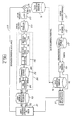
- a spindle-coupled simulator 10 is shown with a computer-implemented system for control thereof.
- the computer-implemented control features a loss-of-contact tyre model 12, which is triggered based upon flags set for desired data, indicated at 14.
- the flags in box 14 are set based upon a desired response 16 obtained from proving ground road tests, as further described below.
- the loss-of-contact control method is implemented on a computer 18 and can be monitored and/or modified by a user 20.
- a summer 22 develops an input 24 from the loss-of-contact models 12 and the desired response 16, and the sum 24 is then input into a control module 26 on a platform 28 of the spindle-coupled simulator 10.
- the spindle-coupled simulator 10 has a simulator controlled apparatus 30 connected at each vehicle spindle 32 after the tyres of a vehicle 34 have been removed.
- the spindle-coupled simulator 10 can introduce from three to five forces and moments at each vehicle speed spindle 32 so as to comprehensively test the complete vehicle for structural durability, except for internal powertrain components.
- An achieved response 36 from the spindle-coupled simulator 10 is input to the loss-of-contact model 12 to complete the loop.
- FIG. 2 a flow chart showing a preferred embodiment of the method of the present invention is shown.
- a vehicle A indicated at 40, is driven over a test road at proving ground facilities, indicated at 42.
- Spindle dynamics data at 44 is collected and used with an inverse tyre model, indicated at 46, to develop a generic effective road profile, or desired response, 16.
- an effective road profile flag is set for a vertical and longitudinal component of the tyre position, as indicated in box 14 and further discussed below.
- Vehicle B which has a different configuration than that of Vehicle A, is coupled to the spindle-coupled simulator 10.
- a servo-controller 48 such as a conventional servo-control apparatus, is used for control of the road simulator.
- System modelling of the Vehicle B, the road simulator 10, and the servo-controller 48 collectively comprise a transfer function HB, indicated generally at 50.
- Spindle dynamics data for Vehicle B, indicated at cylinder 52, are generated from the road simulator 10 with Vehicle B attached thereto.
- the spindle dynamics data 52 is then used in conjunction with the inverse tyre model 54 for Vehicle B to yield and an achieved response 56.
- the transfer function HB, the spindle dynamics 52, and the inverse tyre model 54 collectively comprise a transfer function HBT, indicated generally at 58.
- a signal 36 representing the achieved response 56 is then used in conjunction with the loss-of-contact models 12, further discussed below, to produce a composite feedback 60.
- a sum between the desired response 16 and the composite feedback 60 is calculated at the summer 62 and is operated on by an inverse transfer function HBT 1 , indicated at 64, before being written to a drive file B, indicated generally at cylinder 66.
- the set of control signals thus generated in the drive file B represents a unique control input for a particular simulator-vehicle-controller combination.
- the Vehicle B can then be further tested while coupled to the spindle-coupled simulator without the need for driving it over the test road.
- a "road event” resulting in tyre loss-of-contact with a road surface is shown in graphical form.
- Such an event may be representative of, for example, a bump or other obstruction in the road surface which causes a vehicle tyre to temporarily depart from the surface.
- the road event can be separated into five sections, including a pre-impact role section 80, a bump impact section 82, a hub section 84, a road impact section 86, and a post-impact role section 88.
- Those skilled in the art will recognise that the road event graphically depicted in Fig. 3 is but one of many road events for which the loss-of-contact method and system described herein is applicable.
- the horizontal access of the graph is longitudinal travel, in the x-direction, while the vertical access represents vertical vehicle spindle displacement, in the z-direction.
- a vertical tyre deflection graph is shown separated into road event sections corresponding to those described above with reference to Fig. 3 .
- the horizontal access corresponds to longitudinal vehicle travel, and the vertical access is a computed vertical tyre deflection.
- the vertical tyre deflection is normally in compression during pre-impact and post-impact role sections of a road event. This compression is due to vehicle weight on the tyres.
- sections 82 and 86 of Fig. 3 the vertical tyre deflection is in greater compression than during the role sections 80 and 88, respectively.
- the hop section 84 is of particular interest, since during that section of the road event, the vertical tyre deflection is zero since the vehicle mass is no longer loading the tyre against the road surface. That is, the tyre is no longer in contact with the road surface.
- This vertical effective tyre profile can, for the most part, be used as the effective road profile when the net vertical deflection is greater than zero. During those periods, an effective road profile flag is set equal to one. However, when the net tyre deflection is less than or equal to zero, the effective road profile in the vertical direction is undefined since the vehicle tyre is no longer in contact with the road surface. During that time, the effective road profile flag is set equal to zero, as seen in Fig. 4C .
- flags are used a shown in box 14 of Fig. 2 to select a signal for an effective tyre profile air, or composite feedback 60, between a generated output from the control loop representing a tyre in contact with the road surface and a tyre deflection representing a tyre having lost contact with the road surface.
- ETP error ETP desired * ERP - FLAG desired * ERP - FLAG achieved desired response - ETP achieved * ERP - FLAG desired * ERP - FLAG achieved composite tracking response - ⁇ Tv * 1 - ERP - FLAG achieved ,
- ETP desired the effective tyre profile from the desired response in cylinder 16 of Fig. 2
- ETP achieved the effective tyre profile from the achieved response of the dynamic test in cylinder 56 of Fig. 2
- ERP-FLAG desired the effective road profile flag, as described above, for the desired response
- ERP-FLAG desired the effective road profile flag as described above for the achieved response.
- this loss-of-contact model is to determine a composite response error for an effective tyre profile using the difference between the desired and the desired achieved tyre profiles as an input to the feedback control loop of Fig. 2 where both the desired and achieved effective road profiles are defined, that is, where the tyre is in contact with the road surface.
- the desired effective road profile is not defined, that is, where the ERP-FLAG desired is zero, no error exists unless tyre extension is predicted, that is, the achieved response (cylinder 56 of Fig.
- ETP error is equal to the tyre deflection ( ⁇ T v ), and the feedback control loop will eventually remove the tyre extension error.
- An effective road profile graph shown in Fig. 5C , is developed base upon the absolute value of the net longitudinal tyre deflection. If the absolute value of the net longitudinal tyre deflection is greater than a predetermined threshold value, then the effective road profile in the longitudinal direction (ERP L ) is set equal to the effective tyre profile in the longitudinal direction (ETP L ) . However, if the absolute value of the net longitudinal tyre deflection is less than the predetermined threshold, then the effective road profile in the longitudinal direction is undefined, and an effective road profile flag for the longitudinal direction is set equal to zero.
- ETP longerror ETP desired * ERP - FLAG desired desired response - ETP achieved * ERP - FLAG desired composite tracking response - ⁇ Tl * 1 - ERP - FLAG achieved ,
- a longitudinal effective tyre profile error is set equal to the difference between a predetermined longitudinal effective tyre profile and a longitudinal component of the generated output form the feedback control loop. That is, if a loss-of-contact condition has not been flagged for the predetermined longitudinal effective tyre profile, the longitudinal effective tyre profile error, or component longitudinal error, is the difference between the desired longitudinal effective tyre profile and the achieved longitudinal effective tyre profile. However, where a loss-of-contact condition is flagged, the longitudinal input error is set equal to a feedback loop longitudinal tyre deflection, that is, ⁇ Tl .
- a flagged condition essentially corresponds to a situation where the vehicle is modelled as a free transient response.
- a first tyre model is developed for a first vehicle, and a tyre profile is estimated for a road surface over which the first vehicle was driven.
- An estimate of the tyre profile is made based upon a set of spindle dynamics data for the first vehicle and the first tyre model.
- a second tyre model is then developed for a second vehicle, and the second vehicle is then coupled to a spindle-coupled simulator.
- a set of control signals is generated in a feedback control loop for driving the spindle-coupled simulator with the second vehicle attached thereto so that a response generated by the spindle-coupled simulator is consistent with the estimated tyre profile.
- the set of control signals is generated by selecting a signal for an effective tyre profile error, or composite error, from a generated output from the control loop representing a tyre in contact with the road surface and a tyre deflection representing a tyre having lost contact with the road surface.
- the feedback control loop has an input formed by the difference between the predetermined effective tyre profile and the effective tyre profile error from the feedback control loop.
- a loss-of-contact condition in the predetermined tyre deflection profile is flagged by determining if a dynamic tyre deflection exceeds a pre-load tyre deflection. If a loss-of-contact condition is flagged, a tyre deflection is calculated for use as the defective tyre profile error in the feedback control loop during simulation with the second vehicle coupled to the spindle-coupled simulator.
- a loss-of-contact condition can be dynamically flagged for the response generated by the spindle-coupled simulator with the second vehicle attached thereto.
- the input error in the feedback control loop is comprised of a vertical input error and a longitudinal input error.
- the vertical input error is set equal to the difference between a predetermined vertical effective tyre profile and the generated output from the feedback control loop if a loss-of-contact condition has not been flagged for either signal, setting the input error to zero where both of the signals have been flagged, and setting the input error to a feedback loop vertical tyre deflection if only the generated output from the feedback control loop has been flagged.
- the longitudinal input error is set equal to the distance between a predetermined longitudinal effective tyre profile and a longitudinal component of the generated output from the control feedback loop if a loss-of-contact condition has not been flagged for the predetermined longitudinal effective tyre profile.
- the longitudinal input error is set equal to a feedback loop longitudinal tyre deflection if the predetermined longitudinal effective tyre profile has been flagged.
Landscapes
- Physics & Mathematics (AREA)
- General Physics & Mathematics (AREA)
- Tires In General (AREA)
- Vehicle Body Suspensions (AREA)
- Feedback Control In General (AREA)
Claims (9)
- Procédé de contrôle ou de commande d'un simulateur de route d'un véhicule automobile à couplage axial, avec un profil de pneu efficace ou effectif prédéterminé pour une surface routière, le procédé comprenant les étapes consistant à :développer un modèle de pneu pour un véhicule ;coupler ledit véhicule avec ledit simulateur à couplage axial; etproduire un ensemble de signaux de contrôle ou de commande dans une boucle de contrôle ou de commande de retour pour entraîner ledit simulateur à couplage axial avec ledit véhicule auquel il est couplé ou attaché, de sorte qu'une réponse produite par ledit simulateur à couplage axial soit cohérente avec ledit profil de pneu efficace ou effectif prédéterminé ;
caractérisé par l'étape consistant àsélectionner un signal pour une erreur de profil de pneu efficace ou effectif à partir d'une sortie produite provenant de la boucle de contrôle ou de commande de retour, qui représente un pneu en contact avec la surface routière, et une déformation ou une déviation de pneu représentant un pneu ayant perdu le contact avec la surface routière. - Procédé de contrôle d'un simulateur de route d'un véhicule automobile à couplage axial comprenant les étapes consistant à :développer un premier modèle de pneu pour un premier véhicule ;estimer un profil de pneu pour une surface routière sur laquelle ledit premier véhicule a été conduit, à partir d'un ensemble de données dynamiques d'axe pour ledit premier véhicule et ledit premier modèle de pneu ;développer un deuxième modèle de pneu pour un deuxième véhicule ;coupler ledit deuxième véhicule audit simulateur à couplage axial ; etproduire un ensemble de signaux de contrôle ou de commande dans une boucle de contrôle ou de commande de retour pour entraîner ledit simulateur à couplage axial avec ledit deuxième véhicule auquel il est couplé ou attaché, de sorte qu'une réponse produite par ledit simulateur à couplage axial soit cohérente avec ledit profil de pneu estimé ;
caractérisé en ce queledit ensemble de signaux de contrôle ou de commande est produit en sélectionnant un signal pour une erreur de profil de pneu efficace ou effectif à partir d'une sortie produite provenant de la boucle de contrôle ou de commande, représentant un pneu en contact avec la surface routière, et une déformation ou une déviation de pneu qui représente un pneu ayant perdu le contact avec la surface routière. - Procédé selon la revendication 1 ou 2, dans lequel ladite boucle de contrôle ou de commande de retour possède une entrée formée par la différence entre le profil de pneu efficace ou effectif prédéterminé et l'erreur de profil de pneu efficace ou effectif provenant de la boucle de contrôle ou de commande de retour.
- Procédé selon la revendication 1 ou 2, comprenant l'étape consistant à indiquer un état ou une condition de perte de contact dans ledit profil de déformation ou de déviation de pneu prédéterminé, en déterminant si une déformation ou une déviation de pneu dynamique excède une déformation ou une déviation de pneu en pré - charge, et en calculant une déformation ou déviation de pneu pour utilisation en tant qu'erreur de profil de pneu efficace ou effectif dans la boucle de contrôle ou de commande de retour lorsqu'un état ou une condition de perte de contact est indiqué ou indiquée.
- Procédé selon la revendication 4, comprenant l'étape consistant à indiquer un état ou une condition de perte de contact dans la réponse produite par le simulateur à couplage axial.
- Procédé selon la revendication 5, dans lequel l'erreur en entrée consiste en une erreur en entrée verticale et une erreur en entrée longitudinale.
- Procédé selon la revendication 6, comprenant l'étape consistant à régler l'erreur en entrée verticale au niveau de la différence entre un profil de pneu efficace ou effectif vertical prédéterminé et la sortie produite provenant de la boucle de contrôle ou de commande de retour si un état ou une condition de perte de contact n'a été indiqué ou indiquée ni pour un signal ni pour l'autre, régler l'erreur en entrée à zéro lorsque ou où les deux signaux ont été indiqués, et régler l'erreur en entrée au niveau d'une déformation ou déviation de pneu verticale de boucle de contrôle ou de commande si seule la sortie produite provenant de la boucle de contrôle ou de commande de retour a été indiquée.
- Procédé selon la revendication 6, comprenant l'étape consistant à régler l'erreur en entrée longitudinale au niveau de la différence entre un profil de pneu efficace ou effectif longitudinal prédéterminé et une composante longitudinale de la sortie produite provenant de la boucle de contrôle ou de commande de retour si un état ou une condition de perte de contact n'a pas été indiqué pour le profil de pneu efficace ou effectif longitudinal prédéterminé, et régler l'erreur en entrée longitudinale au niveau d'une déformation ou déflection de pneu longitudinale de boucle de contrôle ou de commande si le profil de pneu efficace longitudinal prédéterminé a été indiqué.
- Système pour simuler un essai routier d'un véhicule automobile, le système comprenant :un simulateur à couplage axial adapté pour recevoir sur lui le véhicule ;un moyen de mémoire électronique pour enregistrer un ensemble de données, représentant une réponse souhaitée provenant d'un véhicule source qui a été conduit sur une surface routière ; etun moyen de boucle de contrôle ou de commande de retour pour entraîner le simulateur à couplage axial,
caractérisé parun moyen à code de perte de contact pour sélectionner un signal de retour parmi une sortie produite provenant du simulateur à couplage axial, représentant un pneu en contact avec la surface routière, et une déformation ou déviation de pneu qui représente un pneu ayant perdu contact avec la surface routière.
Applications Claiming Priority (2)
| Application Number | Priority Date | Filing Date | Title |
|---|---|---|---|
| US146390 | 1993-11-01 | ||
| US09/146,390 US6112586A (en) | 1998-08-31 | 1998-08-31 | Effective road profile simulation method and system with tires loss-of-contact compensation |
Publications (3)
| Publication Number | Publication Date |
|---|---|
| EP0984261A2 EP0984261A2 (fr) | 2000-03-08 |
| EP0984261A3 EP0984261A3 (fr) | 2001-08-08 |
| EP0984261B1 true EP0984261B1 (fr) | 2009-08-12 |
Family
ID=22517152
Family Applications (1)
| Application Number | Title | Priority Date | Filing Date |
|---|---|---|---|
| EP99306798A Expired - Lifetime EP0984261B1 (fr) | 1998-08-31 | 1999-08-27 | Méthode de simulation effective du profile de route et système de compensation de perte de contacte des roues |
Country Status (4)
| Country | Link |
|---|---|
| US (1) | US6112586A (fr) |
| EP (1) | EP0984261B1 (fr) |
| JP (1) | JP2000074793A (fr) |
| DE (1) | DE69941244D1 (fr) |
Families Citing this family (12)
| Publication number | Priority date | Publication date | Assignee | Title |
|---|---|---|---|---|
| DE102005022096A1 (de) * | 2005-05-12 | 2006-11-16 | Fraunhofer-Gesellschaft zur Förderung der angewandten Forschung e.V. | Vorrichtung und Verfahren zur vibroakustischen Untersuchung eines Kraftfahrzeuges |
| US7363805B2 (en) * | 2005-09-30 | 2008-04-29 | Ford Motor Company | System for virtual prediction of road loads |
| US7194888B1 (en) * | 2006-04-10 | 2007-03-27 | Daimlerchrysler Corporation | Reducing drive file development time for a vehicle road test simulator |
| DE102006057342A1 (de) * | 2006-12-05 | 2008-06-12 | Siemens Ag | Verfahren zum Ermitteln eines Fahrbahnzustands |
| CN103175678B (zh) * | 2011-12-23 | 2015-09-16 | 华锐风电科技(集团)股份有限公司 | 加载试验台 |
| JP6121521B2 (ja) | 2012-04-11 | 2017-04-26 | ブリヂストン アメリカズ タイヤ オペレイションズ エルエルシー | 転動タイヤの定常状態シミュレーションのためのシステムおよび方法 |
| FR3071064A1 (fr) * | 2017-09-14 | 2019-03-15 | Compagnie Generale Des Etablissements Michelin | Methode d'evaluation de la fermete d'un sol |
| CN108844734A (zh) * | 2018-06-13 | 2018-11-20 | 柳州北斗星液压科技有限公司 | 轴耦合式底盘传动性能测试装置 |
| CN108760338B (zh) * | 2018-06-22 | 2020-07-31 | 天津英创汇智汽车技术有限公司 | 无人驾驶在环测试装置及系统 |
| CN110296853A (zh) * | 2019-05-17 | 2019-10-01 | 重庆长安汽车股份有限公司 | 一种汽车悬架系统疲劳试验台 |
| CN112817335B (zh) * | 2021-01-29 | 2021-10-01 | 北京信息科技大学 | 激光驾束制导飞行器的制导控制方法 |
| CN112924198B (zh) * | 2021-04-01 | 2025-06-17 | 中信戴卡股份有限公司 | 一种用于汽车底盘模拟路试的加载系统及试验设备 |
Family Cites Families (8)
| Publication number | Priority date | Publication date | Assignee | Title |
|---|---|---|---|---|
| US3718033A (en) * | 1971-04-20 | 1973-02-27 | Mts System Corp | Testing apparatus utilizing position-force cross coupling control |
| US5003819A (en) * | 1990-01-02 | 1991-04-02 | Bridgestone/Firestone, Inc. | Suspension simulator |
| US4981034A (en) * | 1990-05-01 | 1991-01-01 | Mts Systems Corporation | Tire emulator for road simulators |
| US5065618A (en) * | 1990-11-14 | 1991-11-19 | Hodges Transportation Inc. | Method and apparatus for determining terrain surface profiles |
| US5533403A (en) * | 1994-11-10 | 1996-07-09 | Mts Systems Corporation | Loading assembly for a vehicle spindle test fixture |
| US5610330A (en) * | 1996-01-16 | 1997-03-11 | Ford Motor Company | Effective road profile control method for a spindle-coupled road simulator |
| US5900542A (en) * | 1996-04-15 | 1999-05-04 | Ford Global Technologies, Inc. | Method and apparatus for modelling a tire for use with a vehicle spindle-coupled simulator |
| JPH11173952A (ja) * | 1997-12-10 | 1999-07-02 | T & T:Kk | タイヤ試験装置 |
-
1998
- 1998-08-31 US US09/146,390 patent/US6112586A/en not_active Expired - Lifetime
-
1999
- 1999-08-27 EP EP99306798A patent/EP0984261B1/fr not_active Expired - Lifetime
- 1999-08-27 DE DE69941244T patent/DE69941244D1/de not_active Expired - Lifetime
- 1999-08-30 JP JP11243012A patent/JP2000074793A/ja active Pending
Also Published As
| Publication number | Publication date |
|---|---|
| EP0984261A2 (fr) | 2000-03-08 |
| DE69941244D1 (de) | 2009-09-24 |
| JP2000074793A (ja) | 2000-03-14 |
| EP0984261A3 (fr) | 2001-08-08 |
| US6112586A (en) | 2000-09-05 |
Similar Documents
| Publication | Publication Date | Title |
|---|---|---|
| US5610330A (en) | Effective road profile control method for a spindle-coupled road simulator | |
| EP0984261B1 (fr) | Méthode de simulation effective du profile de route et système de compensation de perte de contacte des roues | |
| US5877414A (en) | Vehicle road load simulation using effective road profile | |
| Dodds et al. | Laboratory road simulation for full vehicle testing: a review | |
| US10956636B2 (en) | Method for optimizing the construction of a car body | |
| Cheng et al. | Experiences in reverse-engineering of a finite element automobile crash model | |
| US6134957A (en) | Multiple degree-of-freedom tire modeling method and system for use with a vehicle spindle-coupled simulator | |
| Rauh | Virtual development of ride and handling characteristics for advanced passenger cars | |
| WO1997021087A1 (fr) | Tests par vibrations sinusoidales permettant de verifier la durabilite d'un produit | |
| US6711476B2 (en) | Method and computer program product for estimating at least one state of a dynamic system | |
| CA2217151C (fr) | Methode et appareil de modelisation de pneumatique pour simulateur de route a couplage chaussee-fusee d'essieu | |
| Garrott et al. | Methodology for validating the national advanced driving simulator's vehicle dynamics (NADSdyna) | |
| US5750890A (en) | Method and apparatus for modelling a tire for use with a vehicle spindle-coupled simulator | |
| Kersten et al. | Study to assess the controllability after chassis component damages on the dynamic driving simulator | |
| Clijmans et al. | Structural modification effects on the dynamic behavior of an agricultural tractor | |
| KR20250071210A (ko) | 결합형 하이브리드 동적 시스템을 테스트하기 위한 방법 및 시스템 | |
| Jurisch et al. | Simulation-Based Development for Active Suspension Control for Automated Driving Vehicles—Evaluation of Transferability to Real-World Testing | |
| Wirje et al. | Modeling and Simulation of Peak Load Events Using Adams-Driving Over a Curb and Skid Against a Curb | |
| JP2004245691A (ja) | 地震応答解析方法 | |
| JP7198942B2 (ja) | Wimセンサーのための較正及びサイト選択、並びにwimセンサー | |
| Wagner et al. | Simplified model for self-excited rear-axlevibrations | |
| JP3002154B2 (ja) | 自動大型走行機器設計システム | |
| Schramm et al. | Model of a typical complex complete vehicle | |
| Szurgott et al. | Dynamic Interaction Between Heavy Vehicles And Speed Bumps. | |
| Hickson | Design and development of an active roll control suspension |
Legal Events
| Date | Code | Title | Description |
|---|---|---|---|
| PUAI | Public reference made under article 153(3) epc to a published international application that has entered the european phase |
Free format text: ORIGINAL CODE: 0009012 |
|
| AK | Designated contracting states |
Kind code of ref document: A2 Designated state(s): BE DE FR GB |
|
| AX | Request for extension of the european patent |
Free format text: AL;LT;LV;MK;RO;SI |
|
| PUAL | Search report despatched |
Free format text: ORIGINAL CODE: 0009013 |
|
| AK | Designated contracting states |
Kind code of ref document: A3 Designated state(s): AT BE CH CY DE DK ES FI FR GB GR IE IT LI LU MC NL PT SE |
|
| AX | Request for extension of the european patent |
Free format text: AL;LT;LV;MK;RO;SI |
|
| 17P | Request for examination filed |
Effective date: 20011231 |
|
| AKX | Designation fees paid |
Free format text: BE DE FR GB |
|
| 17Q | First examination report despatched |
Effective date: 20080414 |
|
| GRAP | Despatch of communication of intention to grant a patent |
Free format text: ORIGINAL CODE: EPIDOSNIGR1 |
|
| GRAS | Grant fee paid |
Free format text: ORIGINAL CODE: EPIDOSNIGR3 |
|
| GRAA | (expected) grant |
Free format text: ORIGINAL CODE: 0009210 |
|
| AK | Designated contracting states |
Kind code of ref document: B1 Designated state(s): BE DE FR GB |
|
| REG | Reference to a national code |
Ref country code: GB Ref legal event code: FG4D |
|
| REF | Corresponds to: |
Ref document number: 69941244 Country of ref document: DE Date of ref document: 20090924 Kind code of ref document: P |
|
| PLBE | No opposition filed within time limit |
Free format text: ORIGINAL CODE: 0009261 |
|
| STAA | Information on the status of an ep patent application or granted ep patent |
Free format text: STATUS: NO OPPOSITION FILED WITHIN TIME LIMIT |
|
| 26N | No opposition filed |
Effective date: 20100517 |
|
| REG | Reference to a national code |
Ref country code: DE Ref legal event code: R082 Ref document number: 69941244 Country of ref document: DE Representative=s name: DOERFLER, THOMAS, DR.-ING., DE |
|
| REG | Reference to a national code |
Ref country code: FR Ref legal event code: PLFP Year of fee payment: 18 |
|
| REG | Reference to a national code |
Ref country code: FR Ref legal event code: PLFP Year of fee payment: 19 |
|
| PGFP | Annual fee paid to national office [announced via postgrant information from national office to epo] |
Ref country code: DE Payment date: 20170825 Year of fee payment: 19 Ref country code: FR Payment date: 20170720 Year of fee payment: 19 Ref country code: GB Payment date: 20170725 Year of fee payment: 19 |
|
| PGFP | Annual fee paid to national office [announced via postgrant information from national office to epo] |
Ref country code: BE Payment date: 20170818 Year of fee payment: 19 |
|
| REG | Reference to a national code |
Ref country code: DE Ref legal event code: R119 Ref document number: 69941244 Country of ref document: DE |
|
| GBPC | Gb: european patent ceased through non-payment of renewal fee |
Effective date: 20180827 |
|
| REG | Reference to a national code |
Ref country code: BE Ref legal event code: MM Effective date: 20180831 |
|
| PG25 | Lapsed in a contracting state [announced via postgrant information from national office to epo] |
Ref country code: DE Free format text: LAPSE BECAUSE OF NON-PAYMENT OF DUE FEES Effective date: 20190301 |
|
| PG25 | Lapsed in a contracting state [announced via postgrant information from national office to epo] |
Ref country code: FR Free format text: LAPSE BECAUSE OF NON-PAYMENT OF DUE FEES Effective date: 20180831 Ref country code: BE Free format text: LAPSE BECAUSE OF NON-PAYMENT OF DUE FEES Effective date: 20180831 |
|
| PG25 | Lapsed in a contracting state [announced via postgrant information from national office to epo] |
Ref country code: GB Free format text: LAPSE BECAUSE OF NON-PAYMENT OF DUE FEES Effective date: 20180827 |