EP0984292B1 - Srommessung in Pumpen - Google Patents
Srommessung in Pumpen Download PDFInfo
- Publication number
- EP0984292B1 EP0984292B1 EP99116944A EP99116944A EP0984292B1 EP 0984292 B1 EP0984292 B1 EP 0984292B1 EP 99116944 A EP99116944 A EP 99116944A EP 99116944 A EP99116944 A EP 99116944A EP 0984292 B1 EP0984292 B1 EP 0984292B1
- Authority
- EP
- European Patent Office
- Prior art keywords
- pump
- resistance
- control electronics
- supply line
- conductive portion
- Prior art date
- Legal status (The legal status is an assumption and is not a legal conclusion. Google has not performed a legal analysis and makes no representation as to the accuracy of the status listed.)
- Expired - Lifetime
Links
Images

Classifications
-
- G—PHYSICS
- G01—MEASURING; TESTING
- G01R—MEASURING ELECTRIC VARIABLES; MEASURING MAGNETIC VARIABLES
- G01R19/00—Arrangements for measuring currents or voltages or for indicating presence or sign thereof
- G01R19/0092—Measuring current only
-
- G—PHYSICS
- G01—MEASURING; TESTING
- G01R—MEASURING ELECTRIC VARIABLES; MEASURING MAGNETIC VARIABLES
- G01R1/00—Details of instruments or arrangements of the types included in groups G01R5/00 - G01R13/00 and G01R31/00
- G01R1/20—Modifications of basic electric elements for use in electric measuring instruments; Structural combinations of such elements with such instruments
- G01R1/203—Resistors used for electric measuring, e.g. decade resistors standards, resistors for comparators, series resistors, shunts
-
- G—PHYSICS
- G01—MEASURING; TESTING
- G01R—MEASURING ELECTRIC VARIABLES; MEASURING MAGNETIC VARIABLES
- G01R31/00—Arrangements for testing electric properties; Arrangements for locating electric faults; Arrangements for electrical testing characterised by what is being tested not provided for elsewhere
- G01R31/34—Testing dynamo-electric machines
- G01R31/343—Testing dynamo-electric machines in operation
Definitions
- the invention relates to a method for determining the current consumption of a controlled by an electronic control pump by measuring the voltage drop across a resistor element located in the pump.
- the invention also relates to a pump which is suitable for carrying out the method.
- German Patent Application DE 195 37 495 discloses a device for monitoring the current consumption of an electrical load, for example a motor, in whose supply cable a fuse is inserted, which acts as a resistance element, at which the occurring voltage drop when current is applied to the motor tapped by a measuring circuit and From this, the current consumption of the electrical load is determined.
- the function of electric motors, in particular pumps, such as electronically controlled centrifugal pumps, can be monitored by measuring operating parameters, such as the current consumed by the motor. In this case, an increase in the current flow indicates a higher load on the pump, so that, for example, an overload can be detected and the pump can be switched off in the manner of an emergency stop.
- a current measurement also offers the possibility to regulate the speed of the pump.
- Such a method is known for example from German Utility Model DE 90 13 486.9 U1, which has the power control of an electric motor in a high-pressure cleaning device to the object.
- the power control makes use of the physical relationship that the pressure of the fluid delivered by the pump is directly proportional to the torque of the motor, which in turn is directly proportional to the absorbed current of the motor.
- the absorbed current of the electric motor is therefore used in the control as a direct measure of the output pressure of the pump.
- the current measurement is measured as a voltage drop over a defined resistance.
- a measuring resistor is arranged within the power electronics.
- Such a measuring resistor has the disadvantage that it represents an extra component, which as such causes additional costs and must also be soldered in a separate step in the manufacturing process.
- the expenses for the measuring resistor and its installation play a serious role.
- the measuring resistor consumes power, which on the one hand contributes to the unwanted heating of the electronics and on the other hand in continuous operation of the pump as a cost factor for the customer and weighted him with a higher electricity bill.
- US Pat. No. 4,584,525 discloses a device for measuring the current flowing in a line, in which the copper line within the electrical conductor itself serves as the resistance element.
- the device here comprises two pointed measuring tips which are connected to one another are spaced and pushed through the insulating plastic sheath of the electrical conductor to contact the inner metallic conductor. It is thus a universal, on many types of conductors, such as copper or aluminum, any diameter applicable current measuring device provided, which can be used for example in a hand-held device. With the help of switches, the measuring range can be adjusted depending on the selected electrical conductor.
- the object of the invention is therefore to provide a method for current measurement, which contributes to high accuracy of the measurement results to simplify the pump and thus to minimize the manufacturing and operating costs of the pump. At the same time it is an object of the invention to provide a pump suitable for the application of the method.
- the inventive method uses a piece of a connecting line between the control electronics and the supply voltage and no Medlötendes in the pump separate component (measuring resistor) for the measurement of the current, manufacturing costs are initially saved. With a small heating pump this can be a savings of about 2.0%, if you do without the extra resistance and instead use a piece of the existing connection wire. It is self-evident that the resistance of the wire piece used for the measurement is known. The use of the Connecting wire makes the installation of the measuring resistor superfluous and thus simplifies the production.
- the reliability of the measurement and thus the reliability of the pump is increased insofar as to dispense with a component that can represent a source of error.
- the waiver of the measuring resistor means beyond the waiver of an unnecessary consumer, which loads the efficiency of the pump and contributes to unwanted heating of the pump or the electronics.
- the space of the electronics and thus the dimensions of the pump can be reduced, which is particularly in view of the use of the pump in confined areas of great advantage.
- the minimization of the installation space makes the method according to the invention particularly advantageous for small pumps such as centrifugal pumps, in particular for use in heating circuits.
- a particularly accurate current measurement is possible if a computing unit, e.g. the microcomputer present in the control electronics effects the calculation of the power consumption from the value of the voltage drop across the length of the connecting line.
- a microcomputer calculates in a particularly simple manner the current absorbed by the pump from the value of the current absorbed by the control unit. It is advantageous to consider disturbing factors, such as the temperature behavior of the connecting line or the influences of the control electronics on the voltage drop separately and included in the calculation. The consideration of such disturbances is essential insofar as according to the inventive method, the power consumption of the pump, which essentially corresponds to the power consumption of the power electronics, from the comparatively small current flowing in the control electronics, "indirectly" is determined.
- the piece of the connecting line made of wire, defined as resistance element is made of a defined resistor, in particular of so-called resistance wire, which is distinguished by a known specific resistance.
- This resistance wire only needs to be cut to a certain length and installed in the pump.
- Resistance wire within a temperature range shows a predictable behavior, its characteristics of the computing unit can be provided as a record or as a functional dependency and so easily taken into account in the calculation of the current.
- the conductor piece is applied by bonding between a plug contact, to which the supply voltage is applied, and a printed circuit board of the control electronics.
- Wire advantageously has a resistance of about 1-5 milliohms.
- FIG. 1 a shows a per se known centrifugal pump 1 for a heating water circuit with inlet 2 and outlet 3.
- the pump 1 has an electric motor in a motor housing 4, which drives a pump impeller located in the housing 5.
- the terminal box 6 includes both the connections for the power electronics 7 and the control electronics 8 ( Figure 3).
- Figure 1b shows a centrifugal pump without terminal box with a direct connection 18 on the motor housing 4.
- the electronics is installed in this case in an axially behind the motor housing 4 patch box 19, to which a plug 20 is formed for connecting the supply voltage.
- the electronic components 21 are applied to a substrate made of ceramic or a printed circuit board 22.
- the connection from the printed circuit board 22 to the plug 20 takes place via a bonding wire 23.
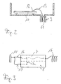
- the embodiment of Figure 2 shows a section through the terminal box 6, which can be placed with a foot 9 on the housing of the motor 4 is.
- a circuit board 10 of the control electronics is housed in the terminal box 6, in the terminal box 6, a circuit board 10 of the control electronics is housed.
- the board 10 is connected via a plug contact 11 with the windings of the motor 4.
- a wire 13 Between the plug contact 11 and the terminal contact 12 of the board 10 is a wire 13, which is applied by the method of bonding, the contact forth.
- the bonding wire 13 in this case has a resistance of 2-3 milliohms and is used as a measuring resistor for the current measurement.
- FIG. 3 shows the circuit diagram for current measurement in a pump.
- the power electronics 7 is supplied via a supply line 16 with power.
- the winding 16 is connected (broken line).
Landscapes
- Physics & Mathematics (AREA)
- General Physics & Mathematics (AREA)
- Control Of Non-Positive-Displacement Pumps (AREA)
- Structures Of Non-Positive Displacement Pumps (AREA)
- Control Of Positive-Displacement Pumps (AREA)
Description
- Die Erfindung betrifft ein Verfahren zur Bestimmung der Stromaufnahme einer mittels einer Steuerelektronik geregelten Pumpe durch Messung des Spannungsabfalls über einem in der Pumpe befindlichen Widerstandselement. Die Erfindung betrifft zudem eine Pumpe, die zur Durchführung des Verfahrens geeignet ist.
- Derartige Verfahren sind bekannt. Beispielsweise offenbart die deutsche Offenlegungsschrift DE 195 37 495 eine Vorrichtung zur Überwachung der Stromaufnahme eines elektrischen Verbrauchers, beispielsweise eines Motors, in dessen Zuleitungskabel eine Schmelzsicherung eingebracht ist, welche als Widerstandselement fungiert, an dem der auftretende Spannungsabfall bei Bestromung des Motors durch eine Messschaltung abgegriffen und daraus die Stromaufnahme des elektrischen Verbrauchers ermittelt wird.
- Die Funktion von Elektromotoren insbesondere von Pumpen, wie z.B. von elektronisch geregelten Kreiselpumpen, kann durch die Messung von Betriebsparametern wie des Stromes, den der Motor aufnimmt, überwacht werden. Dabei deutet eine Erhöhung des Stromflusses auf eine höhere Belastung der Pumpe hin, so dass beispielsweise eine Überlastung festgestellt und die Pumpe nach Art eines Notstopps abgeschaltet werden kann. Neben dieser Schutzfunktion bietet eine Strommessung darüberhinaus die Möglichkeit, die Drehzahl der Pumpe zu regeln.
- Ein derartiges Verfahren ist beispielsweise aus dem deutschen Gebrauchsmuster DE 90 13 486.9 U1 bekannt, welches die Leistungsregelung eines Elektromotors bei einem Hochdruckreinigungsgerät zum Gegenstand hat. Die Leistungsregelung macht sich hierbei den physikalischen Zusammenhang zu nutze, dass der Druck der von der Pumpe abgegebenen Flüssigkeit direkt proportional zum Drehmoment des Motors ist, welches wiederum direkt proportional zum aufgenommenen Strom des Motors ist. Der aufgenommene Strom des Elektromotors dient daher bei der Regelung als direktes Maß für den Ausgangsdruck der Pumpe. Durch die Messung der Stromaufnahme des antreibenden Elektromotors, die nicht näher erläutert wird, kann daher eine Regelung des Drucks des Hochdruckreinigers derart erfolgen, dass ein gemessener Istwert mit einem vorgegebenen Sollwert verglichen und aufgrund der Differenz dieser beiden Werte eine regelungstechnische Maßnahme zur Einstellung des gewünschten Solldrucks erfolgt.
- Wie bekannt ist, wird die Strommessung als Spannungsabfall über einem definierten Wiederstand gemessen. Im Falle der elektronisch geregelten Pumpen ist ein solcher Messwiderstand innerhalb der Leistungselektronik angeordnet. Ein solcher Messwiderstand hat den Nachteil, dass er ein extra Bauteil darstellt, welches als solches zusätzliche Kosten verursacht und zudem in einem separaten Schritt im Fertigungsprozeß eingelötet werden muß. Gerade im Hinblich auf die zunehmende Rationalisierung bei der Fertigung immer einfacherer und billigerer Pumpen spielen die Aufwendungen für den Messwiderstand und dessen Einbau eine ernstzunehmende Rolle.
- Weiterhin ist es von Nachteil, dass der Messwiderstand Leistung verbraucht, die einerseits zur unerwünschten Erwärmung der Elektronik beiträgt und die andererseits beim Dauerbetrieb der Pumpe als Kostenfaktor für den Kunden ins Gewicht fällt und ihn mit einer höheren Stromrechnung belastet.
- Aus der amerikanischen Patentschrift US 4,584,525 ist eine Vorrichtung zur Messung des in einer Leitung fließenden Stromes bekannt, bei der als Widerstandselement die Kupferleitung innerhalb des elektrischen Leiters selbst dient. Die Vorrichtung umfasst hier zwei spitze Messspitzen, die zueinander beabstandet sind und durch die isolierende Kunststoffummantelung des elektrischen Leiters gestoßen werden, um den inneren metallischen Leiter zu kontaktieren. Es wird damit eine universale, auf viele Leitertypen, beispielsweise aus Kupfer oder Aluminium, beliebigen Durchmessers anwendbare Strommesseinrichtung bereitgestellt, die beispielsweise in einem Handmessgerät eingesetzt werden kann. Mit Hilfe von Schaltern kann der Messbereich in Abhängigkeit des gewählten elektrischen Leiters eingestellt werden.
- Aufgabe der Erfindung ist es daher, ein Verfahren zur Strommessung zu schaffen, das bei hoher Genauigkeit der Messergebnisse zu einer Vereinfachung der Pumpe und damit zur Minimierung der Herstellungs- und Betriebskosten der Pumpe beiträgt. Gleichzeitig ist es Aufgabe der Erfindung, eine für die Anwendung des Verfahrens geeignete Pumpe zu schaffen.
- Diese Aufgaben werden durch das Verfahren nach Anspruch 1 und die Pumpe nach Anspruch 3 gelöst.
- Dadurch, dass das erfindungsgemäße Verfahren ein Stück einer Verbindungsleitung zwischen der Steuerelektronik und der Versorgungsspannung und kein in die Pumpe einzulötendes separates Bauteil (Messwiderstand) für die Messung des Stromes nutzt, werden zunächst Herstellungskosten gespart. Bei einer kleinen Heizungspumpe kann es sich dabei durchaus um eine Ersparnis von etwa 2.0% handeln, wenn auf den extra Widerstand verzichtet wird und stattdessen auf ein Stück des sowieso vorhandenen Verbindungsdrahtes zurückgegriffen wird. Dabei ist es selbstverständlich, dass der Widerstand des zur Messung verwendeten Drahtstückchens bekannt ist. Die Verwendung des Verbindungsdrahtes macht den Einbau des Messwiderstandes überflüssig und vereinfacht somit die Herstellung.
- Durch die Verwendung der Verbindungsleitung wird die Zuverlässigkeit der Messung und damit die Zuverlässigkeit der Pumpe insofern erhöht, als dass auf ein Bauteil, das eine Fehlerquelle darstellen kann, verzichtet wird. Der Verzicht auf den Messwiderstand bedeutet darüberhinaus den Verzicht auf einen unnötigen Verbraucher, der den Wirkungsgrad der Pumpe belastet und zur ungewünschten Erwärmung der Pumpe bzw. der Elektronik beiträgt. Gleichzeitig kann der Bauraum der Elektronik und damit die Abmessungen der Pumpe verringert werden, was besonders im Hinblick auf den Einsatz der Pumpe unter beengten Verhältnissen von großem Vorteil ist. Die Minimierung des Bauraumes macht das erfindungsgemäße Verfahren für kleine Pumpen wie Kreiselpumpen insbesondere für den Einsatz in Heizkreisläufen besonders vorteilhaft.
- Eine besonders genaue Strommessung ist möglich, wenn eine Recheneinheit, z.B. der in der Steuerelektronik vorhandene Mikrocomputer die Berechnung des Stromaufnahme aus dem Wert des Spannungsabfalls über dem Stück der Verbindungsleitung bewerkstelligt. Ein solcher Mikrocomputer berechnet auf besonders einfache Weise den von der Pumpe aufgenommenen Strom aus dem Wert des von der Steuereinheit aufgenommenen Stromes. Dabei ist es vorteilhaft, Störfaktoren, wie das Temperaturverhalten der Verbindungsleitung oder die Einflüsse der Steuerelektronik auf den Spannungsabfall gesondert zu berücksichtigen und in die Berechnung mit einzubeziehen. Die Berücksichtigung solcher Störgrößen ist insofern unerläßlich, als nach dem erfindungsgemäßen Verfahren die Stromaufnahme der Pumpe, die im Wesentlichen der Stromaufnahme der Leistungselektronik entspricht, aus dem vergleichsweise kleinen Strom, der in die Steuerelektronik fließt, "indirekt" ermittelt wird.
- Besonders vorteilhaft ist es, wenn das als Widerstandselement verwendete Stück der Verbindungsleitung aus Draht definierten Widerstandes insbesondere aus sogenanntem Widerstandsdraht, der sich durch einen bekannten spezifischen Widerstand auszeichnet, gefertigt ist. Dieser Widerstandsdraht braucht lediglich in bestimmter Länge abgeschnitten und in die Pumpe eingebaut zu werden. Da Widerstandsdraht innerhalb eines Temperaturbereiches ein vorhersehbares Verhalten zeigt, können seine Kenndaten der Recheneinheit als Datensatz oder als funktionale Abhängigkeit zur Verfügung gestellt und so einfach in der Berechnung des Stromes berücksichtigt werden.
- In einer besonders vorteilhaften Ausführungsform wird das Leiterstück durch Bonden zwischen einem Steckkontakt, an dem die Versorgungsspannung anliegt, und einer Leiterplatte der Steuerelektronik aufgebracht. Der so aufgebrachte
- Draht hat vorteilhafterweise einen Widerstand von etwa 1-5 mΩ.
- Eine zur Umsetzung des erfindungsgemäßen Verfahrens geeignete Pumpe ist in den Zeichnungen 1, 2 und 3 dargestellt und wird im folgenden näher beschrieben. Es zeigen
- Figur 1
- eine Kreiselpumpe,
- Figur 2
- einen Bonddraht als Messwiderstand und
- Figur 3
- das Schaltschema zur Strommessung.
- In der Figur 1a ist eine an sich bekannte Kreiselpumpe 1 für einen Heizwasserkreislauf mit Einlass 2 und Auslass 3 gezeigt. Die Pumpe 1 hat einen Elektromotor in einem Motorgehäuse 4, der ein in dem Gehäuse 5 befindliches Pumpenlaufrad antreibt. Der elektrische Anschluss der Pumpe 1 geschieht über einen Klemmenkasten 6, der auf dem Gehäuse des Motors 4 aufsitzt. Der Klemmenkasten 6 beinhaltet sowohl die Anschlüsse für die Leistungselektronik 7 als auch die Steuerelektronik 8 (Figur 3). Figur 1b zeigt eine Kreiselpumpe ohne Klemmenkasten mit einem Direktanschluß 18 am Motorgehäuse 4. Die Elektronik ist in diesem Falle in einem axial hinter dem Motorgehäuse 4 aufgesetzten Kasten 19 eingebaut, an den ein Stecker 20 zum Anschluß der Versorgungsspannung angeformt ist. In dem Kasten 19 sind die elektronischen Bauteile 21 auf einem Substrat aus Keramik oder einer Leiterplatte 22 aufgebracht. Die Verbindung von der Leiterplatte 22 zum Stecker 20 geschieht über einen Bonddraht 23.
- Das Ausführungsbeispiel nach Figur 2 zeigt einen Schnitt durch den Klemmenkasten 6, der mit einem Fuß 9 auf das Gehäuse des Motors 4 aufsetzbar ist. In dem Klemmenkasten 6 ist eine Platine 10 der Steuerelektronik untergebracht. Die Platine 10 ist über einen Steckkontakt 11 mit den Wicklungen des Motors 4 verbunden. Zwischen dem Steckkontakt 11 und dem Anschlußkontakt 12 der Platine 10 stellt ein Draht 13, der durch das Verfahren des Bondens aufgebracht ist, den Kontakt her. Der Bonddraht 13 hat in diesem Fall einen Widerstand von 2-3 Milliohm und wird als Messwiderstand für die Strommessung benutzt.
- Figur 3 zeigt das Schaltschema zur Strommessung in einer Pumpe. Ausgehend von dem Spannungsanschluß 14 wird die Leistungselektronik 7 über eine Versorgungsleitung 16 mit Strom versorgt. An die Leistungselektronik 7 ist die Wicklung 16 angeschlossen (unterbrochene Linie). Zur Steuerelektronik 8 führt eine Versorgungsleitung 17, die in diesem Falle aus Wiederstandsdraht besteht und den Messwiderstand darstellt (alternative Führung s. unterbrochene Linie 17a).
Claims (7)
- Verfahren zur Bestimmung der Stromaufnahme einer mittels einer Steuerelektronik geregelten Pumpe (1), dadurch gekennzeichnet, dass ein Spannungsabfall über einem Stück einer Versorgungsleitung mit definiertem Widerstand zwischen der Steuerelektronik (8) und der Versorgungsspannung von einer Recheneinheit der Steuerelektronik gemessen und daraus die Stromaufnahme berechnet wird.
- Verfahren nach einem der vorherigen Ansprüche, dadurch gekennzeichnet, dass mittels der Recheneinheit das Temperaturverhalten der Versorgungsleitung in die Berechnung der Stromaufnahme der Pumpe (1) einbezogen wird.
- Elektronisch geregelte Pumpe mit einer Steuerelektronik zur Regelung, wobei die Steuerelektronik über eine Versorgungsleitung an eine Versorgungsspannung angeschlossen ist, dadurch gekennzeichnet, dass eine Recheneinheit der Steuerelektronik dazu eingerichtet ist, einen Spannungsabfall über einem Stück der genannten Versorgungsleitung zu messen und hieraus die Stromaufnahme zu berechnen, wobei das Leiterstück der Versorgungsleitung einen definierten Widerstand aufweist.
- Pumpe nach Anspruch 3, dadurch gekennzeichnet, dass das Leiterstück ein Stück Widerstandsdraht mit bekanntem spezifischem Widerstand und definierter Länge ist.
- Pumpe nach Anspruch 3, dadurch gekennzeichnet, dass das Leiterstück (23) ein durch Bonden zwischen einem Steckkontakt, an dem die Versorgungsspannung anliegt, und einer Leiterplatte (19) der Steuerelektronik (8) aufgebrachtes Drahtstück definierten Widerstandes ist.
- Pumpe nach einem der Ansprüche 3 bis 5, dadurch gekennzeichnet, dass der Widerstand des Leiterstückes zwischen 1 und 5 mΩ beträgt.
- Pumpe nach einem der Ansprüche 3 bis 6, dadurch gekennzeichnet, dass die Abhängigkeit des Widerstands des Leiterstückes von der Temperatur der Recheneinheit zur Verfügung stehen.
Applications Claiming Priority (2)
| Application Number | Priority Date | Filing Date | Title |
|---|---|---|---|
| DE19840479 | 1998-09-04 | ||
| DE19840479A DE19840479A1 (de) | 1998-09-04 | 1998-09-04 | Strommessung in Pumpen |
Publications (3)
| Publication Number | Publication Date |
|---|---|
| EP0984292A2 EP0984292A2 (de) | 2000-03-08 |
| EP0984292A3 EP0984292A3 (de) | 2001-05-16 |
| EP0984292B1 true EP0984292B1 (de) | 2007-02-21 |
Family
ID=7879875
Family Applications (1)
| Application Number | Title | Priority Date | Filing Date |
|---|---|---|---|
| EP99116944A Expired - Lifetime EP0984292B1 (de) | 1998-09-04 | 1999-08-27 | Srommessung in Pumpen |
Country Status (3)
| Country | Link |
|---|---|
| US (1) | US6801031B1 (de) |
| EP (1) | EP0984292B1 (de) |
| DE (2) | DE19840479A1 (de) |
Families Citing this family (8)
| Publication number | Priority date | Publication date | Assignee | Title |
|---|---|---|---|---|
| US7340907B2 (en) | 2004-05-10 | 2008-03-11 | Computer Process Controls, Inc. | Anti-condensation control system |
| ITSV20060015A1 (it) | 2006-06-06 | 2007-12-07 | Esaote Spa | Macchina per l'acquisizione di immagini mediante risonanza magnetica nucleare di pazienti in posizione naturale di sollecitazione degli arti, in particolare degli arti inferiori |
| US7795827B2 (en) * | 2008-03-03 | 2010-09-14 | Young-Chun Jeung | Control system for controlling motors for heating, ventilation and air conditioning or pump |
| WO2009151680A2 (en) * | 2008-03-12 | 2009-12-17 | Baker Hughes Incorporated | Cable loss compensation in an electrical submersible pump system |
| US8314583B2 (en) * | 2008-03-12 | 2012-11-20 | Baker Hughes Incorporated | System, method and program product for cable loss compensation in an electrical submersible pump system |
| CN104653446A (zh) * | 2013-11-22 | 2015-05-27 | 中国航空工业集团公司西安飞机设计研究所 | 一种飞机燃油泵的热保护试验方法 |
| DE102019114524A1 (de) * | 2019-05-29 | 2020-12-03 | Valeo Siemens Eautomotive Germany Gmbh | Anordnung mit einem Leistungselektroniksubstrat und einem Kontaktelement, Leistungselektronikeinheit und Stromrichter |
| EP4214525B1 (de) * | 2020-09-16 | 2025-10-29 | Brinkmann Pumpen K.H. Brinkmann GmbH & Co. KG | Pumpe mit überwachungsschaltung |
Family Cites Families (19)
| Publication number | Priority date | Publication date | Assignee | Title |
|---|---|---|---|---|
| US720335A (en) * | 1902-06-20 | 1903-02-10 | Edward Schildhauer | Means for measuring electric currents. |
| US1446995A (en) * | 1921-11-07 | 1923-02-27 | Minerallac Electric Company | Temperature compensating appliance |
| US4032766A (en) * | 1976-05-17 | 1977-06-28 | Tally Corporation | Wide range current flow fault detector |
| DE2944796C2 (de) * | 1979-11-06 | 1983-12-08 | Siemens Ag, 1000 Berlin Und 8000 Muenchen | Anordnung zur Überwachung und Regelung einer Heizanordnung |
| US4584525A (en) * | 1983-04-18 | 1986-04-22 | General Electric Company | Current-shunt system for known conductors |
| US4978909A (en) * | 1988-11-14 | 1990-12-18 | Martin Marietta Energy Systems, Inc. | Demodulation circuit for AC motor current spectral analysis |
| US5049815A (en) * | 1990-04-20 | 1991-09-17 | General Electric Company | Spectral analysis of induction motor current to detect rotor faults with reduced false alarms |
| DE4018713C2 (de) * | 1990-06-12 | 1999-06-10 | Bosch Gmbh Robert | Scheibenwischvorrichtung |
| DE9013486U1 (de) * | 1990-09-25 | 1990-11-29 | Alfred Kärcher GmbH & Co, 7057 Winnenden | Hochdruckreinigungsgerät |
| JPH05252785A (ja) * | 1992-03-02 | 1993-09-28 | Omron Corp | モータ制御装置 |
| US5319304A (en) * | 1992-05-01 | 1994-06-07 | General Electric Company | Device for monitoring load |
| US5234319A (en) * | 1992-05-04 | 1993-08-10 | Wilder Richard W | Sump pump drive system |
| US5386188A (en) * | 1993-01-15 | 1995-01-31 | Keithley Instruments, Inc. | In-circuit current measurement |
| US5440895A (en) * | 1994-01-24 | 1995-08-15 | Copeland Corporation | Heat pump motor optimization and sensor fault detection |
| US5514978A (en) * | 1995-03-20 | 1996-05-07 | General Electric Company | Stator turn fault detector for AC motor |
| DE19537495A1 (de) * | 1995-09-25 | 1997-03-27 | Hako Gmbh & Co | Vorrichtung zur Überwachung der Stromaufnahme elektrischer Verbraucher |
| US6128583A (en) * | 1996-05-20 | 2000-10-03 | Crane Nuclear, Inc. | Motor stator condition analyzer |
| US5739698A (en) * | 1996-06-20 | 1998-04-14 | Csi Technology, Inc. | Machine fault detection using slot pass frequency flux measurements |
| US5804979A (en) * | 1997-05-13 | 1998-09-08 | Fluke Corporation | Circuit for measuring in-circuit resistance and current |
-
1998
- 1998-09-04 DE DE19840479A patent/DE19840479A1/de not_active Withdrawn
-
1999
- 1999-08-27 EP EP99116944A patent/EP0984292B1/de not_active Expired - Lifetime
- 1999-08-27 DE DE59914207T patent/DE59914207D1/de not_active Expired - Lifetime
- 1999-09-01 US US09/388,813 patent/US6801031B1/en not_active Expired - Fee Related
Non-Patent Citations (1)
| Title |
|---|
| None * |
Also Published As
| Publication number | Publication date |
|---|---|
| DE59914207D1 (de) | 2007-04-05 |
| EP0984292A2 (de) | 2000-03-08 |
| EP0984292A3 (de) | 2001-05-16 |
| US6801031B1 (en) | 2004-10-05 |
| DE19840479A1 (de) | 2000-03-09 |
Similar Documents
| Publication | Publication Date | Title |
|---|---|---|
| EP1253430B1 (de) | Verfahren und Einrichtung zur Stromüberwachung in einem Stromversorgungssystem | |
| DE19810519C2 (de) | Kombination aus Heizelement und Meßfühler | |
| EP0533851B1 (de) | Scheibenwischvorrichtung | |
| EP2840404B1 (de) | Elektrischer Blankdrahtdurchlauferhitzer und Verfahren zur Steuerung desselben | |
| DE10041879B4 (de) | Verfahren und Vorrichtung zur Strommessung | |
| EP1001220B1 (de) | Stabglühkerze | |
| DE102004056976A1 (de) | Fehlerstrom-Schutzschalter | |
| EP1701237B1 (de) | Heizelement | |
| EP1700177B1 (de) | Schaltungsanordnung zum schutz eines heizelements vor überhitzung, heizvorrichtung und verfahren zum absichern der heizvorrichtung | |
| EP0984292A2 (de) | Srommessung in Pumpen | |
| DE69808143T2 (de) | Elektrische flachenheizung | |
| DE69816442T2 (de) | Elektrisch erhitzungselement | |
| DE7817351U1 (de) | Sonde zur signalisierung eines fluessigkeitsstandes | |
| EP0167579A1 (de) | Messonde zum feststellen von eis oder schneebildung. | |
| DE102012008489A1 (de) | Schaltbare Steckdose | |
| DE102005010129A1 (de) | Elektrische Schaltungsanordnung für ein Elektrowerkzeug | |
| DE2002405A1 (de) | Waermefuehlender Regelkreis | |
| DE2832757C2 (de) | Elektrische Meßanordnung für eine Einrichtung zur Druck- Temperatur- und Füllstandsregelung für Kessel | |
| EP1113558A2 (de) | Relais mit Überstromschutz | |
| DE112007002958B4 (de) | Vorrichtung und Verfahren zur Bestimmung eines Füllstandes und einer Temperatur eines Fluids | |
| EP1604548B1 (de) | Heizgerät mit einem schmiegsamen wärmeteil | |
| DE112007001754T5 (de) | Spiegeleinstellmechanismus, Seitenspiegeleinheit und Verfahren dafür | |
| DE19740016C2 (de) | Schaltungsanordnung und Verfahren zum Betreiben einer Erregerspule einer elektromagnetisch betätigbaren, mechanischen Bremse eines Elektromotors | |
| DE3410052C1 (de) | Meßsonde zur Feststellung von Eis- oder Schneebildung | |
| DE2023848C3 (de) | Meßanordnung mit Warnanzeige für ein Fahrzeug |
Legal Events
| Date | Code | Title | Description |
|---|---|---|---|
| PUAI | Public reference made under article 153(3) epc to a published international application that has entered the european phase |
Free format text: ORIGINAL CODE: 0009012 |
|
| AK | Designated contracting states |
Kind code of ref document: A2 Designated state(s): DE FR GB IT |
|
| AX | Request for extension of the european patent |
Free format text: AL;LT;LV;MK;RO;SI |
|
| PUAL | Search report despatched |
Free format text: ORIGINAL CODE: 0009013 |
|
| AK | Designated contracting states |
Kind code of ref document: A3 Designated state(s): AT BE CH CY DE DK ES FI FR GB GR IE IT LI LU MC NL PT SE |
|
| AX | Request for extension of the european patent |
Free format text: AL;LT;LV;MK;RO;SI |
|
| RIC1 | Information provided on ipc code assigned before grant |
Free format text: 7G 01R 31/34 A, 7G 01R 19/00 B, 7G 01R 1/20 B |
|
| 17P | Request for examination filed |
Effective date: 20010905 |
|
| AKX | Designation fees paid |
Free format text: DE FR GB IT |
|
| 17Q | First examination report despatched |
Effective date: 20040622 |
|
| RAP1 | Party data changed (applicant data changed or rights of an application transferred) |
Owner name: PIERBURG GMBH |
|
| GRAP | Despatch of communication of intention to grant a patent |
Free format text: ORIGINAL CODE: EPIDOSNIGR1 |
|
| GRAS | Grant fee paid |
Free format text: ORIGINAL CODE: EPIDOSNIGR3 |
|
| GRAA | (expected) grant |
Free format text: ORIGINAL CODE: 0009210 |
|
| AK | Designated contracting states |
Kind code of ref document: B1 Designated state(s): DE FR GB IT |
|
| REG | Reference to a national code |
Ref country code: GB Ref legal event code: FG4D Free format text: NOT ENGLISH |
|
| REF | Corresponds to: |
Ref document number: 59914207 Country of ref document: DE Date of ref document: 20070405 Kind code of ref document: P |
|
| GBV | Gb: ep patent (uk) treated as always having been void in accordance with gb section 77(7)/1977 [no translation filed] |
Effective date: 20070221 |
|
| EN | Fr: translation not filed | ||
| PG25 | Lapsed in a contracting state [announced via postgrant information from national office to epo] |
Ref country code: GB Free format text: LAPSE BECAUSE OF FAILURE TO SUBMIT A TRANSLATION OF THE DESCRIPTION OR TO PAY THE FEE WITHIN THE PRESCRIBED TIME-LIMIT Effective date: 20070221 |
|
| PLBE | No opposition filed within time limit |
Free format text: ORIGINAL CODE: 0009261 |
|
| STAA | Information on the status of an ep patent application or granted ep patent |
Free format text: STATUS: NO OPPOSITION FILED WITHIN TIME LIMIT |
|
| 26N | No opposition filed |
Effective date: 20071122 |
|
| PG25 | Lapsed in a contracting state [announced via postgrant information from national office to epo] |
Ref country code: IT Free format text: LAPSE BECAUSE OF FAILURE TO SUBMIT A TRANSLATION OF THE DESCRIPTION OR TO PAY THE FEE WITHIN THE PRESCRIBED TIME-LIMIT Effective date: 20070221 Ref country code: FR Free format text: LAPSE BECAUSE OF FAILURE TO SUBMIT A TRANSLATION OF THE DESCRIPTION OR TO PAY THE FEE WITHIN THE PRESCRIBED TIME-LIMIT Effective date: 20071012 |
|
| PG25 | Lapsed in a contracting state [announced via postgrant information from national office to epo] |
Ref country code: FR Free format text: LAPSE BECAUSE OF FAILURE TO SUBMIT A TRANSLATION OF THE DESCRIPTION OR TO PAY THE FEE WITHIN THE PRESCRIBED TIME-LIMIT Effective date: 20070221 |
|
| PGFP | Annual fee paid to national office [announced via postgrant information from national office to epo] |
Ref country code: DE Payment date: 20091026 Year of fee payment: 11 |
|
| REG | Reference to a national code |
Ref country code: DE Ref legal event code: R119 Ref document number: 59914207 Country of ref document: DE Effective date: 20110301 |
|
| PG25 | Lapsed in a contracting state [announced via postgrant information from national office to epo] |
Ref country code: DE Free format text: LAPSE BECAUSE OF NON-PAYMENT OF DUE FEES Effective date: 20110301 |