EP0984302A1 - Verfahren und Vorrichtung zur Prüfung von Reisegepäck durch Röngtendurchleuchtung - Google Patents
Verfahren und Vorrichtung zur Prüfung von Reisegepäck durch Röngtendurchleuchtung Download PDFInfo
- Publication number
- EP0984302A1 EP0984302A1 EP99113102A EP99113102A EP0984302A1 EP 0984302 A1 EP0984302 A1 EP 0984302A1 EP 99113102 A EP99113102 A EP 99113102A EP 99113102 A EP99113102 A EP 99113102A EP 0984302 A1 EP0984302 A1 EP 0984302A1
- Authority
- EP
- European Patent Office
- Prior art keywords
- luggage
- scanner
- piece
- ray
- conveyor belt
- Prior art date
- Legal status (The legal status is an assumption and is not a legal conclusion. Google has not performed a legal analysis and makes no representation as to the accuracy of the status listed.)
- Granted
Links
- 238000000034 method Methods 0.000 title claims abstract description 24
- 238000010276 construction Methods 0.000 claims description 3
- 238000002594 fluoroscopy Methods 0.000 claims description 3
- 238000012360 testing method Methods 0.000 abstract description 5
- 230000004888 barrier function Effects 0.000 description 1
- 230000001419 dependent effect Effects 0.000 description 1
- 238000005286 illumination Methods 0.000 description 1
- 238000005259 measurement Methods 0.000 description 1
- 238000001228 spectrum Methods 0.000 description 1
- 239000000126 substance Substances 0.000 description 1
Images



Classifications
-
- G—PHYSICS
- G01—MEASURING; TESTING
- G01V—GEOPHYSICS; GRAVITATIONAL MEASUREMENTS; DETECTING MASSES OR OBJECTS; TAGS
- G01V5/00—Prospecting or detecting by the use of ionising radiation, e.g. of natural or induced radioactivity
- G01V5/20—Detecting prohibited goods, e.g. weapons, explosives, hazardous substances, contraband or smuggled objects
- G01V5/22—Active interrogation, i.e. by irradiating objects or goods using external radiation sources, e.g. using gamma rays or cosmic rays
Definitions
- the invention relates to a method and a device according to the preamble of claims 1 and 2 or 4 and 5.
- Devices of this type come in a wide variety of configurations known. They are used for automatic testing luggage, especially at airports. To this end they are in the baggage flow and handling system of each Airport integrated. This results in fundamental Framework conditions with regard to dimensions and Test speeds.
- X-ray fluoroscopy method used in connection with the invention are the x-rays that start from an x-ray tube, from the x-rayed baggage contents scattered.
- This scatter signal is from a Detector caught and from a downstream electronics calculated.
- the measured spectrum is an indication for the substance in the bag.
- the measurement signal with the signals stored in a database compared. If there is a match, an alarm message is issued.
- the baggage is moved on the conveyor belt.
- a Fixed x-ray / detector unit must be the luggage relative to the scanner, for example meandering, between X-ray tube and detector are moved, a scanning with the necessary strip units. To do this, the actual transport device and movement the baggage is interrupted and changed. This is unacceptable for luggage at airports, as each single piece of luggage, except in the direction of transport, too would have to be moved back and forth.
- the invention has for its object a method and to create a device of the type mentioned, the the requirements regarding test speed and test accuracy met without making the total baggage flow unacceptable Way to disturb and at the same time as compact as possible Construction of the entire device allowed.
- the piece of luggage is not during the Scanning process, but the scanner with the X-ray / detector unit moved over the stationary piece of luggage.
- the scanner with the X-ray / detector unit moved over the stationary piece of luggage.
- a straight movement of the scanner essentially perpendicular to the direction of transport of the luggage take place or there will be a pivoting movement windshield wiper or arc-shaped.
- the the latter type of movement has the advantage that the device can be built very narrow.
- the swivel axis lies either to the side of the conveyor belt or it goes through the middle of the conveyor belt.
- Way is the fluoroscopic axis, i.e. the axis between the X-ray and detector units, to the transport level the conveyor belt inclined, advantageously both across and in the direction of transport.
- This is it possible, even thin objects in the luggage, the arranged vertically or exactly horizontally to the transport direction are to be recorded in order to prevent recognition as far as possible.
- This can be done in different ways for example by tilting the slide and by appropriate Inclination of the scanner or by inclination the pivot axis depending on which method is selected and which device is used.
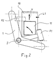
- 1 and 2 is a first embodiment with a swivel axis for displayed the scanner.
- a conveyor belt 10 is shown schematically.
- a piece of luggage is designated 11.
- On the endless conveyor belt are a corresponding number of pieces of luggage moved into the device.
- An angled frame structure 1 forms the storage for the scanner and ensures the necessary stability.
- the scanner consists of an X-ray unit 4 and a detector unit 5.
- the one above the conveyor belt and the luggage 11 arranged x-ray unit 4 consists of an x-ray tube 6 and a primary collimator 7.
- Below the conveyor belt 10 is the secondary collimator 8 and the detector 9.
- the one by the X-ray unit 4 and the detector unit 5 scanner formed is about the central axis 3 of the Frame construction 1 swiveling.
- the central axis 3 runs perpendicular to the plane of the conveyor belt 10.
- the scanner is located when the baggage is being fed in a starting position, which is designated by P1 in FIG. 2.
- the piece of luggage 11 to be checked is then fed in as long as until the advance V by a signal from a light barrier L1 is stopped.
- the scanning movement i.e. the Swivel movement in the manner of a wiper over the luggage, started.
- the scanner is moved from position 1 in brought the position 2. During this process, a 5 cm wide strip scanned.
- the pivot axis 3 is shown vertically, i.e. it is perpendicular to the level of the conveyor belt 10.
- the swivel axis 3 to the transport level of the conveyor belt 10 is inclined, then such thin or flat objects in the luggage 11 detected be perpendicular or horizontal to the transport level run.
- a frame is used through which the conveyor belt 10 is moved through.
- the swivel axis is included this modified embodiment approximately in the middle the transport level, i.e. the wave that carries the scanner is interrupted so that the conveyor belt moves through here can be.
- the scanner performs a symmetrical, circular arc-shaped movement in relation to the transport level, i.e. the The center of the swivel movement is on the central axis of the conveyor belt. As said, this embodiment is not shown.
- the plane of the frame 13, in which the carriage 14 is movable i.e. the plane of movement of the carriage perpendicular to the transport plane of the conveyor belt 10, is inclined.
- a corresponding inclination in the other plane according to FIG. 4 is also recognizable. Due to this inclination of the fluoroscopic axis 12, that goes through the x-ray unit and the detector unit, it is ensured that even thin objects in the luggage 11 are detected, the vertical or horizontal are arranged to the transport level.
- the drive motor for the carriage 14 is designated 15.
- the device according to FIGS. 3 to 5 works in this way as above in connection with the embodiment of 1 and 2 described.
- the scanner moves About the then stationary piece of luggage 11 is a Stripes captured.
- the baggage is moved on accordingly.
- the individual strips created in this way then become put together an overall picture of the contents of the luggage.
Landscapes
- Physics & Mathematics (AREA)
- High Energy & Nuclear Physics (AREA)
- Life Sciences & Earth Sciences (AREA)
- General Life Sciences & Earth Sciences (AREA)
- General Physics & Mathematics (AREA)
- Geophysics (AREA)
- Analysing Materials By The Use Of Radiation (AREA)
Abstract
Description
- Fig. 1
- eine schematische, perspektivische Ansicht der wesentlichen Teile einer Vorrichtung einer ersten Ausführungsform zur Durchführung des erfindungsgemäßen Verfahrens;
- Fig. 2
- eine schematische Draufsicht auf die Darstellung der Fig. 1;
- Fig. 3
- eine perspektivische Ansicht auf eine Vorrichtung einer zweiten Ausführungsform nach der Erfindung;
- Fig. 4
- einen Querschnitt durch die Darstellung der Fig. 3; und
- Fig. 5
- einen Längsschnitt durch die Darstellung der Fig. 3.
Claims (10)
- Verfahren zum Prüfen von Reisegepäck durch Röntgendurchleuchtung, bei dem das zu prüfende Gepäckstück auf einem Transportband in einen die Röntgenkomponenten (Röntgeneinheit und Detektoreinheit) enthaltenden Scanner bewegt wird, dadurch gekennzeichnet, daß der Scanner bei stillstehendem Gepäckstück zur Durchführung eines Scannvorganges im wesentlichen senkrecht zur Transportrichtung des Gepäckstückes über dieses bewegt wird, und daß dieser Vorgang nach getaktetem Vorrücken des Gepäckstückes in Abhängigkeit von der Größe (Länge) des Gepäckstückes wiederholt wird.
- Verfahren zum Prüfen von Reisegepäck durch Röntgendurchleuchtung, bei dem das zu prüfende Gepäckstück auf einem Transportband in einen die Röntgenkomponenten (Röntgeneinheit und Detektoreinheit) enthaltenden Scanner bewegt wird, dadurch gekennzeichnet, daß der Scanner bei stillstehendem Gepäckstück zur Durchführung eines Scannvorganges nach Art eines Scheibenwischers kreisbogenförmig über das Gepäckstück geschwenkt wird, und daß dieser Vorgang nach getaktetem Vorrücken des Gepäckstückes in Abhängigkeit von der Größe (Länge) des Gepäckstückes wiederholt wird.
- Verfahren nach Anspruch 1 oder 2, dadurch gekennzeichnet, daß sowohl bei der Hinbewegung des Scanners aus der Ausgangsstellung als auch bei seiner Rückbewegung, ein Scannvorgang durchgeführt wird, wobei das Gepäckstück zwischen beiden Scannvorgängen entsprechend vorgerückt wird.
- Vorrichtung zum Prüfen von Reisegepäck durch Röntgendurchleuchtung mit einem das zu prüfende Gepäckstück (11) in einen die Röntgenkomponenten (Röntgeneinheit und Detektoreinheit) (6 bis 9) enthaltenden Scanner bewegende Transportband (10), dadurch gekennzeichnet, daß der Scanner an einem Schlitten (14) im wesentlichen senkrecht zur Transportrichtung des Gepäckstückes über dieses bewegbar ist, und daß eine Einrichtung vorgesehen ist, die die Bewegung des Transportbandes (10) mit dem Gepäckstück beim Start des Scannvorganges unterbricht, und entsprechende Wiederholungen des Scannvorganges in Abhängigkeit von der Größe (Länge) des Gepäckstückes taktet.
- Vorrichtung zum Prüfen von Reisegepäck durch Röntgendurchleuchtung mit einem das zu prüfende Gepäckstück (11) in einen die Röntgenkomponenten (Röntgeneinheit und Detektoreinheit) (6 bis 9) enthaltenden Scanner bewegende Transportband (10), dadurch gekennzeichnet, daß der Scanner um eine zur Transportebene senkrechte Achse (3) derart schwenkbar ist, daß er zur Durchführung eines Scannvorganges eine kreisförmige Schwenkbewegung nach Art eines Scheibenwischers über das Gepäckstück (11) ausführt, und daß eine Einrichtung vorgesehen ist, die die Bewegung des Transportbandes (10) mit dem Gepäckstück (11) beim Start des Scannvorganges unterbricht, und entsprechende Wiederholungen des Scannvorganges in Abhängigkeit von der Größe (Länge) des Gepäckstückes taktet.
- Vorrichtung nach Anspruch 4 oder 5, dadurch gekennzeichnet, daß die Durchleuchtungsachse des Scanners zwischen Röntgeneinheit (4,6,7) und Detektoreinheit (5,8,9) zur Senkrechten geneigt ist.
- Vorrichtung nach Anspruch 5 oder 6, dadurch gekennzeichnet, daß die Schwenkachse (3) des durch die Röntgeneinheit (4) und Detektoreinheit (5) gebildeten Scanners zur Senkrechten geneigt ist.
- Vorrichtung nach Anspruch 4 oder 6, dadurch gekennzeichnet, daß die Röntgeneinheit (6,7) und die Detektoreinheit (8,9) derart an dem Schlitten befestigt sind, daß die Durchleuchtungsachse des Scanners zur Ebene des Transportbandes (10) geneigt ist.
- Vorrichtung nach Anspruch 5, 6 oder 7, dadurch gekennzeichnet, daß der Scanner an einer abgewinkelten Rahmenkonstruktion (1) gelagert ist, wobei die Schwenkachse (3) die Mittelachse der Rahmenkonstruktion bildet.
- Vorrichtung nach Anspruch 9, dadurch gekennzeichnet, daß die Schwenkachse (3) ungefähr durch die Mitte des Transportbandes (10) verläuft.
Priority Applications (2)
| Application Number | Priority Date | Filing Date | Title |
|---|---|---|---|
| EP99113102A EP0984302B1 (de) | 1998-09-04 | 1999-07-07 | Verfahren und Vorrichtung zur Prüfung von Reisegepäck durch Röngtendurchleuchtung |
| US09/388,711 US6301327B1 (en) | 1998-09-04 | 1999-09-02 | Method and apparatus for examining luggage by x-ray scanning |
Applications Claiming Priority (3)
| Application Number | Priority Date | Filing Date | Title |
|---|---|---|---|
| EP98116760A EP0984301A1 (de) | 1998-09-04 | 1998-09-04 | Verfahren und Vorrichtung zur Prüfung von Reisegepäck durch Röntgendurchleuchtung |
| EP98116760 | 1998-09-04 | ||
| EP99113102A EP0984302B1 (de) | 1998-09-04 | 1999-07-07 | Verfahren und Vorrichtung zur Prüfung von Reisegepäck durch Röngtendurchleuchtung |
Publications (2)
| Publication Number | Publication Date |
|---|---|
| EP0984302A1 true EP0984302A1 (de) | 2000-03-08 |
| EP0984302B1 EP0984302B1 (de) | 2003-08-20 |
Family
ID=26149608
Family Applications (1)
| Application Number | Title | Priority Date | Filing Date |
|---|---|---|---|
| EP99113102A Expired - Lifetime EP0984302B1 (de) | 1998-09-04 | 1999-07-07 | Verfahren und Vorrichtung zur Prüfung von Reisegepäck durch Röngtendurchleuchtung |
Country Status (2)
| Country | Link |
|---|---|
| US (1) | US6301327B1 (de) |
| EP (1) | EP0984302B1 (de) |
Cited By (3)
| Publication number | Priority date | Publication date | Assignee | Title |
|---|---|---|---|---|
| US6580778B2 (en) | 2001-05-23 | 2003-06-17 | Heimann Systems Gmbh | Inspection device |
| US7463721B2 (en) | 2004-03-24 | 2008-12-09 | Ge Homeland Protection Inc. | Secondary collimator for an X-ray scattering device and X-ray scattering device |
| US10506993B2 (en) | 2015-08-26 | 2019-12-17 | Koninklijke Philips N.V. | Dual energy differential phase contrast imaging |
Families Citing this family (45)
| Publication number | Priority date | Publication date | Assignee | Title |
|---|---|---|---|---|
| US6485176B1 (en) * | 2000-10-12 | 2002-11-26 | Photon Dynamics, Inc. | Inspection system with rho-theta x-ray source transport system |
| DE60215932T2 (de) * | 2001-04-03 | 2007-09-13 | L-3 Communications Security & Detection Systems, Woburn | Röntgenuntersuchungssystem |
| US7505557B2 (en) * | 2006-01-30 | 2009-03-17 | Rapiscan Security Products, Inc. | Method and system for certifying operators of x-ray inspection systems |
| US20030023592A1 (en) * | 2001-07-27 | 2003-01-30 | Rapiscan Security Products (Usa), Inc. | Method and system for certifying operators of x-ray inspection systems |
| US8275091B2 (en) | 2002-07-23 | 2012-09-25 | Rapiscan Systems, Inc. | Compact mobile cargo scanning system |
| US7963695B2 (en) | 2002-07-23 | 2011-06-21 | Rapiscan Systems, Inc. | Rotatable boom cargo scanning system |
| WO2004043705A1 (en) | 2002-11-11 | 2004-05-27 | Kittrich Corporation | Elastomeric book cover |
| US7062011B1 (en) | 2002-12-10 | 2006-06-13 | Analogic Corporation | Cargo container tomography scanning system |
| US6928141B2 (en) | 2003-06-20 | 2005-08-09 | Rapiscan, Inc. | Relocatable X-ray imaging system and method for inspecting commercial vehicles and cargo containers |
| GB2423687B (en) | 2005-02-25 | 2010-04-28 | Rapiscan Security Products Ltd | X-ray security inspection machine |
| US7471764B2 (en) | 2005-04-15 | 2008-12-30 | Rapiscan Security Products, Inc. | X-ray imaging system having improved weather resistance |
| US8213570B2 (en) | 2006-02-27 | 2012-07-03 | Rapiscan Systems, Inc. | X-ray security inspection machine |
| US20080080670A1 (en) * | 2006-09-29 | 2008-04-03 | Ge Security, Inc. | Systems and methods for classifying a substance |
| US8576982B2 (en) | 2008-02-01 | 2013-11-05 | Rapiscan Systems, Inc. | Personnel screening system |
| US8638904B2 (en) | 2010-03-14 | 2014-01-28 | Rapiscan Systems, Inc. | Personnel screening system |
| US7796733B2 (en) * | 2007-02-01 | 2010-09-14 | Rapiscan Systems, Inc. | Personnel security screening system with enhanced privacy |
| US8995619B2 (en) | 2010-03-14 | 2015-03-31 | Rapiscan Systems, Inc. | Personnel screening system |
| US7926705B2 (en) * | 2007-04-20 | 2011-04-19 | Morpho Detection, Inc. | Method and system for using a recording device in an inspection system |
| CN103064125B (zh) | 2007-06-21 | 2016-01-20 | 瑞皮斯坎系统股份有限公司 | 用于提高受指引的人员筛查的系统和方法 |
| US8003949B2 (en) | 2007-11-01 | 2011-08-23 | Rapiscan Systems, Inc. | Multiple screen detection systems |
| CA2710655C (en) | 2007-12-25 | 2018-06-12 | Rapiscan Systems, Inc. | Improved security system for screening people |
| GB0803641D0 (en) | 2008-02-28 | 2008-04-02 | Rapiscan Security Products Inc | Scanning systems |
| GB0803644D0 (en) | 2008-02-28 | 2008-04-02 | Rapiscan Security Products Inc | Scanning systems |
| GB0809110D0 (en) | 2008-05-20 | 2008-06-25 | Rapiscan Security Products Inc | Gantry scanner systems |
| WO2011063059A1 (en) | 2009-11-18 | 2011-05-26 | Rapiscan Systems, Inc. | X-ray based system and methods for inspecting a person's shoes for aviation security threats |
| GB2494963B (en) | 2010-03-14 | 2017-02-22 | Rapiscan Systems Inc | Multiple screen detection systems |
| US9218933B2 (en) | 2011-06-09 | 2015-12-22 | Rapidscan Systems, Inc. | Low-dose radiographic imaging system |
| US9111331B2 (en) | 2011-09-07 | 2015-08-18 | Rapiscan Systems, Inc. | X-ray inspection system that integrates manifest data with imaging/detection processing |
| KR102167245B1 (ko) | 2013-01-31 | 2020-10-19 | 라피스캔 시스템스, 인코포레이티드 | 이동식 보안검사시스템 |
| GB2532902B (en) | 2013-07-23 | 2020-06-03 | Rapiscan Systems Inc | Methods for improving processing speed for object inspection |
| US11280898B2 (en) | 2014-03-07 | 2022-03-22 | Rapiscan Systems, Inc. | Radar-based baggage and parcel inspection systems |
| KR20160130482A (ko) | 2014-03-07 | 2016-11-11 | 라피스캔 시스템스, 인코포레이티드 | 초광대역 검출기 |
| US10228487B2 (en) | 2014-06-30 | 2019-03-12 | American Science And Engineering, Inc. | Rapidly relocatable modular cargo container scanner |
| AU2015353439A1 (en) | 2014-11-25 | 2017-06-29 | Rapiscan Systems, Inc. | Intelligent security management system |
| US10345479B2 (en) | 2015-09-16 | 2019-07-09 | Rapiscan Systems, Inc. | Portable X-ray scanner |
| PL3764281T3 (pl) | 2016-02-22 | 2025-02-10 | Rapiscan Systems, Inc. | Sposoby identyfikacji broni palnej na obrazach radiograficznych |
| EP3520120A4 (de) | 2016-09-30 | 2020-07-08 | American Science & Engineering, Inc. | Röntgenstrahlenquelle zur zweidimensionalen abtaststrahlbildgebung |
| WO2018144630A1 (en) | 2017-01-31 | 2018-08-09 | Rapiscan Systems, Inc. | High-power x-ray sources and methods of operation |
| US11212902B2 (en) | 2020-02-25 | 2021-12-28 | Rapiscan Systems, Inc. | Multiplexed drive systems and methods for a multi-emitter X-ray source |
| US11193898B1 (en) | 2020-06-01 | 2021-12-07 | American Science And Engineering, Inc. | Systems and methods for controlling image contrast in an X-ray system |
| MX2023009276A (es) | 2021-02-23 | 2023-10-10 | Rapiscan Systems Inc | Sistemas y metodos para eliminar señales de diafonía en uno o más sistemas de escaneo que tienen múltiples fuentes de rayos x. |
| EP4371038A4 (de) | 2021-07-13 | 2025-05-28 | Rapiscan Systems, Inc. | Bildinspektionssysteme und verfahren zur integration künstlicher intelligenzplattformen dritter |
| CN118785948A (zh) | 2022-02-03 | 2024-10-15 | 拉皮斯坎控股公司 | 用于x射线线性加速器的实时能量和剂量监测的系统和方法 |
| US12474282B2 (en) | 2022-05-20 | 2025-11-18 | Rapiscan Holdings, Inc. | Systems and a method of improved material classification using energy-integrated backscatter detectors |
| EP4680116A1 (de) | 2023-03-17 | 2026-01-21 | Rapiscan Holdings, Inc. | Systeme und verfahren zur überwachung der ausgangsenergie einer hochenergetischen röntgenquelle |
Citations (8)
| Publication number | Priority date | Publication date | Assignee | Title |
|---|---|---|---|---|
| US3790799A (en) * | 1972-06-21 | 1974-02-05 | American Science & Eng Inc | Radiant energy imaging with rocking scanning |
| DE3406717A1 (de) | 1984-02-24 | 1985-08-29 | Philips Patentverwaltung Gmbh, 2000 Hamburg | Roentgenschichtaufnahmegeraet |
| DE3413348A1 (de) | 1984-04-09 | 1985-10-17 | Siemens AG, 1000 Berlin und 8000 München | Roentgenuntersuchungsgeraet |
| US4618772A (en) * | 1982-05-24 | 1986-10-21 | Siemens Gammasonics, Inc. | Nuclear imaging apparatus |
| DE3542333A1 (de) | 1985-11-29 | 1987-06-04 | Siemens Ag | Roentgenuntersuchungsgeraet |
| EP0311177A2 (de) * | 1987-10-05 | 1989-04-12 | Philips Patentverwaltung GmbH | Anordnung zur Untersuchung eines Körpers mit einer Strahlenquelle |
| WO1997012229A1 (en) | 1995-09-26 | 1997-04-03 | Vivid Technologies, Inc. | Detecting contraband by employing interactive multiprobe tomography |
| EP0825457A2 (de) | 1996-08-19 | 1998-02-25 | Analogic Corporation | Nachweisverfahren und -system für die Tomografie unter einer Mehrzahl von Winkeln |
-
1999
- 1999-07-07 EP EP99113102A patent/EP0984302B1/de not_active Expired - Lifetime
- 1999-09-02 US US09/388,711 patent/US6301327B1/en not_active Expired - Fee Related
Patent Citations (8)
| Publication number | Priority date | Publication date | Assignee | Title |
|---|---|---|---|---|
| US3790799A (en) * | 1972-06-21 | 1974-02-05 | American Science & Eng Inc | Radiant energy imaging with rocking scanning |
| US4618772A (en) * | 1982-05-24 | 1986-10-21 | Siemens Gammasonics, Inc. | Nuclear imaging apparatus |
| DE3406717A1 (de) | 1984-02-24 | 1985-08-29 | Philips Patentverwaltung Gmbh, 2000 Hamburg | Roentgenschichtaufnahmegeraet |
| DE3413348A1 (de) | 1984-04-09 | 1985-10-17 | Siemens AG, 1000 Berlin und 8000 München | Roentgenuntersuchungsgeraet |
| DE3542333A1 (de) | 1985-11-29 | 1987-06-04 | Siemens Ag | Roentgenuntersuchungsgeraet |
| EP0311177A2 (de) * | 1987-10-05 | 1989-04-12 | Philips Patentverwaltung GmbH | Anordnung zur Untersuchung eines Körpers mit einer Strahlenquelle |
| WO1997012229A1 (en) | 1995-09-26 | 1997-04-03 | Vivid Technologies, Inc. | Detecting contraband by employing interactive multiprobe tomography |
| EP0825457A2 (de) | 1996-08-19 | 1998-02-25 | Analogic Corporation | Nachweisverfahren und -system für die Tomografie unter einer Mehrzahl von Winkeln |
Cited By (3)
| Publication number | Priority date | Publication date | Assignee | Title |
|---|---|---|---|---|
| US6580778B2 (en) | 2001-05-23 | 2003-06-17 | Heimann Systems Gmbh | Inspection device |
| US7463721B2 (en) | 2004-03-24 | 2008-12-09 | Ge Homeland Protection Inc. | Secondary collimator for an X-ray scattering device and X-ray scattering device |
| US10506993B2 (en) | 2015-08-26 | 2019-12-17 | Koninklijke Philips N.V. | Dual energy differential phase contrast imaging |
Also Published As
| Publication number | Publication date |
|---|---|
| EP0984302B1 (de) | 2003-08-20 |
| US6301327B1 (en) | 2001-10-09 |
Similar Documents
| Publication | Publication Date | Title |
|---|---|---|
| EP0984302B1 (de) | Verfahren und Vorrichtung zur Prüfung von Reisegepäck durch Röngtendurchleuchtung | |
| EP2711147B1 (de) | Lebensmittelverarbeitungsvorrichtung und Verfahren zum sequentiellen Scannen von Lebensmittelprodukten | |
| EP1553405B1 (de) | Inspektionsmaschine | |
| DE3587784T2 (de) | Prüfstreifenablesevorrichtung. | |
| EP3578917B1 (de) | Vorrichtung und verfahren zum scannen von lebensmittelriegeln mit verfahrbarer scaneinheit | |
| DE3878213T2 (de) | Verfahren und vorrichtung zum pruefen eines transparenten behaelters. | |
| DE102008046416A1 (de) | Vorrichtung zur Inspektion auf Schmuggelware in Luftfrachtgutbehältern | |
| DE102008046417A1 (de) | Vorrichtung und Verfahren zur Inspektion auf Schmuggelware in Luftfrachtgutbehältern | |
| DE112007001159T5 (de) | Verfahren zur Frachtsicherheitskontrolle mit mehreren Betrachtungswinkeln | |
| EP3465173B1 (de) | Vorrichtung und verfahren zur inspektion von behältnissen | |
| DE102012008110B4 (de) | Verfahren und Vorrichtung zur Gestaltvermessung von Hohlglasartikeln | |
| DE69408023T2 (de) | Verfahren und Anordnung zum Eichen der Dickenmessanordnung des Querprofils eines flächigen Gutes | |
| DE2821319A1 (de) | Vorrichtung zur fuehrung von transportkabeln | |
| DE2626275A1 (de) | Geraet zum automatischen pruefen von achssymmetrischen werkstueckprofilen | |
| DE69013409T2 (de) | Vorrichtung zur Dimensionsmessung. | |
| DE2159430C3 (de) | Vorrichtung für chemische Analysen | |
| DE68903320T2 (de) | Vorrichtung zur kontrolle der exzentrizitaet und des diameters der isolation eines kabels. | |
| DE19738977A1 (de) | Meßgerät zum Scannen von Maßen, insbesondere Durchmessern | |
| EP2711701B1 (de) | Verfahren zum Durchleuchten von Produkten | |
| DE69104136T2 (de) | Verfahren und Gerät zum Messen des Durchmessers von Brennstofftabletten mit Laserabtastung. | |
| DE2730731A1 (de) | Vorrichtung zur bestimmung der teilchengroessenverteilung eines koernigen gutes | |
| DE69110564T2 (de) | Vorrichtung zur Bewegung eines Küvettenträgers in einem Analysator. | |
| DE2200651A1 (de) | Durchstrahlungs-Dickenmessanlage | |
| DE3314686C2 (de) | Einrichtung zum Messen des Flächeninhaltes der Projektion eines Prüfkörpers auf eine Ebene | |
| EP0984301A1 (de) | Verfahren und Vorrichtung zur Prüfung von Reisegepäck durch Röntgendurchleuchtung |
Legal Events
| Date | Code | Title | Description |
|---|---|---|---|
| PUAI | Public reference made under article 153(3) epc to a published international application that has entered the european phase |
Free format text: ORIGINAL CODE: 0009012 |
|
| AK | Designated contracting states |
Kind code of ref document: A1 Designated state(s): AT BE CH CY DE DK ES FI FR GB GR IE IT LI LU MC NL PT SE |
|
| AX | Request for extension of the european patent |
Free format text: AL;LT;LV;MK;RO;SI |
|
| 17P | Request for examination filed |
Effective date: 20000613 |
|
| AKX | Designation fees paid |
Free format text: AT BE CH CY DE DK ES FI FR GB GR IE IT LI LU MC NL PT SE |
|
| TPAD | Observations filed by third parties |
Free format text: ORIGINAL CODE: EPIDOS TIPA |
|
| 17Q | First examination report despatched |
Effective date: 20020813 |
|
| GRAH | Despatch of communication of intention to grant a patent |
Free format text: ORIGINAL CODE: EPIDOS IGRA |
|
| GRAH | Despatch of communication of intention to grant a patent |
Free format text: ORIGINAL CODE: EPIDOS IGRA |
|
| GRAA | (expected) grant |
Free format text: ORIGINAL CODE: 0009210 |
|
| AK | Designated contracting states |
Designated state(s): AT BE CH CY DE DK ES FI FR GB GR IE IT LI LU MC NL PT SE |
|
| PG25 | Lapsed in a contracting state [announced via postgrant information from national office to epo] |
Ref country code: NL Free format text: LAPSE BECAUSE OF FAILURE TO SUBMIT A TRANSLATION OF THE DESCRIPTION OR TO PAY THE FEE WITHIN THE PRESCRIBED TIME-LIMIT Effective date: 20030820 Ref country code: IT Free format text: LAPSE BECAUSE OF FAILURE TO SUBMIT A TRANSLATION OF THE DESCRIPTION OR TO PAY THE FEE WITHIN THE PRE;WARNING: LAPSES OF ITALIAN PATENTS WITH EFFECTIVE DATE BEFORE 2007 MAY HAVE OCCURRED AT ANY TIME BEFORE 2007. THE CORRECT EFFECTIVE DATE MAY BE DIFFERENT FROM THE ONE RECORDED.SCRIBED TIME-LIMIT Effective date: 20030820 Ref country code: IE Free format text: LAPSE BECAUSE OF FAILURE TO SUBMIT A TRANSLATION OF THE DESCRIPTION OR TO PAY THE FEE WITHIN THE PRESCRIBED TIME-LIMIT Effective date: 20030820 Ref country code: FI Free format text: LAPSE BECAUSE OF FAILURE TO SUBMIT A TRANSLATION OF THE DESCRIPTION OR TO PAY THE FEE WITHIN THE PRESCRIBED TIME-LIMIT Effective date: 20030820 Ref country code: CY Free format text: LAPSE BECAUSE OF FAILURE TO SUBMIT A TRANSLATION OF THE DESCRIPTION OR TO PAY THE FEE WITHIN THE PRESCRIBED TIME-LIMIT Effective date: 20030820 |
|
| REG | Reference to a national code |
Ref country code: GB Ref legal event code: FG4D Free format text: NOT ENGLISH |
|
| REG | Reference to a national code |
Ref country code: CH Ref legal event code: EP |
|
| GBT | Gb: translation of ep patent filed (gb section 77(6)(a)/1977) | ||
| REG | Reference to a national code |
Ref country code: IE Ref legal event code: FG4D Free format text: GERMAN |
|
| REF | Corresponds to: |
Ref document number: 59906652 Country of ref document: DE Date of ref document: 20030925 Kind code of ref document: P |
|
| PG25 | Lapsed in a contracting state [announced via postgrant information from national office to epo] |
Ref country code: SE Free format text: LAPSE BECAUSE OF FAILURE TO SUBMIT A TRANSLATION OF THE DESCRIPTION OR TO PAY THE FEE WITHIN THE PRESCRIBED TIME-LIMIT Effective date: 20031120 Ref country code: GR Free format text: LAPSE BECAUSE OF FAILURE TO SUBMIT A TRANSLATION OF THE DESCRIPTION OR TO PAY THE FEE WITHIN THE PRESCRIBED TIME-LIMIT Effective date: 20031120 Ref country code: DK Free format text: LAPSE BECAUSE OF FAILURE TO SUBMIT A TRANSLATION OF THE DESCRIPTION OR TO PAY THE FEE WITHIN THE PRESCRIBED TIME-LIMIT Effective date: 20031120 |
|
| PG25 | Lapsed in a contracting state [announced via postgrant information from national office to epo] |
Ref country code: PT Free format text: LAPSE BECAUSE OF FAILURE TO SUBMIT A TRANSLATION OF THE DESCRIPTION OR TO PAY THE FEE WITHIN THE PRESCRIBED TIME-LIMIT Effective date: 20040120 |
|
| REG | Reference to a national code |
Ref country code: GB Ref legal event code: 732E |
|
| NLV1 | Nl: lapsed or annulled due to failure to fulfill the requirements of art. 29p and 29m of the patents act | ||
| ET | Fr: translation filed | ||
| RAP2 | Party data changed (patent owner data changed or rights of a patent transferred) |
Owner name: YXLON INTERNATIONAL SECURITY GMBH |
|
| REG | Reference to a national code |
Ref country code: IE Ref legal event code: FD4D |
|
| REG | Reference to a national code |
Ref country code: ES Ref legal event code: FG2A Ref document number: 2205651 Country of ref document: ES Kind code of ref document: T3 |
|
| PLBI | Opposition filed |
Free format text: ORIGINAL CODE: 0009260 |
|
| PLBQ | Unpublished change to opponent data |
Free format text: ORIGINAL CODE: EPIDOS OPPO |
|
| PLAB | Opposition data, opponent's data or that of the opponent's representative modified |
Free format text: ORIGINAL CODE: 0009299OPPO |
|
| PLAX | Notice of opposition and request to file observation + time limit sent |
Free format text: ORIGINAL CODE: EPIDOSNOBS2 |
|
| PG25 | Lapsed in a contracting state [announced via postgrant information from national office to epo] |
Ref country code: LU Free format text: LAPSE BECAUSE OF NON-PAYMENT OF DUE FEES Effective date: 20040707 |
|
| 26 | Opposition filed |
Opponent name: SMITHS HELMANN GMBH Effective date: 20040519 |
|
| PGFP | Annual fee paid to national office [announced via postgrant information from national office to epo] |
Ref country code: AT Payment date: 20040722 Year of fee payment: 6 |
|
| R26 | Opposition filed (corrected) |
Opponent name: SMITHS HEIMANN GMBH Effective date: 20040519 |
|
| PG25 | Lapsed in a contracting state [announced via postgrant information from national office to epo] |
Ref country code: MC Free format text: LAPSE BECAUSE OF NON-PAYMENT OF DUE FEES Effective date: 20040731 Ref country code: LI Free format text: LAPSE BECAUSE OF NON-PAYMENT OF DUE FEES Effective date: 20040731 Ref country code: CH Free format text: LAPSE BECAUSE OF NON-PAYMENT OF DUE FEES Effective date: 20040731 Ref country code: BE Free format text: LAPSE BECAUSE OF NON-PAYMENT OF DUE FEES Effective date: 20040731 |
|
| REG | Reference to a national code |
Ref country code: FR Ref legal event code: TP |
|
| PLBB | Reply of patent proprietor to notice(s) of opposition received |
Free format text: ORIGINAL CODE: EPIDOSNOBS3 |
|
| BERE | Be: lapsed |
Owner name: *YXLON INTERNATIONAL X-RAY G.M.B.H. Effective date: 20040731 |
|
| REG | Reference to a national code |
Ref country code: CH Ref legal event code: PL |
|
| PG25 | Lapsed in a contracting state [announced via postgrant information from national office to epo] |
Ref country code: AT Free format text: LAPSE BECAUSE OF NON-PAYMENT OF DUE FEES Effective date: 20050707 |
|
| APBP | Date of receipt of notice of appeal recorded |
Free format text: ORIGINAL CODE: EPIDOSNNOA2O |
|
| APAH | Appeal reference modified |
Free format text: ORIGINAL CODE: EPIDOSCREFNO |
|
| APBQ | Date of receipt of statement of grounds of appeal recorded |
Free format text: ORIGINAL CODE: EPIDOSNNOA3O |
|
| RAP2 | Party data changed (patent owner data changed or rights of a patent transferred) |
Owner name: GE HOMELAND PROTECTION, INC. |
|
| RAP2 | Party data changed (patent owner data changed or rights of a patent transferred) |
Owner name: GE HOMELAND PROTECTION, INC. |
|
| REG | Reference to a national code |
Ref country code: GB Ref legal event code: 732E |
|
| REG | Reference to a national code |
Ref country code: GB Ref legal event code: 732E |
|
| BERE | Be: lapsed |
Owner name: *YXLON INTERNATIONAL X-RAY G.M.B.H. Effective date: 20040731 |
|
| REG | Reference to a national code |
Ref country code: FR Ref legal event code: TP Ref country code: FR Ref legal event code: CD Ref country code: FR Ref legal event code: CA |
|
| PLAB | Opposition data, opponent's data or that of the opponent's representative modified |
Free format text: ORIGINAL CODE: 0009299OPPO |
|
| APBU | Appeal procedure closed |
Free format text: ORIGINAL CODE: EPIDOSNNOA9O |
|
| PLCK | Communication despatched that opposition was rejected |
Free format text: ORIGINAL CODE: EPIDOSNREJ1 |
|
| PLBN | Opposition rejected |
Free format text: ORIGINAL CODE: 0009273 |
|
| STAA | Information on the status of an ep patent application or granted ep patent |
Free format text: STATUS: OPPOSITION REJECTED |
|
| 27O | Opposition rejected |
Effective date: 20081016 |
|
| PGFP | Annual fee paid to national office [announced via postgrant information from national office to epo] |
Ref country code: FR Payment date: 20090717 Year of fee payment: 11 Ref country code: ES Payment date: 20090727 Year of fee payment: 11 |
|
| PGFP | Annual fee paid to national office [announced via postgrant information from national office to epo] |
Ref country code: GB Payment date: 20090727 Year of fee payment: 11 Ref country code: DE Payment date: 20090729 Year of fee payment: 11 |
|
| GBPC | Gb: european patent ceased through non-payment of renewal fee |
Effective date: 20100707 |
|
| REG | Reference to a national code |
Ref country code: FR Ref legal event code: ST Effective date: 20110331 |
|
| PG25 | Lapsed in a contracting state [announced via postgrant information from national office to epo] |
Ref country code: DE Free format text: LAPSE BECAUSE OF NON-PAYMENT OF DUE FEES Effective date: 20110201 |
|
| REG | Reference to a national code |
Ref country code: DE Ref legal event code: R119 Ref document number: 59906652 Country of ref document: DE Effective date: 20110201 |
|
| PG25 | Lapsed in a contracting state [announced via postgrant information from national office to epo] |
Ref country code: FR Free format text: LAPSE BECAUSE OF NON-PAYMENT OF DUE FEES Effective date: 20100802 |
|
| PG25 | Lapsed in a contracting state [announced via postgrant information from national office to epo] |
Ref country code: GB Free format text: LAPSE BECAUSE OF NON-PAYMENT OF DUE FEES Effective date: 20100707 |
|
| REG | Reference to a national code |
Ref country code: ES Ref legal event code: FD2A Effective date: 20110818 |
|
| PG25 | Lapsed in a contracting state [announced via postgrant information from national office to epo] |
Ref country code: ES Free format text: LAPSE BECAUSE OF NON-PAYMENT OF DUE FEES Effective date: 20100708 |