EP0984342A1 - Elektronisches Uhrwerk mit einer dezimalsystembasierten Zeitanzeige - Google Patents
Elektronisches Uhrwerk mit einer dezimalsystembasierten Zeitanzeige Download PDFInfo
- Publication number
- EP0984342A1 EP0984342A1 EP98116441A EP98116441A EP0984342A1 EP 0984342 A1 EP0984342 A1 EP 0984342A1 EP 98116441 A EP98116441 A EP 98116441A EP 98116441 A EP98116441 A EP 98116441A EP 0984342 A1 EP0984342 A1 EP 0984342A1
- Authority
- EP
- European Patent Office
- Prior art keywords
- control pulses
- auxiliary control
- frequency
- electronic timepiece
- pulses
- Prior art date
- Legal status (The legal status is an assumption and is not a legal conclusion. Google has not performed a legal analysis and makes no representation as to the accuracy of the status listed.)
- Withdrawn
Links
- 238000001514 detection method Methods 0.000 claims description 9
- 230000005764 inhibitory process Effects 0.000 claims description 8
- 238000011144 upstream manufacturing Methods 0.000 claims description 8
- 230000000295 complement effect Effects 0.000 claims description 3
- 230000000903 blocking effect Effects 0.000 claims description 2
- 101000771022 Trichoderma longibrachiatum Chlorophenol O-methyltransferase Proteins 0.000 description 10
- 238000012360 testing method Methods 0.000 description 10
- 238000010586 diagram Methods 0.000 description 5
- 238000012549 training Methods 0.000 description 4
- 230000008901 benefit Effects 0.000 description 3
- 238000012937 correction Methods 0.000 description 3
- 239000010453 quartz Substances 0.000 description 3
- VYPSYNLAJGMNEJ-UHFFFAOYSA-N silicon dioxide Inorganic materials O=[Si]=O VYPSYNLAJGMNEJ-UHFFFAOYSA-N 0.000 description 3
- 238000006243 chemical reaction Methods 0.000 description 2
- 238000004519 manufacturing process Methods 0.000 description 2
- 238000000034 method Methods 0.000 description 2
- 230000008569 process Effects 0.000 description 2
- 230000015572 biosynthetic process Effects 0.000 description 1
- 238000005265 energy consumption Methods 0.000 description 1
- 238000012986 modification Methods 0.000 description 1
- 230000004048 modification Effects 0.000 description 1
Images


Classifications
-
- G—PHYSICS
- G04—HOROLOGY
- G04G—ELECTRONIC TIME-PIECES
- G04G3/00—Producing timing pulses
-
- G—PHYSICS
- G04—HOROLOGY
- G04G—ELECTRONIC TIME-PIECES
- G04G3/00—Producing timing pulses
- G04G3/02—Circuits for deriving low frequency timing pulses from pulses of higher frequency
Definitions
- the present invention relates to an electronic timepiece allowing the display of several time indications. More particularly, the present invention relates to a timepiece allowing the display of at least a first time indication conventionally based on the H eure- M inute- S econde system (HMS) and a second time indication based on a decimal system.
- HMS H eure- M inute- S econde system
- Such timepieces commonly include a time base, typically a quartz oscillator delivering pulses at a relatively high frequency, for example 32,768 Hz.
- a frequency divider circuit composed of a succession of N division stages binary (flip-flops) connected in cascade, is coupled to the time base so as to deliver control pulses whose frequency is reduced by a factor of 2 N.
- the division of time is conventionally based on the H-M-S system, i.e. a system where the day is divided into 24 hours, 1 hour being divided into 60 minutes, and 1 minute in 60 seconds.
- a division of time based on the decimal system consists in return to divide the day, no longer according to the conventional scheme above, but successively, in tenths of a day (equivalent to 2.4 hours or 144 minutes), themselves divided into hundredths of a day (equivalent to 14.4 minutes or 864 seconds), then in thousandths of a day (equivalent to 86.4 seconds), etc.
- the decimal system is an alternative interesting to the H-M-S system currently in force. This system allows in particular to get rid of inherent conversion issues in H-M-S format. This alternative is more logical and understandable for the already customary user of the decimal system.
- the display of a time indication based on the decimal system because of its particular format, thus stands out more easily from a conventional time indication based on the H-M-S system. This is particularly advantageous in the case of a timepiece allowing the display of several separate time indications, because the risk of confusion when reading these are thus greatly reduced.
- a first solution consists in providing a base of additional time to deliver pulses at a frequency corresponding to a multiple of the desired frequency, for example 10'000 Hz.
- One circuit frequency divider having for example a ratio of division equivalent to 86,400 would thus generate control pulses at a frequency of 1 / 8.64 Hz.
- This first trivial solution thus implies the use of two division chains (time base + frequency divider circuit) separate. We will look however, limit the number of components required to produce the display control pulses.
- a second solution is to generate control pulses at the frequency adequate, for example 1 / 86.4 or 1 / 8.64 Hz, in with 864 pulses delivered at 10 or 100 Hz respectively.
- These frequencies are indeed typically available for timing functions when these are planned. It is however hardly conceivable in practical, mainly for consumption reasons in energy, to operate continuously, a counter by 864 controlled by pulses at 10 or 100 Hz.
- the object of the present invention is therefore to propose an electronic timepiece in which control pulses enabling training and display of a system-based time indication decimal are generated from command pulses a time indication based on the H-M-S system conventionally used.
- Another object of the present invention is to provide an electronic timepiece allowing the generation of control pulses for a display of a time indication based on the decimal system of simple manufacturing and having an energy consumption scaled down.
- the present invention relates to an electronic timepiece permitting the display of at least a first time indication based on the H eure- M inute- S econde system, this timepiece comprising a base of time delivering pulses to a frequency divider circuit comprising N binary division stages and making it possible to deliver first control pulses to first means for displaying said first time indication, this timepiece being characterized in that it also allows the display of at least a second time indication based on a decimal system, this timepiece further comprising generation means making it possible to deliver, from auxiliary control pulses originating from said time base , second control pulses to second means for displaying said second time indication.
- An advantage of the present invention lies in the makes it possible to adapt the electronics of a conventional timepiece so that it allows the display of a time indication based on the decimal system, and this at a lower cost.
- Another advantage of the present invention lies in the fact that the means used to generate the second pulses of time indication commands based on the decimal system are inexpensive and simple Manufacturing.
- FIG. 1 there is shown in Figure 1, in the form of a simplified block diagram, a timepiece constituting a first embodiment of the present invention.
- This timepiece includes in series a time base 2, typically formed of a quartz oscillator, a frequency divider circuit 4 comprising N binary division stages 4.1 to 4.N and delivering first control pulses I 1 , and first display means 6 controlled by the first control pulses I 1 .
- the above-mentioned numerical values will be used as a non-limiting example.
- the first display means 6 are controlled by the first control pulses I 1 and are arranged in a conventional manner so that they allow the formation and display of a first time indication H 1 based on the HMS system.
- the timepiece according to the present invention further comprises generation means 14 delivering second control pulses I 2 whose frequency is determined by the decimal division adopted, that is to say 1 / 86.4 Hz in the case where a division into thousandths of a day is adopted.
- These generation means 14 are controlled by auxiliary control pulses I L from the time base 2 and delivered, in this embodiment, at the output of one of the binary division stages 4.1 to 4.N of the circuit frequency divider 4, this stage being indicated by the reference 4.L and being able to be chosen from the set of binary division stages 4.1 to 4.N.
- the frequency of the auxiliary control pulses I L is equivalent to the frequency of the pulses delivered by the time base 2 reduced by a factor 2 L.
- second display means 16 are connected. These second display means 16 are controlled by the second control pulses I 2 and are arranged so that they allow training and display of a second time indication H 2 based on the decimal system.
- FIG. 2 there is shown in Figure 2, in the form of a simplified block diagram, a timepiece constituting a second embodiment of the present invention.
- This timepiece comprises in series, the time base 2, the frequency divider circuit 4, the first and second display means 6 and 16, as well as the means 14 for generating second control pulses I 2 .
- This timepiece further comprises N * additional binary division stages 4.N + 1 to 4.N + N * connected following the frequency divider circuit 4.
- the generation means 14 are controlled by auxiliary pulses of command I L also originating from time base 2 and delivered, in this embodiment, at the output of the additional binary division stages 4.N + 1 to 4.N + N *.
- the frequency of the auxiliary control pulses I L is equivalent, in this case, to the frequency of the pulses delivered by the time base 2 reduced by a factor 2 N + N * .
- FIGS. 1 and 2 thus allow the display of a first time indication H 1 based on the HMS system, and of a second time indication H 2 based on the decimal system.
- the second control pulses I 2 are thus generated from auxiliary control pulses I L originating from the time base 2.
- timepiece according to this invention further comprises correction means allowing the adjustment of different indications hours.
- correction means allowing the adjustment of different indications hours. These means of correction have not been described here and are not shown in Figures 1 and 2. A person skilled in the art will nevertheless be able to realize these means of correction so that they allow to adjust so adequate each time indication.
- additional display means may in addition be planned so as to allow training and the display of additional time indications based on the H-M-S system or the decimal system.
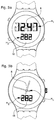
- FIGS. 3a and 3b show plan views of timepieces according to the present invention illustrating different possibilities for displaying the time indications H 1 and H 2 .
- the first display means 6 of the first time indication H 1 can be produced in the form of a digital display allowing, for example, the display of the time indication H 1 according to a conventional "HH: MM" format.
- these first display means can for example comprise, as shown in FIG. 3b, first and second hands driven by electromechanical means (not shown) and allowing the display of the hours and the minutes respectively.
- the second display means 16 of the second time indication H 2 are advantageously formed, as illustrated in FIGS. 3a and 3b, of a digital display comprising, in this example, 3 digits so as to allow the display of the second time indication H 2 in thousandths of a day.
- These second display means 16 can however also be produced in the form of an analog display with needles driven by electromechanical means in a similar manner to the first display means 6 illustrated in FIG. 3b.
- the second control pulses I 2 must be delivered at a frequency of 1 /86.4 Hz or 1 / 8.64 Hz respectively.
- the auxiliary control pulses IL are used, according to the present invention, to generate the second control pulses I 2 .
- the frequency of the auxiliary control pulses I L is determined by the binary division stage at the output of which these are delivered. According to the first embodiment described in FIG. 1, this frequency thus equals the frequency of the pulses delivered by the time base 2 reduced by a factor 2 L. According to the second embodiment described in FIG. 2, this frequency is equivalent to the frequency of the pulses delivered by the time base 2 reduced by a factor 2 N + N * .
- the division ratio of the frequency of the auxiliary control pulses I L by the frequency of the second control pulses I 2 defines a numerical value corresponding to the average number of auxiliary control pulses I L to be counted to generate a control pulse I 2 . Since the frequency of the pulses delivered by the time base 2 is typically equivalent to a binary power, the division ratio defines a non-integer numerical value due to the decimal division of the day.
- integers n and n + 1 are respectively defined directly below and above the aforementioned division ratio. These integers n and n + 1 thus correspond respectively to the integers directly lower and greater than the average number of auxiliary control pulses I L to be counted to generate a control pulse I 2 .
- the second control pulses I 2 are generated at an average frequency corresponding to the desired frequency, for example 1 / 86.4 Hz or 1 / 8.64 HZ, n and n + 1 auxiliary control pulses I L are thus successively counted according to a determined counting sequence.
- This counting sequence is formed by a succession of counting operations of n and n + 1 auxiliary control pulses I L.
- the division ratio defined above determines the period as well as the number of counting operations at the end of which the second control pulses I 2 are generated at the desired average frequency.
- This counting sequence is further preferably formed so that the deviations generated at during the counting sequence are reduced to minimum.
- the frequency division ratio is equivalent to 86.4.
- the division ratio further defines that 5 control pulses I 2 must be generated during a period of 432 seconds.
- the counting sequence repeated 200 times over a period of 24 hours, is thus formed of a succession of 5 counting operations.
- the maximum deviation generated during the counting sequence is thus limited to +/- 0.4 seconds, ie of the order of 0.5% of the period of the second control pulses I 2 .
- the frequency division ratio is equivalent to 10.8.
- the division ratio further defines that 5 control pulses I 2 must be generated during a period of 432 seconds.
- the counting sequence repeated 200 times over a period of 24 hours, is thus formed of a succession of 5 counting operations.
- the maximum deviation generated during the counting sequence is thus limited to +/- 3.2 seconds, ie of the order of 4% of the period of the second control pulses I 2 .
- the frequency division ratio is equivalent to 8.64.
- the division report further defines that 25 I 2 command pulses are to be generated over a period of 216 seconds.
- the counting sequence repeated 400 times over a period of 24 hours, is thus formed of a succession of 25 counting operations.
- the maximum deviation generated during the counting sequence is thus limited to +/- 0.48 seconds, or about 5.5% of the period of the second control pulses I 2 .
- auxiliary control pulses I L determines on the one hand the precision with which the second control pulses I 2 are generated, and on the other hand the size of the registers / counters necessary for counting of auxiliary control pulses I L.
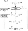
- FIG. 4 presents a flowchart of setting work of the generation means 14 constituting a first alternative embodiment according to the present invention.
- these means of generation 14 can be made advantageously under the form of an integrated circuit comprising a programmed microprocessor.
- Those skilled in the art will know from the indications provided here, carry out the programming the microprocessor, so as to make it perform the functions described.
- the counting sequence begins at the block indicated by the reference 400.
- a counter register COMPT is incremented at each auxiliary control pulse I L.
- This counter register COMPT comprises a number of bits sufficient to allow the counting of at least n + 1 auxiliary control pulses I L.
- this counter register COMPT comprises at least 7 bits.
- a first test is performed at block 404 so as to check whether the value of the counter register COMPT has reached the value n.
- the counter register COMPT is incremented in block 402 at each auxiliary control pulse I L. as long as the value of the latter is less than the value n, this being indicated by the affirmative output of the test block 404.
- test block 406 leads to the third test indicated in block 408. At this stage, it is checked, according to the counting sequence, whether the counter register COMPT must be stopped at the value n. If necessary, a control pulse I 2 is generated at block 410, that is to say after the counting of n auxiliary control pulses I L. Otherwise, the counter register COMPT is incremented in block 402 and, following the affirmative result of the test executed in block 406, the control pulse I 2 is then generated in block 410, ie after the counting of n + 1 pulses control auxiliaries I L.
- the counter register COMPT is initialized at block 412 and the process begins again at block 400.
- this table includes binary values representative of the counting operation to be performed, either for example the binary value "0" if it is necessary to count n auxiliary control pulses I L or the binary value "1" whether to count n + 1 auxiliary control pulses I L.
- a binary word comprising as many bits as counting operations easily makes it possible to produce the table representative of the counting sequence.
- the register containing the value of the second hourly indication H 2 being displayed makes it possible to define an indexing value of the various entries of the table by a simple calculation of the modulo.
- Modulo obviously means the arithmetic operation giving the remainder of a division by a determined number.
- test which is performed in block 408 is thus performed in looking for the corresponding value in the table.
- a register containing the value of the second hourly indication H 2 being displayed, or at least the value (0 to 9) of the thousandths of days displayed, will be used.
- a modulo-5 operation on the value of this register thus makes it possible to obtain an indexing value (0 to 4) of the table.
- an alternative to using a table consists in directly using the result of the modulo-5 operation on the register containing the value of the thousandths of days displayed.
- a register containing the value of thousandths of a day displayed in order to obtain by a modulo-5 operation a indexing value (0 to 4) of the table.
- test which is performed in block 408 is thus performed in looking for the corresponding value in this table.
- a modulo-25 operation on the value of this register thus makes it possible to obtain an indexing value (0 to 24) from the table.
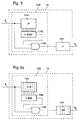
- FIG. 5 illustrates a second alternative embodiment of the generation means 14 making it possible to deliver the second control pulses I 2 .
- these generation means 14 comprise a primary counter 141 arranged to count n auxiliary control pulses I L , and inhibition means 142 of the primary counter 141.
- the inhibition means 142 are controlled by the auxiliary control pulses I L and are located upstream of the primary counter 141 so as to periodically inhibit a determined number of auxiliary control pulses I L at the input of the latter.
- the second control pulses I 2 are delivered to the output of the primary counter 141.
- the inhibition means 142 preferably comprise a secondary counter 144 arranged to count m auxiliary control pulses I L , a detection logic circuit 146 coupled to the different stages of the secondary counter 144 so as to detect k intermediate states of the latter (chosen from states 0 to m-1) during which the auxiliary control pulses I L are inhibited, as well as an AND logic gate, indicated by the reference 148, comprising 2 inputs, one being inverted and connected to the output of the detection logic 146 and the other receiving the auxiliary control pulses I L.
- the inhibition means 142 thus make it possible to periodically inhibit, that is to say during a period when m pulses I L are delivered, k auxiliary control pulses I L upstream of the primary counter 141.
- the logic detection circuit 146 When one of the k intermediate states is detected by the logic detection circuit 146, the latter thus sends back an inhibition signal blocking the output of the logic gate AND for the duration of an auxiliary control pulse I L so that the primary counter 141 does not "see” this pulse and does not count it.
- FIG. 5a a first example of the second alternative embodiment presented in FIG. 5 has been illustrated, applied in the case where the second control pulses I 2 are generated at an average frequency of 1 / 86.4 Hz from d auxiliary control pulses I L having a frequency of 1 Hz, ie in the case where the generation means 14 are connected to the output of the last binary division stage 4.N of the frequency divider circuit 4 (in accordance with the first mode of realization presented in figure 1).
- control pulses I 2 are thus delivered to the output of the primary counter 141 during a period of 432 seconds, that is to say at the average frequency of 1 / 86.4 Hz.
- the counter by 86 can easily be produced at by means of a 7-bit binary counter arranged so as to be initialized after 86 pulses.
- the counter par 216 requires an 8-bit counter arranged to be initialized after 216 pulses.
- control pulses I 2 are thus delivered to the output of the primary counter 141 during a period of 432 seconds, that is to say at the average frequency of 1 / 86.4 Hz.
- the counters by 10 and by 27 thus require 4 and 5 bit counters respectively.
- FIG. 5c a third example of the second variant presented in FIG. 5 has been illustrated, applied in the case where the second control pulses I 2 are generated at an average frequency of 1 / 8.64 Hz, ie 25 pulses during a period of 216 seconds, from auxiliary control pulses I L having a frequency of 1 Hz, that is to say in the case where the generation means 14 are connected to the output of the last stage of binary division 4 .N of the frequency divider circuit 4 (in accordance with the first embodiment presented in FIG. 1).
- control pulses I 2 are thus delivered to the output of the primary counter 141 during a period of 216 seconds, that is to say at the average frequency of 1 / 8.64 Hz.
- the counters by 8 and by 27 thus require 3 and 5 bit counters respectively.
- the frequency of the auxiliary control pulses I L defines the precision at which the second control pulses I 2 are delivered.
- the higher the frequency of the auxiliary control pulses I L the greater the precision at which the second control pulses I 2 are delivered.
- this in return involves the use of counters comprising a large number of stages.
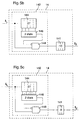
- FIG. 6 illustrates a third alternative embodiment of the generation means 14 making it possible to deliver the second control pulses I 2 .
- these generation means 14 comprise a primary counter 241 arranged to count n + 1 auxiliary control pulses I L , and initialization means 242 coupled to the primary counter 241.
- the second control pulses I 2 are delivered to the output of the primary counter 241 and are used to control the initialization means 242 so as to periodically initialize the primary counter 241 with a value k corresponding to a complementary number of auxiliary control pulses I L.
- the initialization means 242 preferably comprise a secondary counter 244 arranged to count m second control pulses I 2 and an initialization circuit 246 coupled to the different stages of the primary counter 241 so as to periodically initialize the latter, that is to say say after m pulses I 2 have been delivered, with a value k corresponding to the additional number of auxiliary control pulses I L necessary for the primary counter 241 to deliver the second control pulses I 2 at the appropriate average frequency.
- the primary counter 241 is initialized with a value k so as to compensate for the missing auxiliary control pulses I L.
- FIG. 6a an example of the third variant presented in FIG. 6 has been illustrated, applied in the case where the second control pulses I 2 are generated at an average frequency of 1 / 86.4 Hz from auxiliary control pulses I L having a frequency of 1 Hz, ie in the case where the generation means 14 are connected to the output of the last binary division stage 4.N (4.15) of the frequency divider circuit 4 (in accordance with the first embodiment shown in Figure 1).
- control pulses I 2 are thus delivered to the output of the primary counter 241 during a period of 432 seconds, that is to say at the average frequency of 1 / 86.4 Hz.
- the counters by 87 and by 5 require 7 and 3 bit counters respectively.
Landscapes
- Physics & Mathematics (AREA)
- General Physics & Mathematics (AREA)
- Electric Clocks (AREA)
Priority Applications (1)
| Application Number | Priority Date | Filing Date | Title |
|---|---|---|---|
| EP98116441A EP0984342A1 (de) | 1998-08-31 | 1998-08-31 | Elektronisches Uhrwerk mit einer dezimalsystembasierten Zeitanzeige |
Applications Claiming Priority (1)
| Application Number | Priority Date | Filing Date | Title |
|---|---|---|---|
| EP98116441A EP0984342A1 (de) | 1998-08-31 | 1998-08-31 | Elektronisches Uhrwerk mit einer dezimalsystembasierten Zeitanzeige |
Publications (1)
| Publication Number | Publication Date |
|---|---|
| EP0984342A1 true EP0984342A1 (de) | 2000-03-08 |
Family
ID=8232554
Family Applications (1)
| Application Number | Title | Priority Date | Filing Date |
|---|---|---|---|
| EP98116441A Withdrawn EP0984342A1 (de) | 1998-08-31 | 1998-08-31 | Elektronisches Uhrwerk mit einer dezimalsystembasierten Zeitanzeige |
Country Status (1)
| Country | Link |
|---|---|
| EP (1) | EP0984342A1 (de) |
Cited By (1)
| Publication number | Priority date | Publication date | Assignee | Title |
|---|---|---|---|---|
| US7035169B2 (en) | 2002-07-25 | 2006-04-25 | Eta Sa Manufacture Horlogère Suisse | Event planner timepiece |
Citations (10)
| Publication number | Priority date | Publication date | Assignee | Title |
|---|---|---|---|---|
| US3284715A (en) * | 1963-12-23 | 1966-11-08 | Rca Corp | Electronic clock |
| US3945194A (en) * | 1973-12-15 | 1976-03-23 | Itt Industries, Inc. | Electronic quartz clock with integrated circuits |
| FR2391508A1 (fr) * | 1977-05-18 | 1978-12-15 | Verger Maurice | Compteur de temps calculatrice electronique |
| US4175378A (en) * | 1974-02-19 | 1979-11-27 | Shelton Vernon E | Decimal timekeeping instrument |
| US4185452A (en) * | 1976-07-08 | 1980-01-29 | Arihiko Ikeda | Digital time display system |
| US4408897A (en) * | 1982-09-22 | 1983-10-11 | Ebauches Electroniques S.A. | Electronic timepiece having a digital frequency correction circuit |
| US4413350A (en) * | 1981-01-12 | 1983-11-01 | General Datacomm Industries, Inc. | Programmable clock rate generator |
| US4926400A (en) * | 1989-11-30 | 1990-05-15 | Morton Rachofsky | Combined twenty-four (24)/twenty-five (25) hour clock |
| EP0566398A2 (de) * | 1992-04-17 | 1993-10-20 | Seiko Epson Corporation | Digitale Trimmschaltung |
| US5444674A (en) * | 1994-06-08 | 1995-08-22 | Sellie; Clifford N. | Hand held decimal timer with improved frequency division |
-
1998
- 1998-08-31 EP EP98116441A patent/EP0984342A1/de not_active Withdrawn
Patent Citations (10)
| Publication number | Priority date | Publication date | Assignee | Title |
|---|---|---|---|---|
| US3284715A (en) * | 1963-12-23 | 1966-11-08 | Rca Corp | Electronic clock |
| US3945194A (en) * | 1973-12-15 | 1976-03-23 | Itt Industries, Inc. | Electronic quartz clock with integrated circuits |
| US4175378A (en) * | 1974-02-19 | 1979-11-27 | Shelton Vernon E | Decimal timekeeping instrument |
| US4185452A (en) * | 1976-07-08 | 1980-01-29 | Arihiko Ikeda | Digital time display system |
| FR2391508A1 (fr) * | 1977-05-18 | 1978-12-15 | Verger Maurice | Compteur de temps calculatrice electronique |
| US4413350A (en) * | 1981-01-12 | 1983-11-01 | General Datacomm Industries, Inc. | Programmable clock rate generator |
| US4408897A (en) * | 1982-09-22 | 1983-10-11 | Ebauches Electroniques S.A. | Electronic timepiece having a digital frequency correction circuit |
| US4926400A (en) * | 1989-11-30 | 1990-05-15 | Morton Rachofsky | Combined twenty-four (24)/twenty-five (25) hour clock |
| EP0566398A2 (de) * | 1992-04-17 | 1993-10-20 | Seiko Epson Corporation | Digitale Trimmschaltung |
| US5444674A (en) * | 1994-06-08 | 1995-08-22 | Sellie; Clifford N. | Hand held decimal timer with improved frequency division |
Cited By (1)
| Publication number | Priority date | Publication date | Assignee | Title |
|---|---|---|---|---|
| US7035169B2 (en) | 2002-07-25 | 2006-04-25 | Eta Sa Manufacture Horlogère Suisse | Event planner timepiece |
Similar Documents
| Publication | Publication Date | Title |
|---|---|---|
| WO2000013067A1 (fr) | Piece d'horlogerie electronique comportant une indication horaire fondee sur un system decimal | |
| EP0589465B1 (de) | Analoguhr mit Warnungsmitteln für eine Betriebsartänderung | |
| EP0143279A1 (de) | Uhr mit analogischer und numerischer Anzeige | |
| EP0142440A2 (de) | Vorrichtung zum Erzeugen einer, bezüglich einer Referenzfrequenz gebrochenen Frequenz | |
| CH690526A5 (fr) | Procédé pour maintenir et ajuster la précision de pièces d'horlogerie électroniques et pièces d'horlogerie utilisant un tel procédé. | |
| EP0071506B1 (de) | Digitales Verfahren und digitale Einrichtung zur Berichtigung von Phasenfehlern eines abgetasteten Signals und seine Anwendung zur Berichtigung von Fernsehsignalen | |
| EP0049652B1 (de) | Einrichtung zur zeitlichen Kompression und Einrichtung zur zeitlichen Dekompression von Daten | |
| FR2666707A1 (fr) | Dispositif de division de frequence programmable. | |
| EP0683441B1 (de) | Elektronische Uhr mit Minutenwiederholungsfunktion | |
| EP0475862B1 (de) | Schneller Zähler/Teiler und dessen Verwendung in einem Zähler mit Impulsunterdrückung | |
| EP0984342A1 (de) | Elektronisches Uhrwerk mit einer dezimalsystembasierten Zeitanzeige | |
| FR2485221A1 (fr) | Dispositif electronique de mise a l'heure avec decalage d'une heure pour dispositif d'horlogerie electronique | |
| EP1807738B1 (de) | Elektronische uhr mit multifunktion und navigationshilfe, die speziell für weltraummissionen geeignet ist | |
| WO2006018157A1 (fr) | Montre affichant la date et une indication astronomique | |
| EP0027250A1 (de) | Uhrwerk mit Sekundenanzeige auf Wunsch | |
| EP0217164B1 (de) | Elektronisches Uhrwerk mit analoger Anzeige, die ein Sekunden anzeigendes Organ enthält | |
| EP3018827A1 (de) | Gray-code-zähler und analog-digitalwandler, der einen solchen zähler verwendet | |
| EP3748438B1 (de) | Messung der präzision einer uhr, die einen kontinuierlich drehenden elektromechanischen transducer in ihrer analogen uhrzeitanzeigevorrichtung umfasst | |
| EP0092522B1 (de) | Umkehrbarer Schrittmotor und Verfahren zur Steuerung des Motors | |
| EP0105837B1 (de) | Nichtlineare Zählschaltung | |
| FR2695273A1 (fr) | Ligne à retard programmable, circuit à retard programmable et oscillateur programmable. | |
| EP3779611B1 (de) | Elektromechanische armbanduhr | |
| CH618577B5 (de) | ||
| EP0202495B1 (de) | Zeitgeber | |
| FR3025901A1 (fr) | Dispositif de generation d'un signal d'horloge par multiplication de frequence |
Legal Events
| Date | Code | Title | Description |
|---|---|---|---|
| PUAI | Public reference made under article 153(3) epc to a published international application that has entered the european phase |
Free format text: ORIGINAL CODE: 0009012 |
|
| AK | Designated contracting states |
Kind code of ref document: A1 Designated state(s): AT BE CH CY DE DK ES FI FR GB GR IE IT LI LU MC NL PT SE |
|
| AX | Request for extension of the european patent |
Free format text: AL;LT;LV;MK;RO;SI |
|
| AKX | Designation fees paid | ||
| STAA | Information on the status of an ep patent application or granted ep patent |
Free format text: STATUS: THE APPLICATION IS DEEMED TO BE WITHDRAWN |
|
| 18D | Application deemed to be withdrawn |
Effective date: 20000911 |
|
| REG | Reference to a national code |
Ref country code: DE Ref legal event code: 8566 |