EP0984343B1 - Procédé pour meuler des pièces composites - Google Patents
Procédé pour meuler des pièces composites Download PDFInfo
- Publication number
- EP0984343B1 EP0984343B1 EP99123806A EP99123806A EP0984343B1 EP 0984343 B1 EP0984343 B1 EP 0984343B1 EP 99123806 A EP99123806 A EP 99123806A EP 99123806 A EP99123806 A EP 99123806A EP 0984343 B1 EP0984343 B1 EP 0984343B1
- Authority
- EP
- European Patent Office
- Prior art keywords
- workpiece
- grinding
- eccentricity
- region
- concentric
- Prior art date
- Legal status (The legal status is an assumption and is not a legal conclusion. Google has not performed a legal analysis and makes no representation as to the accuracy of the status listed.)
- Expired - Lifetime
Links
Images


Classifications
-
- B—PERFORMING OPERATIONS; TRANSPORTING
- B24—GRINDING; POLISHING
- B24B—MACHINES, DEVICES, OR PROCESSES FOR GRINDING OR POLISHING; DRESSING OR CONDITIONING OF ABRADING SURFACES; FEEDING OF GRINDING, POLISHING, OR LAPPING AGENTS
- B24B51/00—Arrangements for automatic control of a series of individual steps in grinding a workpiece
-
- B—PERFORMING OPERATIONS; TRANSPORTING
- B24—GRINDING; POLISHING
- B24B—MACHINES, DEVICES, OR PROCESSES FOR GRINDING OR POLISHING; DRESSING OR CONDITIONING OF ABRADING SURFACES; FEEDING OF GRINDING, POLISHING, OR LAPPING AGENTS
- B24B19/00—Single-purpose machines or devices for particular grinding operations not covered by any other main group
- B24B19/08—Single-purpose machines or devices for particular grinding operations not covered by any other main group for grinding non-circular cross-sections, e.g. shafts of elliptical or polygonal cross-section
- B24B19/12—Single-purpose machines or devices for particular grinding operations not covered by any other main group for grinding non-circular cross-sections, e.g. shafts of elliptical or polygonal cross-section for grinding cams or camshafts
- B24B19/125—Single-purpose machines or devices for particular grinding operations not covered by any other main group for grinding non-circular cross-sections, e.g. shafts of elliptical or polygonal cross-section for grinding cams or camshafts electrically controlled, e.g. numerically controlled
-
- B—PERFORMING OPERATIONS; TRANSPORTING
- B24—GRINDING; POLISHING
- B24B—MACHINES, DEVICES, OR PROCESSES FOR GRINDING OR POLISHING; DRESSING OR CONDITIONING OF ABRADING SURFACES; FEEDING OF GRINDING, POLISHING, OR LAPPING AGENTS
- B24B49/00—Measuring or gauging equipment for controlling the feed movement of the grinding tool or work; Arrangements of indicating or measuring equipment, e.g. for indicating the start of the grinding operation
- B24B49/02—Measuring or gauging equipment for controlling the feed movement of the grinding tool or work; Arrangements of indicating or measuring equipment, e.g. for indicating the start of the grinding operation according to the instantaneous size and required size of the workpiece acted upon, the measuring or gauging being continuous or intermittent
- B24B49/04—Measuring or gauging equipment for controlling the feed movement of the grinding tool or work; Arrangements of indicating or measuring equipment, e.g. for indicating the start of the grinding operation according to the instantaneous size and required size of the workpiece acted upon, the measuring or gauging being continuous or intermittent involving measurement of the workpiece at the place of grinding during grinding operation
- B24B49/045—Specially adapted gauging instruments
-
- B—PERFORMING OPERATIONS; TRANSPORTING
- B24—GRINDING; POLISHING
- B24B—MACHINES, DEVICES, OR PROCESSES FOR GRINDING OR POLISHING; DRESSING OR CONDITIONING OF ABRADING SURFACES; FEEDING OF GRINDING, POLISHING, OR LAPPING AGENTS
- B24B5/00—Machines or devices designed for grinding surfaces of revolution on work, including those which also grind adjacent plane surfaces; Accessories therefor
- B24B5/36—Single-purpose machines or devices
- B24B5/42—Single-purpose machines or devices for grinding crankshafts or crankpins
-
- G—PHYSICS
- G05—CONTROLLING; REGULATING
- G05B—CONTROL OR REGULATING SYSTEMS IN GENERAL; FUNCTIONAL ELEMENTS OF SUCH SYSTEMS; MONITORING OR TESTING ARRANGEMENTS FOR SUCH SYSTEMS OR ELEMENTS
- G05B19/00—Program-control systems
- G05B19/02—Program-control systems electric
- G05B19/18—Numerical control [NC], i.e. automatically operating machines, in particular machine tools, e.g. in a manufacturing environment, so as to execute positioning, movement or co-ordinated operations by means of program data in numerical form
- G05B19/182—Numerical control [NC], i.e. automatically operating machines, in particular machine tools, e.g. in a manufacturing environment, so as to execute positioning, movement or co-ordinated operations by means of program data in numerical form characterised by the machine tool function, e.g. thread cutting, cam making, tool direction control
- G05B19/184—Generation of cam-like surfaces
-
- G—PHYSICS
- G05—CONTROLLING; REGULATING
- G05B—CONTROL OR REGULATING SYSTEMS IN GENERAL; FUNCTIONAL ELEMENTS OF SUCH SYSTEMS; MONITORING OR TESTING ARRANGEMENTS FOR SUCH SYSTEMS OR ELEMENTS
- G05B19/00—Program-control systems
- G05B19/02—Program-control systems electric
- G05B19/18—Numerical control [NC], i.e. automatically operating machines, in particular machine tools, e.g. in a manufacturing environment, so as to execute positioning, movement or co-ordinated operations by means of program data in numerical form
- G05B19/404—Numerical control [NC], i.e. automatically operating machines, in particular machine tools, e.g. in a manufacturing environment, so as to execute positioning, movement or co-ordinated operations by means of program data in numerical form characterised by control arrangements for compensation, e.g. for backlash, overshoot, tool offset, tool wear, temperature, machine construction errors, load, inertia
-
- G—PHYSICS
- G05—CONTROLLING; REGULATING
- G05B—CONTROL OR REGULATING SYSTEMS IN GENERAL; FUNCTIONAL ELEMENTS OF SUCH SYSTEMS; MONITORING OR TESTING ARRANGEMENTS FOR SUCH SYSTEMS OR ELEMENTS
- G05B19/00—Program-control systems
- G05B19/02—Program-control systems electric
- G05B19/18—Numerical control [NC], i.e. automatically operating machines, in particular machine tools, e.g. in a manufacturing environment, so as to execute positioning, movement or co-ordinated operations by means of program data in numerical form
- G05B19/416—Numerical control [NC], i.e. automatically operating machines, in particular machine tools, e.g. in a manufacturing environment, so as to execute positioning, movement or co-ordinated operations by means of program data in numerical form characterised by control of velocity, acceleration or deceleration
- G05B19/4166—Controlling feed or in-feed
-
- G—PHYSICS
- G05—CONTROLLING; REGULATING
- G05B—CONTROL OR REGULATING SYSTEMS IN GENERAL; FUNCTIONAL ELEMENTS OF SUCH SYSTEMS; MONITORING OR TESTING ARRANGEMENTS FOR SUCH SYSTEMS OR ELEMENTS
- G05B2219/00—Program-control systems
- G05B2219/30—Nc systems
- G05B2219/33—Director till display
- G05B2219/33078—Error table, interpolate between two stored values to correct error
-
- G—PHYSICS
- G05—CONTROLLING; REGULATING
- G05B—CONTROL OR REGULATING SYSTEMS IN GENERAL; FUNCTIONAL ELEMENTS OF SUCH SYSTEMS; MONITORING OR TESTING ARRANGEMENTS FOR SUCH SYSTEMS OR ELEMENTS
- G05B2219/00—Program-control systems
- G05B2219/30—Nc systems
- G05B2219/36—Nc in input of data, input key till input tape
- G05B2219/36103—Adapt, update machining parameters automatically as function of state of processing
-
- G—PHYSICS
- G05—CONTROLLING; REGULATING
- G05B—CONTROL OR REGULATING SYSTEMS IN GENERAL; FUNCTIONAL ELEMENTS OF SUCH SYSTEMS; MONITORING OR TESTING ARRANGEMENTS FOR SUCH SYSTEMS OR ELEMENTS
- G05B2219/00—Program-control systems
- G05B2219/30—Nc systems
- G05B2219/37—Measurements
- G05B2219/37308—Measure workpiece relieved from stress, redrawn, disengaged tool
-
- G—PHYSICS
- G05—CONTROLLING; REGULATING
- G05B—CONTROL OR REGULATING SYSTEMS IN GENERAL; FUNCTIONAL ELEMENTS OF SUCH SYSTEMS; MONITORING OR TESTING ARRANGEMENTS FOR SUCH SYSTEMS OR ELEMENTS
- G05B2219/00—Program-control systems
- G05B2219/30—Nc systems
- G05B2219/37—Measurements
- G05B2219/37339—Eccentricity, cylindricity, circularity
-
- G—PHYSICS
- G05—CONTROLLING; REGULATING
- G05B—CONTROL OR REGULATING SYSTEMS IN GENERAL; FUNCTIONAL ELEMENTS OF SUCH SYSTEMS; MONITORING OR TESTING ARRANGEMENTS FOR SUCH SYSTEMS OR ELEMENTS
- G05B2219/00—Program-control systems
- G05B2219/30—Nc systems
- G05B2219/37—Measurements
- G05B2219/37345—Dimension of workpiece, diameter
-
- G—PHYSICS
- G05—CONTROLLING; REGULATING
- G05B—CONTROL OR REGULATING SYSTEMS IN GENERAL; FUNCTIONAL ELEMENTS OF SUCH SYSTEMS; MONITORING OR TESTING ARRANGEMENTS FOR SUCH SYSTEMS OR ELEMENTS
- G05B2219/00—Program-control systems
- G05B2219/30—Nc systems
- G05B2219/37—Measurements
- G05B2219/37525—Mean, average values, statistical derived values
-
- G—PHYSICS
- G05—CONTROLLING; REGULATING
- G05B—CONTROL OR REGULATING SYSTEMS IN GENERAL; FUNCTIONAL ELEMENTS OF SUCH SYSTEMS; MONITORING OR TESTING ARRANGEMENTS FOR SUCH SYSTEMS OR ELEMENTS
- G05B2219/00—Program-control systems
- G05B2219/30—Nc systems
- G05B2219/37—Measurements
- G05B2219/37576—Post-process, measure worpiece after machining, use results for new or same
-
- G—PHYSICS
- G05—CONTROLLING; REGULATING
- G05B—CONTROL OR REGULATING SYSTEMS IN GENERAL; FUNCTIONAL ELEMENTS OF SUCH SYSTEMS; MONITORING OR TESTING ARRANGEMENTS FOR SUCH SYSTEMS OR ELEMENTS
- G05B2219/00—Program-control systems
- G05B2219/30—Nc systems
- G05B2219/45—Nc applications
- G05B2219/45156—Grind on lathe
-
- G—PHYSICS
- G05—CONTROLLING; REGULATING
- G05B—CONTROL OR REGULATING SYSTEMS IN GENERAL; FUNCTIONAL ELEMENTS OF SUCH SYSTEMS; MONITORING OR TESTING ARRANGEMENTS FOR SUCH SYSTEMS OR ELEMENTS
- G05B2219/00—Program-control systems
- G05B2219/30—Nc systems
- G05B2219/49—Nc machine tool, till multiple
- G05B2219/49177—Runout, eccentricity, imbalance of tool or workpiece
-
- G—PHYSICS
- G05—CONTROLLING; REGULATING
- G05B—CONTROL OR REGULATING SYSTEMS IN GENERAL; FUNCTIONAL ELEMENTS OF SUCH SYSTEMS; MONITORING OR TESTING ARRANGEMENTS FOR SUCH SYSTEMS OR ELEMENTS
- G05B2219/00—Program-control systems
- G05B2219/30—Nc systems
- G05B2219/49—Nc machine tool, till multiple
- G05B2219/49188—Proportional compensation from middle to end of elongated workpiece
-
- G—PHYSICS
- G05—CONTROLLING; REGULATING
- G05B—CONTROL OR REGULATING SYSTEMS IN GENERAL; FUNCTIONAL ELEMENTS OF SUCH SYSTEMS; MONITORING OR TESTING ARRANGEMENTS FOR SUCH SYSTEMS OR ELEMENTS
- G05B2219/00—Program-control systems
- G05B2219/30—Nc systems
- G05B2219/49—Nc machine tool, till multiple
- G05B2219/49342—Select between concentric and eccentric regions of a workpiece
-
- G—PHYSICS
- G05—CONTROLLING; REGULATING
- G05B—CONTROL OR REGULATING SYSTEMS IN GENERAL; FUNCTIONAL ELEMENTS OF SUCH SYSTEMS; MONITORING OR TESTING ARRANGEMENTS FOR SUCH SYSTEMS OR ELEMENTS
- G05B2219/00—Program-control systems
- G05B2219/30—Nc systems
- G05B2219/50—Machine tool, machine tool null till machine tool work handling
- G05B2219/50056—Profile, for operation on I-, T-profiles or other elongated profiles
-
- G—PHYSICS
- G05—CONTROLLING; REGULATING
- G05B—CONTROL OR REGULATING SYSTEMS IN GENERAL; FUNCTIONAL ELEMENTS OF SUCH SYSTEMS; MONITORING OR TESTING ARRANGEMENTS FOR SUCH SYSTEMS OR ELEMENTS
- G05B2219/00—Program-control systems
- G05B2219/30—Nc systems
- G05B2219/50—Machine tool, machine tool null till machine tool work handling
- G05B2219/50059—Record profile error, used for next machining pass
Definitions
- This invention concerns a method of grinding workpieces to form components which include both concentric and eccentric cylindrical regions.
- a component may be an internal combustion engine crankshaft, which includes both concentric journal bearing regions and eccentric crankpins.
- the invention is applicable to any such workpiece which is to be ground to size and finish, and such workpieces will be referred to herein as composite workpieces.
- the workpiece is rotated about its primary axis and each of the concentric sections are ground by moving a grinding wheel into a grinding position and removing material from the workpiece to produce a concentric cylindrical region thereon, in a conventional manner.
- the workpiece has been rotated about the axis of each eccentric region in turn, and conventional cylindrical grinding is employed to remove material so as to produce a cylindrical bearing surface at each eccentric region, just as if the element were a concentric cylindrical region of an overall workpiece.
- the workpiece has been rotated about its primary axis so that the eccentric regions precess eccentrically around the primary axis of rotation, as for example do the crankpins of a crankshaft when the latter is mounted in and is rotated in an engine.
- the grinding wheel has been aligned with an eccentric region and then been advanced and retracted under computer control in synchronism with the precession of the eccentric region so that the grinding wheel remains in contact therewith at all times.
- the region is thereby ground at all positions of its precession.
- the grinding wheel is withdrawn and the workpiece or grinding wheel is repositioned axially so that another eccentric region is aligned with the grinding wheel, ready for a similar grinding operation at the new location.
- a process requiring two grinding machines involves considerable down-time as components are moved from one machine to another.
- a computer control unit for a crankshaft milling/grinding machine in which a digital transducer coupled to the work spindle continuously transmits positional data of the crankshaft to the computer, to enable it to control the machining of the crankpins and cheeks of the crankshaft.
- EP-A-0576043 discloses an NC machine tool for grinding a non-circular workpiece.
- a work spindle and tool slide are moved in accordance with a compensated profile data stored in a computer memory, and positional data of the spindle and slide are measured at low machining load and compared with the profile data to ascertain whether the compensation is within a predetermined tolerance.
- the invention thus allows a workpiece having both concentric and eccentric cylindrical regions thereon to be ground on a single grinding machine without demounting the workpiece from the machine.
- This enables a workpiece to be left in place between centres whilst different regions therealong are ground to form cylindrical surfaces some of which are concentric with the primary axis of rotation of the workpiece, and others of which are eccentric relative thereto.
- crankshafts which have both eccentric regions and journal bearing regions which have to be ground as cylindrical surfaces concentric with the primary axis of rotation of the crankshaft.
- the measuring of the workpiece region occurs after it has been stress relieved, which may be achieved merely by disengaging the grinding wheel, but may involve removing the workpiece from the grinding machine for gauging, then the careful replacement of the workpiece back in position.
- the setting up process may be performed for a concentric cylindrical region approximately midway along the said axial length of the workpiece, and proportionately reduced corrections are applied to the wheelfeed programme instructions or control signals for similar cylindrical regions which are to be ground and which are displaced from the mid position towards the supported ends of the workpiece.
- This alternative method involves the steps of concentrically grinding all of the concentric surfaces of a workpiece without introducing any compensation for unwanted process induced eccentricity thereafter making measurements on the workpiece to determine the extent and angular position of any unwanted eccentricity for each of the ground regions, and separately adjusting the wheelfeed programme instructions or control signals used to control the wheel feed during subsequent grinding of each said region of the same of a similar workpiece, so as to compensate individually for each said region for any process-induced eccentricity.
- each stage may be preferable at each stage to grind a number of workpieces which together form a sample, and to perform eccentricity measurements on the workpieces in each sample, and thereby determine the extent of any unwanted eccentricity both in terms of angular position and radial extent for each region of each workpiece in each sample, and to determine the mean unwanted eccentricity and mean angular position of such eccentricity for each sample, for use as the basis for the correction to the wheel feed control signals for subsequent grinding.
- the process for determining what is to be the final set of control signals for the wheelfeel can be terminated either if all of the measurements of unwanted eccentricity in all of the workpieces in a sample fall within desired limits, or if the mean of all the measurements of unwanted eccentricity fall within desired limits.
- the particular criterion used may depend upon the specification for the component concerned.
- the invention may be applied to the above method in which the workpiece is a crankshaft having concentric regions and eccentric cylindrical crankpin regions, and in which a software controlled crankpin following facility is used to permit the grinding wheel to follow the relatively excessive eccentric movement of the crankpins as the crankshaft rotates during grinding comprising the steps of adapting the software to provide at a smaller scale a complementary eccentricity to the unwanted eccentricity which is introduced into the concentric cylindrical surfaces of the workpiece as a consequence of grinding process forces exerted as such surfaces are ground, and which tends to appear after the workpiece is stress relieved, so as to cancel out the process-induced eccentricity.
- crankpins and journal bearing regions on elongate crankshafts Whilst the invention is of particular application to the grinding of crankpins and journal bearing regions on elongate crankshafts, it is to be understood that it is equally applicable to the grinding of any composite workpiece so as to remove eccentricity which the grinding process can introduce into the workpiece, and which becomes evident as the latter becomes unstressed.
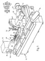
- Figure 1 shows a grinding machine 10 having a grinding wheel 12 driven by a motor 14 and mounted on a wheelhead 16 for movement towards and away from a workpiece 18 along a linear track 20 under the control of the wheelfeed drive motor 22.
- the workpiece 18 is mounted no a carriage 70 itself slidable on a slideway 72 and driven therealong to position the workpiece relative to the wheel, via a drive 74.
- the workpiece is mounted between centres in a tailstock 24 and a headstock 26 (themselves mounted on the carriage 70).
- the headstock houses a motor (not shown) for rotating the workpiece 18 via a chuck 28.
- the workpiece shown is a crankshaft of an internal combustion engine and includes offset crankpins 30 (which are eccentric to the main workshaft axis), and cylindrical bearing regions 31, which are to be ground to size, each bearing region constituting a cylindrical workpiece region for grinding which should be concentric with the workpiece axis.
- a computer 32 loaded with workpiece data and oeprating programmes controls the operation of the machine and inter alia moves the wheelhead 16 towards and away from the workpiece 18 as the workpiece rotates, so as to maintain contact between the wheel and the journal bearing region being ground.
- Some data can be entered via the keyboard 33.
- Data/results/process steps can be displayed on the screen 35.
- a gauge, generally designated 34, is carried by the wheel head assembly for gauging the diameter of the regions being ground. This can be done while the workpiece is rotated slowly, and preferably without the grinding wheel in contact, after grinding.
- the gauge is shown in its parked, non-operating position in Figure 1. During gauging it is advanced so that the fingers of the gauge (described in more detail with reference to Figure 2) are first located on the opposite side of the workpiece from the wheel 12, so that they can be lowered and moved back towards the wheel so as to be located above and below the workpiece, and then moved towards the latter until they touch it at diametrically opposite regions for gauging.
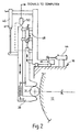
- the gauge will allow the gauging of crankpins such as 30 as they are ground, but Figure 2 shows how the fingers 36 and 38 can also engage a cylindrical bearing region 31.
- Pneumatic drives 44, 46 and 48 produce relative movement between the gauge assembly and the wheelhead 16, between the gauge assembly and the workpiece, and between the two fingers 36 and 38.
- a sensor 50 determines the spacing between the fingers 36, 38 and provides a size signal for the computer 32, from which the diameter of the workpiece region between the fingers can be computed.
- the sensor can also provide a signal indicative of the linear oscillatory movement of the gauge fingers caused by any eccentricity in the ground region, by locking the two fingers 36, 38 together but spaced so as to just lightly clamp the workplace therebetween, and rotating the latter slowly and observing any movement of 38 relative to sensor 50.
- Figure 3 shows diagrammatically the grinding wheel 12, the wheelhead 16, the slide 20, and a different type of gauge from that shown in Figures 1 and 2.
- This engages a cylindrical workpiece region 31 by means of two fixed converging fingers 52, 54, with a sensor 55 producing a signal from which the distance between the converging fingers at which the fingers make contact with the workpiece can be determined.
- the computer 32 receives the signal along line 56 and can compute therefrom the diameter of the workpiece region.
- Position and wheelhead drive signals from the computer 32 pass via line 59. Not shown are the signal paths from the computer 32 to the other drives for moving the gauge into and out of engagement and controlling the speed of rotation of the wheel and the crankshaft.
- this type of gauge can also be used to determine any eccentricity in the rotating workpiece region, by urging the gauge fingers 52, 54 into contact as shown and converting any in line movement of the gauge assembly 60, due to eccentricity, as the workpiece rotates into an appropriate electrical signal using a transducer such as 57.
- Wheel position signals from a transducer/encoder 41 are passed to the computer 32 via line 43.
- An encoder 37 or other transducer converts rotation of the workpiece 31 into angular informature. Signals along line 39 enable the phase of any eccentricity of 31 to be determined by the computer 32.
- the feed will be stopped in response to signals derived from the wheel position and/or the in-process gauge 34 in a diameter measuring mode, and sampled by the machine control computer 32.
- the instantaneous size of the region 31 being ground can be continuously sampled by the machine control computer.
- the controlling computer If one or two or more consecutive samples of region 31 size, are found to be at or below the target size, the controlling computer immediately stops the grinding feed and initiates a feed dwell.
- This dwell measured as N workpiece turns, permits the region being ground to achieve good geometric roundness and a stable size. This procedure gives an optimum response to fast grinding feeds commensurate with fast manufacturing times.
- the controlling computer stores a number of consecutive samples of size measured at different angular positions relative to the gauge fingers so that it can calculate an average value of the workpiece region diameter.
- the average diameter value may be calculated, and this value used to calculate the feed distance to achieve the desired final size of the region.
- the controlling computer then initiates an incremental feed to final size.
- the gauge having completed its work, can be retracted, with the object of minimising manufacturing time. Because the feed to final size is not being controlled by gauge, it does not have to be slow but can be optimised to eliminate the build-up of machining vibrations and/or minimise machining time.
- the grinding wheel can be retracted, initially at a slow rate so as not to leave any grinding wheel breakaway mark, and then at a faster rate to minimise manufacturing time.
- machining may be achieved without such in process gauging, simply by controlling the wheel feed and gauging components off-line, and correcting for process induced eccentricity in accordance with the present invention and for wheel wear by appropriate adjustment as the grinding of a batch of workpieces progresses.
- Figure 4 illustrates the steps of a method of grinding an elongate component having a number of different regions therealong which are to be cylindrically ground either concentrically or eccentrically to the primary axis of the component, and in which process induced eccentricity is corrected for all such regions whether ground to be concentric or eccentric to the primary axis.
Landscapes
- Engineering & Computer Science (AREA)
- Mechanical Engineering (AREA)
- Human Computer Interaction (AREA)
- Manufacturing & Machinery (AREA)
- Physics & Mathematics (AREA)
- General Physics & Mathematics (AREA)
- Automation & Control Theory (AREA)
- Constituent Portions Of Griding Lathes, Driving, Sensing And Control (AREA)
- Grinding Of Cylindrical And Plane Surfaces (AREA)
- Portable Nailing Machines And Staplers (AREA)
Claims (9)
- Une méthode d'installation d'une affûteuse (10) contrôlée par ordinateur pour affûter une longue pièce à travailler en composite (18) ayant des régions concentriques cylindriques (31), ainsi qu'une compensation pour une excentricité induite par le processus dans au moins une desdites régions concentriques, dans laquelle ladite région concentrique est cylindriquement affûtée dans sa forme finale, caractérisée par les étapes de mesure (50) de quelque excentricité non souhaitée induite par le processus d'affûtage ainsi que la ou les position(s) angulaire(s) dans ladite région concentrique, et de réglage des instructions de programme ou des signaux de contrôle du dispositif de la meule stockés dans l'ordinateur (32) contrôlant l'affûteuse, afin que durant l'affûtage ultérieur de la pièce à travailler, le dispositif de la meule soit contrôlé de façon à affûter une forme excentrique égale et opposée à celle mesurée, annulant ainsi toute excentricité induite par le processus.
- Une méthode telle qu'elle est définie dans la revendication 1, dans laquelle l'étape de mesure de toute excentricité non souhaitée s'effectue après que ladite région concentrique ait été stabilisée.
- Une méthode telle qu'elle est définie dans la revendication 1 ou la revendication 2, dans lesquelles la pluralité de régions concentriques doit être affûtée à des positions axialement espacées le long de la pièce en composite à travailler dont les extrémités sont soutenues pour l'affûtage, le processus d'installation s'accomplissant pour ladite région concentrique environ au milieu de la longueur axiale de la pièce à travailler, et dans laquelle des corrections sont proportionnellement apportées aux instructions de programme ou aux signaux de contrôle du dispositif de la meule pour des régions cylindriques similaires qui doivent être affûtées et qui sont déplacées de la position médiane vers les extrémités soutenues de la pièce à travailler.
- Une méthode telle qu'elle est définie dans la revendication 1 ou la revendication 2, dans lesquelles les régions vers le centre de la pièce à travailler ont tendance à avoir besoin d'un plus grand degré de compensation d'excentricité que les régions adjacentes auxdites extrémités, soutenues laquelle méthode implique les étapes d'affûtage cylindrique de toutes les surfaces cylindriques concentriques de la pièce à travailler sans introduction de compensation pour l'excentricité non souhaitée induite par le processus et la prise de mesures par la suite sur la pièce à travailler pour déterminer la position étendue et la position angulaire de toute excentricité non souhaitée pour chacune des régions affûtées et régler séparément les instructions de programme ou les signaux de contrôle du dispositif de la meule à utiliser pour contrôler le dispositif de la meule durant l'affûtage consécutif de chacune desdites régions des mêmes pièces à travailler ou similaires, afin de compenser individuellement chacune desdites régions pour toute excentricité induite par le processus.
- Une méthode telle qu'elle est définie dans la revendication 4, dans lesquelles la pièce à travailler d'origine est réaffûtée après le processus d'installation en utilisant les instructions de programme ou les signaux de contrôle corrigés du dispositif de la meule, et une autre étape de mesure est pratiquée sur la pièce à travailler réaffûtée et une deuxième série de corrections est apportée aux instructions de programme et aux signaux de contrôle, avant le réaffûtage de la pièce à travailler originale ou l'affûtage d'autres pièces à travailler similaires.
- Une méthode telle qu'elle est définie dans les revendications 1 à 5, dans lesquelles au lieu de produire une seule et unique pièce à travailler sur laquelle les mesures sont prises durant l'étape d'installation, à chaque étape un certain nombre de pièces à travailler sont affûtées de façon à former un échantillon, et les mesures d'excentricité sont effectuées sur les pièces à travailler de chacun des échantillons, ce qui permet ainsi de déterminer l'amplitude de toute excentricité non souhaitée tant en position angulaire qu'en position radiale pour chaque région de chaque pièce à travailler de chaque échantillon, et l'excentricité moyenne non souhaitée ainsi que la position angulaire moyenne d'une telle excentricité sont déterminées pour chaque échantillon, chacun étant utilisé comme base pour la correction des instructions de programme ou des signaux de contrôle du dispositif de la meule pour l'affûtage consécutif.
- Une méthode telle qu'elle est définie dans les revendications 1 à 5, dans lesquelles les instructions ou signaux de contrôle modifiés du programme de dispositif de la meule, dérivés de la procédure d'installation, sont utilisés pour contrôler la commande de dispositif de la meule lors de l'affûtage des surfaces cylindriques des pièces à travailler en composite identiques à ceux utilisés lors du processus d'installation.
- Une méthode telle qu'elle est définie dans les revendications 1 à 7, dans lesquelles la pièce à travailler est un vilebrequin ayant des régions concentriques et des régions de maneton excentriques et cylindriques, et dans lesquelles une fonction de maneton contrôlé par logiciel est utilisée afin que la meule à affûter puisse suivre le mouvement excentrique relativement excessif des manetons pendant que le vilebrequin tourne durant l'affûtage comprenant les étapes d'adaptation du logiciel pour fournir, à une plus petite échelle, une excentricité supplémentaire à l'excentricité non souhaitée qui est introduite dans les surfaces cylindriques concentriques de la pièce à travailler résultant des forces de processus d'affûtage exercées lorsque les surfaces sont affûtées, et qui tend à apparaítre après que la pièce à travailler ait été stabilisée afin d'annuler l'excentricité induite par le processus.
- Une méthode telle qu'elle est définie dans la revendication 8, dans laquelle le degré de ladite excentricité complémentaire fournie est tel que lorsque la pièce à travailler affûtée est stabilisée après l'affûtage, la région devient concentrique par rapport au premier axe de la pièce à travailler, et dans laquelle la même gestion par ordinateur du dispositif de la meule bien qu'à une plus petite échelle, est utilisée pour affûter le maneton en utilisant la même meule sur la même machine.
Applications Claiming Priority (3)
| Application Number | Priority Date | Filing Date | Title |
|---|---|---|---|
| GB9608351 | 1996-04-23 | ||
| GBGB9608351.4A GB9608351D0 (en) | 1996-04-23 | 1996-04-23 | Composite component grinding method and apparatus |
| EP97919518A EP0895614B1 (fr) | 1996-04-23 | 1997-04-22 | Procede et dispositif pour meuler des pieces composites |
Related Parent Applications (1)
| Application Number | Title | Priority Date | Filing Date |
|---|---|---|---|
| EP97919518A Division EP0895614B1 (fr) | 1996-04-23 | 1997-04-22 | Procede et dispositif pour meuler des pieces composites |
Publications (3)
| Publication Number | Publication Date |
|---|---|
| EP0984343A2 EP0984343A2 (fr) | 2000-03-08 |
| EP0984343A3 EP0984343A3 (fr) | 2000-03-15 |
| EP0984343B1 true EP0984343B1 (fr) | 2003-01-15 |
Family
ID=10792483
Family Applications (2)
| Application Number | Title | Priority Date | Filing Date |
|---|---|---|---|
| EP97919518A Expired - Lifetime EP0895614B1 (fr) | 1996-04-23 | 1997-04-22 | Procede et dispositif pour meuler des pieces composites |
| EP99123806A Expired - Lifetime EP0984343B1 (fr) | 1996-04-23 | 1997-04-22 | Procédé pour meuler des pièces composites |
Family Applications Before (1)
| Application Number | Title | Priority Date | Filing Date |
|---|---|---|---|
| EP97919518A Expired - Lifetime EP0895614B1 (fr) | 1996-04-23 | 1997-04-22 | Procede et dispositif pour meuler des pieces composites |
Country Status (10)
| Country | Link |
|---|---|
| US (1) | US6411861B1 (fr) |
| EP (2) | EP0895614B1 (fr) |
| AU (1) | AU2395897A (fr) |
| BR (1) | BR9706668A (fr) |
| CA (1) | CA2225962C (fr) |
| DE (2) | DE69718520T2 (fr) |
| ES (2) | ES2171258T3 (fr) |
| GB (2) | GB9608351D0 (fr) |
| MX (1) | MX9804292A (fr) |
| WO (1) | WO1997040432A1 (fr) |
Cited By (1)
| Publication number | Priority date | Publication date | Assignee | Title |
|---|---|---|---|---|
| CN101154098B (zh) * | 2006-09-28 | 2011-01-19 | 株式会社捷太格特 | 数字控制器及其程序写入方法以及由此控制的切削机 |
Families Citing this family (24)
| Publication number | Priority date | Publication date | Assignee | Title |
|---|---|---|---|---|
| US6602109B1 (en) * | 1998-12-16 | 2003-08-05 | University Of Massachusetts | Grinding wheel system |
| GB9928825D0 (en) * | 1999-12-06 | 2000-02-02 | Unova Uk Ltd | Improvements in and relating to grinding |
| JP4051872B2 (ja) * | 2000-09-29 | 2008-02-27 | 株式会社ジェイテクト | 加工部の測定方法及び加工方法 |
| KR100782393B1 (ko) * | 2000-10-26 | 2007-12-07 | 신에쓰 가가꾸 고교 가부시끼가이샤 | 광섬유모재 잉곳의 제조방법 |
| DE10104287B4 (de) * | 2001-01-30 | 2006-08-24 | Sirona Dental Systems Gmbh | Verfahren zur Bestimmung aktueller Positionsdaten eines Bearbeitungswerkzeuges und Vorrichtung hierzu |
| US7657757B2 (en) | 2003-04-30 | 2010-02-02 | Freescale Semiconductor, Inc. | Semiconductor device and method utilizing variable mode control with block ciphers |
| DE10344293A1 (de) * | 2003-09-23 | 2005-04-21 | Walter Ag | Schleifmaschine mit Rundlaufkorrektur |
| TWI388397B (zh) * | 2004-02-25 | 2013-03-11 | Studer Ag Fritz | 用於工作件加工的加工機 |
| US7226340B2 (en) * | 2004-03-05 | 2007-06-05 | Alfred H. Schutte Gmbh & Co. Kg | Grinding machine |
| JP5401757B2 (ja) * | 2006-11-30 | 2014-01-29 | 株式会社ジェイテクト | 加工装置 |
| DE102008007175B4 (de) * | 2008-02-01 | 2010-06-02 | Erwin Junker Maschinenfabrik Gmbh | Verfahren zum Schleifen der Haupt- und Hublager einer Kurbelwelle durch Außenrundschleifen und Vorrichtung zur Durchführung des Verfahrens |
| JP5228554B2 (ja) * | 2008-03-19 | 2013-07-03 | 株式会社ジェイテクト | 非真円箇所研削盤における工作物異常回転検出装置 |
| GB2475391B (en) * | 2009-07-28 | 2013-02-27 | Komatsu Ntc Ltd | Grinding machine and measurement device |
| CN102099155B (zh) * | 2009-07-28 | 2014-03-26 | 小松Ntc株式会社 | 研磨机及其测量装置 |
| JP5708324B2 (ja) * | 2011-07-11 | 2015-04-30 | 日本精工株式会社 | 研削加工盤及び研削加工方法 |
| EP2650081B1 (fr) * | 2012-04-13 | 2013-11-27 | Supfina Grieshaber GmbH & Co. KG | Procédé et dispositif de finition d'une surface de pièce usinée |
| JP6186739B2 (ja) * | 2013-02-15 | 2017-08-30 | 株式会社ジェイテクト | 研削盤および研削方法 |
| DE102013222359B4 (de) * | 2013-11-04 | 2018-05-09 | Gebr. Heller Maschinenfabrik Gmbh | Verfahren zur Feinbearbeitung von Wellen, insbesondere Kurbelwellen, sowie Feinbearbeitungsanlage dafür |
| DE102013226733B4 (de) * | 2013-12-19 | 2021-12-23 | Erwin Junker Grinding Technology A.S. | VERFAHREN UND SCHLEIFMASCHINE ZUM MESSEN UND ERZEUGEN EINER AUßENSOLLKONTUR EINES WERKSTÜCKES DURCH SCHLEIFEN |
| CN103802023B (zh) * | 2014-03-06 | 2016-04-27 | 吉林大学 | 数控磨床凸轮磨削的速度优化控制方法 |
| US10132167B2 (en) | 2014-06-16 | 2018-11-20 | United Technologies Corporation | Methods for creating a film cooled article for a gas turbine engine |
| CN104325405B (zh) * | 2014-11-19 | 2017-02-08 | 武汉大学 | 一种超细丝磨具定位系统及方法 |
| EP4048474A4 (fr) * | 2019-10-24 | 2023-11-22 | Fives Landis Corp. | Procédé de meulage et de tournage d'une pièce à travailler |
| CN114683105A (zh) * | 2020-12-29 | 2022-07-01 | 广东美芝精密制造有限公司 | 一种空调压缩机曲轴的加工方法 |
Family Cites Families (26)
| Publication number | Priority date | Publication date | Assignee | Title |
|---|---|---|---|---|
| GB674065A (en) * | 1948-06-10 | 1952-06-18 | Robert Musyl | Improvements in or relating to machines for grinding the main bearing pins and crank pins of crankshafts |
| JPS5457285A (en) * | 1977-10-14 | 1979-05-08 | Komatsu Ltd | Crankshaft mirror control device |
| DE2822346C2 (de) * | 1978-05-22 | 1985-09-05 | GFM Gesellschaft für Fertigungstechnik und Maschinenbau GmbH, Steyr | Elektrische numerische Programmsteuerung für Kurbelwellenfräsmaschinen und Kurbelwellen-Schleifmaschinen |
| AT373405B (de) * | 1978-10-04 | 1984-01-25 | Gfm Fertigungstechnik | Elektrische steuereinrichtung fuer eine spanabhebende werkzeugmaschine zum bearbeiten von kurbelwellen |
| DE2918249A1 (de) * | 1979-05-05 | 1980-11-06 | Goetze Ag | Maschine zum vorzugsweise spanenden umfangsbearbeiten von unrunden werkstuecken, insbesondere kolbenringen |
| JPS58192750A (ja) * | 1982-05-03 | 1983-11-10 | Toyoda Mach Works Ltd | 研削盤 |
| US4580224A (en) * | 1983-08-10 | 1986-04-01 | E. W. Bliss Company, Inc. | Method and system for generating an eccentricity compensation signal for gauge control of position control of a rolling mill |
| JPH0698554B2 (ja) * | 1986-09-22 | 1994-12-07 | 豊田工機株式会社 | 数値制御加工装置 |
| DE3702594C3 (de) * | 1987-01-29 | 1995-04-06 | Fortuna Werke Maschf Ag | Verfahren und Vorrichtung zum Schleifen von Nocken an Nockenwellen |
| GB2206067B (en) * | 1987-06-25 | 1991-05-15 | Litton Uk Ltd | Crankpin grinders |
| DE3828594C2 (de) * | 1987-08-24 | 2002-04-25 | Toshiba Machine Co Ltd | Numerisch gesteuerte Werkzeugmaschine und Verfahren zum Steuern des damit durchgeführten Schleifvorgangs |
| FR2623741B1 (fr) * | 1987-11-26 | 1990-04-27 | Peugeot | Ensemble de rectification des manetons de vilebrequins |
| GB2219231A (en) * | 1988-06-04 | 1989-12-06 | Ford Motor Co | Grinding workpieces |
| JP3030046B2 (ja) * | 1990-03-22 | 2000-04-10 | 豊田工機株式会社 | 非真円創成装置 |
| FR2665526A1 (fr) * | 1990-08-02 | 1992-02-07 | Meseltron Sa | Dispositif pour la mesure de diametres de pieces cylindriques en cours d'usinage. |
| US6205371B1 (en) * | 1990-08-11 | 2001-03-20 | Dieter Wolter-Doll | Method and apparatus for detecting machining flaws, especially caused by grinding machines |
| JP3021156B2 (ja) * | 1991-12-25 | 2000-03-15 | オークマ株式会社 | 非真円形状加工装置における加工誤差補正方法 |
| JP2811515B2 (ja) * | 1992-04-25 | 1998-10-15 | オークマ株式会社 | 非円形ワークの研削方法及び装置 |
| JPH068105A (ja) * | 1992-06-29 | 1994-01-18 | Komatsu Ltd | 円筒形状加工装置 |
| CA2081699C (fr) * | 1992-08-14 | 1998-06-09 | James D. Phillips | Meule de maneton |
| GB2283192B (en) * | 1993-10-20 | 1997-07-16 | Western Atlas Uk Ltd | Improvements in and relating to grinding machines |
| GB9509294D0 (en) * | 1995-05-06 | 1995-06-28 | Western Atlas Uk Ltd | Improvements relating to guaging the diameter of cylindrical workpiece sections |
| GB9514042D0 (en) * | 1995-07-10 | 1995-09-06 | Western Atlas Uk Ltd | Improvements in and relating to machine tools |
| GB9603260D0 (en) * | 1996-02-16 | 1996-04-17 | Western Atlas Uk Ltd | Grinding method and apparatus for cylindrical workpieces |
| GB9608352D0 (en) * | 1996-04-23 | 1996-06-26 | Western Atlas Uk Ltd | Workpiece grinding method and apparatus |
| US6113461A (en) * | 1996-09-30 | 2000-09-05 | Ntn Corporation | Grinding method utilizing grinding sharpness of grinding element |
-
1996
- 1996-04-23 GB GBGB9608351.4A patent/GB9608351D0/en active Pending
-
1997
- 1997-04-22 WO PCT/GB1997/001109 patent/WO1997040432A1/fr not_active Ceased
- 1997-04-22 EP EP97919518A patent/EP0895614B1/fr not_active Expired - Lifetime
- 1997-04-22 EP EP99123806A patent/EP0984343B1/fr not_active Expired - Lifetime
- 1997-04-22 ES ES97919518T patent/ES2171258T3/es not_active Expired - Lifetime
- 1997-04-22 AU AU23958/97A patent/AU2395897A/en not_active Abandoned
- 1997-04-22 GB GB9708088A patent/GB2314285B/en not_active Expired - Fee Related
- 1997-04-22 CA CA002225962A patent/CA2225962C/fr not_active Expired - Fee Related
- 1997-04-22 BR BR9706668A patent/BR9706668A/pt not_active IP Right Cessation
- 1997-04-22 DE DE69718520T patent/DE69718520T2/de not_active Expired - Fee Related
- 1997-04-22 DE DE69708858T patent/DE69708858T2/de not_active Expired - Fee Related
- 1997-04-22 US US09/011,081 patent/US6411861B1/en not_active Expired - Fee Related
- 1997-04-22 ES ES99123806T patent/ES2190171T3/es not_active Expired - Lifetime
-
1998
- 1998-05-29 MX MX9804292A patent/MX9804292A/es not_active IP Right Cessation
Cited By (1)
| Publication number | Priority date | Publication date | Assignee | Title |
|---|---|---|---|---|
| CN101154098B (zh) * | 2006-09-28 | 2011-01-19 | 株式会社捷太格特 | 数字控制器及其程序写入方法以及由此控制的切削机 |
Also Published As
| Publication number | Publication date |
|---|---|
| DE69718520D1 (de) | 2003-02-20 |
| ES2190171T3 (es) | 2003-07-16 |
| DE69718520T2 (de) | 2003-09-25 |
| GB9608351D0 (en) | 1996-06-26 |
| WO1997040432A1 (fr) | 1997-10-30 |
| DE69708858T2 (de) | 2002-04-11 |
| CA2225962A1 (fr) | 1997-10-30 |
| MX9804292A (es) | 1998-11-30 |
| GB2314285B (en) | 2000-03-15 |
| ES2171258T3 (es) | 2002-09-01 |
| EP0984343A2 (fr) | 2000-03-08 |
| US6411861B1 (en) | 2002-06-25 |
| BR9706668A (pt) | 1999-07-20 |
| GB9708088D0 (en) | 1997-06-11 |
| EP0984343A3 (fr) | 2000-03-15 |
| AU2395897A (en) | 1997-11-12 |
| CA2225962C (fr) | 2005-09-20 |
| EP0895614A1 (fr) | 1999-02-10 |
| DE69708858D1 (de) | 2002-01-17 |
| GB2314285A (en) | 1997-12-24 |
| EP0895614B1 (fr) | 2001-12-05 |
Similar Documents
| Publication | Publication Date | Title |
|---|---|---|
| EP0984343B1 (fr) | Procédé pour meuler des pièces composites | |
| EP1193028B1 (fr) | Procédé de mesure d'une partie de pièce et procédé d'usinage | |
| US6767273B1 (en) | Crankpin grinding method | |
| US6038489A (en) | Machine tools | |
| KR102855247B1 (ko) | 복수의 공작물 각각에 동일한 치형 세트를 절삭에 의해 생산 또는 기계가공하는 방법, 이를 위한 기계 그룹 및 제어 프로그램 | |
| EP0895615B1 (fr) | Procedes et dispositif pour meuler des zones cylindriques concentriques sur des pieces a travailler | |
| EP1736278B1 (fr) | Méthode de meulage | |
| EP1380385B1 (fr) | Procédé pour meuler simultanément plusieurs parties d'une pièce | |
| JPH05277913A (ja) | クランク軸におけるジャーナルの研削方法及び研削盤 | |
| GB2318074A (en) | Compensating for grinding inaccuracies | |
| US4831787A (en) | Honing process | |
| EP0950214B1 (fr) | Procede servant a commander une machine outil | |
| US7818080B2 (en) | Program writing method of numerical controller, numerical controller and cutting machine controlled thereby | |
| JP3104357B2 (ja) | 内面研削におけるリトラクション量調整方法 | |
| JP2542084B2 (ja) | 研削砥石の研削面修正方法 | |
| JP2001179587A (ja) | 偏心軸部の加工方法 | |
| GB2351685A (en) | Workrest control in a multi-wheel grinding machine | |
| Jessup | Centerless Grinding | |
| JPH06304863A (ja) | 研削装置 |
Legal Events
| Date | Code | Title | Description |
|---|---|---|---|
| PUAI | Public reference made under article 153(3) epc to a published international application that has entered the european phase |
Free format text: ORIGINAL CODE: 0009012 |
|
| PUAL | Search report despatched |
Free format text: ORIGINAL CODE: 0009013 |
|
| 17P | Request for examination filed |
Effective date: 19991210 |
|
| AC | Divisional application: reference to earlier application |
Ref document number: 895614 Country of ref document: EP |
|
| AK | Designated contracting states |
Kind code of ref document: A2 Designated state(s): DE ES FR IT |
|
| AX | Request for extension of the european patent |
Free format text: AL;LT;LV;RO;SI |
|
| AK | Designated contracting states |
Kind code of ref document: A3 Designated state(s): AT BE CH DE DK ES FI FR GB GR IE IT LI LU MC NL PT SE |
|
| AX | Request for extension of the european patent |
Free format text: AL;LT;LV;RO;SI |
|
| AKX | Designation fees paid |
Free format text: DE ES FR IT |
|
| 17Q | First examination report despatched |
Effective date: 20010525 |
|
| GRAG | Despatch of communication of intention to grant |
Free format text: ORIGINAL CODE: EPIDOS AGRA |
|
| RTI1 | Title (correction) |
Free format text: METHOD OF GRINDING COMPOSITE WORKPIECES |
|
| GRAG | Despatch of communication of intention to grant |
Free format text: ORIGINAL CODE: EPIDOS AGRA |
|
| GRAH | Despatch of communication of intention to grant a patent |
Free format text: ORIGINAL CODE: EPIDOS IGRA |
|
| GRAH | Despatch of communication of intention to grant a patent |
Free format text: ORIGINAL CODE: EPIDOS IGRA |
|
| GRAA | (expected) grant |
Free format text: ORIGINAL CODE: 0009210 |
|
| AC | Divisional application: reference to earlier application |
Ref document number: 895614 Country of ref document: EP |
|
| AK | Designated contracting states |
Kind code of ref document: B1 Designated state(s): DE ES FR IT |
|
| REF | Corresponds to: |
Ref document number: 69718520 Country of ref document: DE Date of ref document: 20030220 Kind code of ref document: P |
|
| REG | Reference to a national code |
Ref country code: ES Ref legal event code: FG2A Ref document number: 2190171 Country of ref document: ES Kind code of ref document: T3 |
|
| ET | Fr: translation filed | ||
| PLBE | No opposition filed within time limit |
Free format text: ORIGINAL CODE: 0009261 |
|
| STAA | Information on the status of an ep patent application or granted ep patent |
Free format text: STATUS: NO OPPOSITION FILED WITHIN TIME LIMIT |
|
| 26N | No opposition filed |
Effective date: 20031016 |
|
| REG | Reference to a national code |
Ref country code: FR Ref legal event code: TP |
|
| PGFP | Annual fee paid to national office [announced via postgrant information from national office to epo] |
Ref country code: FR Payment date: 20080313 Year of fee payment: 12 Ref country code: ES Payment date: 20080418 Year of fee payment: 12 Ref country code: DE Payment date: 20080320 Year of fee payment: 12 |
|
| PGFP | Annual fee paid to national office [announced via postgrant information from national office to epo] |
Ref country code: IT Payment date: 20080331 Year of fee payment: 12 |
|
| REG | Reference to a national code |
Ref country code: FR Ref legal event code: CD |
|
| REG | Reference to a national code |
Ref country code: FR Ref legal event code: ST Effective date: 20091231 |
|
| PG25 | Lapsed in a contracting state [announced via postgrant information from national office to epo] |
Ref country code: DE Free format text: LAPSE BECAUSE OF NON-PAYMENT OF DUE FEES Effective date: 20091103 |
|
| PG25 | Lapsed in a contracting state [announced via postgrant information from national office to epo] |
Ref country code: FR Free format text: LAPSE BECAUSE OF NON-PAYMENT OF DUE FEES Effective date: 20091222 |
|
| REG | Reference to a national code |
Ref country code: ES Ref legal event code: FD2A Effective date: 20090423 |
|
| PG25 | Lapsed in a contracting state [announced via postgrant information from national office to epo] |
Ref country code: ES Free format text: LAPSE BECAUSE OF NON-PAYMENT OF DUE FEES Effective date: 20090423 |
|
| PG25 | Lapsed in a contracting state [announced via postgrant information from national office to epo] |
Ref country code: IT Free format text: LAPSE BECAUSE OF NON-PAYMENT OF DUE FEES Effective date: 20090422 |