EP0984397A2 - Methode et dispositif pour eliminer les marches indesirees dans un affichage a balayage lignes - Google Patents
Methode et dispositif pour eliminer les marches indesirees dans un affichage a balayage lignes Download PDFInfo
- Publication number
- EP0984397A2 EP0984397A2 EP99250266A EP99250266A EP0984397A2 EP 0984397 A2 EP0984397 A2 EP 0984397A2 EP 99250266 A EP99250266 A EP 99250266A EP 99250266 A EP99250266 A EP 99250266A EP 0984397 A2 EP0984397 A2 EP 0984397A2
- Authority
- EP
- European Patent Office
- Prior art keywords
- pixel
- edge
- color
- image
- pixels
- Prior art date
- Legal status (The legal status is an assumption and is not a legal conclusion. Google has not performed a legal analysis and makes no representation as to the accuracy of the status listed.)
- Granted
Links
Images


Classifications
-
- G—PHYSICS
- G06—COMPUTING OR CALCULATING; COUNTING
- G06T—IMAGE DATA PROCESSING OR GENERATION, IN GENERAL
- G06T15/00—Three-dimensional [3D] image rendering
- G06T15/10—Geometric effects
- G06T15/40—Hidden part removal
Definitions
- the invention relates to a method according to the preamble of claim 1 and a corresponding device.
- 3D graphics applications such as virtual reality, 3D games or more professional Modeling and animation environment are already standard applications on PCs.
- the prerequisite for real-time capability in this area is extreme performance gains of processors in recent years as well recently the use of 3D graphics accelerators, the special, recurring Take over work in graphics generation.
- the processor only falls the task of generating the geometry description of the scene to be displayed, everything else, such as rasterization (generation of the pixels to be displayed) and the shading (coloring of the pixels) is carried out by the accelerator.
- Very small objects can disappear if their extent is less than one Pixel. This effect is particularly noticeable when there is a small shift the object becomes visible because a pixel center is suddenly touched. There is a kind of flashing effect that attracts the attention of the viewer directs.
- the method also cannot guarantee that the resulting image is free of Artefacts, because for every sampling rate it’s easy to construct an image, which is guaranteed to be misrepresented.
- a vertical stripe pattern is made from (n x w) black and (n x w) white bars, either completely black or completely shown in white.
- sample points are randomly over the pixel distributed, which overlaps the remaining artifacts with a noise which is more pleasant for the human eye.
- An image that has been rendered four times with a stochastic approach has roughly the same image quality as a 16x supersampling on a regular one Grid.
- a factor can be added indicating how important the sub-pixel is to the pixel.
- the factors are determined according to the Gaussian, Poisson or other distribution, in which in the As a rule, subpixels that are closer to the pixel center are given a higher weight.
- the accumulation buffer is a modification of the aforementioned supersampling, in which the extreme memory requirement is avoided. All you need is an additional buffer the size of the frame buffer in addition to the frame or z-buffer, which, however, needs a little higher accuracy. Rendering an image now requires n 2 render passes at normal frame buffer resolution, where n in turn represents the oversampling factor. Between the calculations of the partial images, the coordinate system of the geometry to be described is shifted in the sub-pixel area in such a way that the pixel centers come to rest on a different sample of the corresponding supersampling method.
- the frame buffer contents generated during each rendering run are accumulated in the additional buffer (hence the name Accumulationbuffer), which is followed by the deletion of the frame and z-buffer for the next field. Since n 2 color values per pixel are added up in the accumulation buffer, 2 * log 2 n precision bits are required in addition to the frame buffer accuracy, so that the color values cannot be overflowed. As soon as all drawing files have been rendered, the color values from the accumulation buffer are divided by the number of samples (n 2 ) and transferred to the frame buffer, which can then be displayed.
- the extreme computing effort speaks against such hardware implementation the determination of the visible area proportions with longer lists, as well the scanline-based approach to rasterization.
- the A-Buffer algorithm [Loren Carpenter: "The a-buffer, an antialiased hidden surface method", Computer Graphics 12, 84]) represents the discrete implementation of area sampling, in which the exact area of the polygons is not saved, but only subpixel masks that represent an approximation of the areas.
- the traversing takes place polygon-wise, so that a frame buffer is again required, which, however, must record a dynamic list per pixel in which the sub-pixel masks are stored together with their color values.
- For each sub-pixel mask either only a z-value (that from the center of the pixel) or two z-values (minimum and maximum z-value occurring in the pixel) are stored in order to limit the storage effort.
- the subpixel masks are calculated on the basis of the z values in a further pass through the image, so that the final color value is produced.
- the Exact Area Subpixel Algorithm (EASA by Andreas Schilling [Andreas Schilling: "A processor pipeline for use in graphic data processing", thesis at the Eberhard-Karls-University in Tübingen, June 94]) represents a modification of the A-buffer , which achieves higher accuracy at the edges of a polygon.
- the sub-pixel masks are generated with the A-Buffer because the sub-pixel centers are covered.
- Schilling calculates the exact area proportion, from which a number of subpixels to be set is derived, which then leads to the generation of the actual mask based on the slope of the edge. This procedure enables a higher resolution to be achieved with almost horizontal (vertical) edges, since the A-Buffer always sets several subpixels at a time, so that the maximum resolution of the subpixel mask could not be used.
- Patrick Baudisch's method is also based on subpixel masks that are generated on polygon edges. However, they are not used to calculate the area of the individual polygons and to weight their color accordingly as in the previous methods, but to mix the neighboring colors from a normal point-sampled image.
- the basis is the spatial coherence of the pixels, ie the color that a polygon partially contributes to a pixel is guaranteed to be found in an adjacent pixel.
- the position of the subpixels in the mask indicates the neighboring pixel from which an admixture should take place, provided that it is set.
- the subpixels on the diagonals refer to two neighboring pixels.
- the invention is based on the object of an antialiasing method specify which does not affect real-time capability, which despite the Need to implement a significant improvement in hardware Image quality could be achieved.
- this is the invention Process characterized in that the criterion of process step d) depending on the position of the pixel in question relative to the approximation line specifies which color X is mixed with the color C of the pixel under consideration becomes.
- this is the invention Process characterized in that the criterion according to process step d) depending on the position of the pixel in question relative to the approximation line specifies that the color of at least one neighboring pixel is weighted for Color of the viewed pixel is mixed.
- this is the invention Method characterized in that for a pixel under consideration, which is from the Approximation line is not cut, the color remains unchanged.
- the method according to the invention is characterized in that the partial areas F 1 , F 2 are approximated by a suitable approximation method.
- this is the invention A method characterized in that the process steps mentioned on a applied by means of a rendering and / or shading process become.
- this is the invention Method characterized in that the shading / rendering triangular or Is scanline-based, or that it is a Gouraud or Phong shading.
- this is the invention Process characterized in that the aforementioned process steps a) to e) executed individually or in groups with a time lag.
- this is the invention Method characterized in that the time offset is at least one Image line is.
- this is the invention Process characterized in that the processing is offset in time in a frame buffer without further buffering.
- this is the invention
- the method is characterized by the provision of a triple buffer, the three resulting buffers in cyclical swapping in parallel the process steps Share rendering, post-antialyasing, and image rendering.
- the method according to the invention is accordingly compared to the state technology a fundamentally different path. It includes the knowledge that with an image rendered in normal resolution, the annoying edges (including the described billboard and spot artifacts) recognized and be eliminated.
- a pixel When rasterizing a triangle using normal scan conversion, a pixel is colored in the color of the triangle whenever the The pixel center lies within the triangular area, otherwise the pixel receives the Background color. This creates visible cracks on the edges of the triangle, that greatly disturb the visual impression of a straight edge.
- the pixels at the edges of the triangle are mixed Color given between the color of the triangle and the background color lies.
- the area coverage of the pixel is used as a criterion used. This procedure eliminates all unwanted step effects avoid, which noticeably increases the quality of the image.
- the covered area of the individual color components is therefore used for the mixing of the colors needed with conventional anti-aliasing methods during rasterization is determined.
- the information about the proportions of space on the individual pages of the Edge can be omitted, can also be retrospectively from a normally rendered image determine. Because the decision to set a pixel is always based on of its pixel center can be derived from the resulting step sequence reconstruct the real edge at the edge. From the real one Straight lines can then again be the area shares on the individual sides of the Edge eliminated, determined.
- the result images of a point sampling method (rendering the images at normal Resolution) are therefore first subjected to an edge detection on the basis of whose edges are then recognized in the image and then also processed, which in the image as to be perceived "in stages".
- the processing can be done in a linear pass through the image, so that the method is well suited for a hardware implementation.
- the amount of storage can usually be implemented on the chip; triple buffer operation only a further buffer is required, in which the antialiastic image is saved.
- the edge detection on the rendered image can be done using standard techniques Edge detection can be performed. From the edge information in an environment the real edges can then be approximated, which serve as the basis for the Serve admixture of the neighboring pixel colors.
- Including a few lines of the screen when tracking the edges is therefore sufficient completely to achieve a significant improvement in the quality of the images.
- the number of lines to be included can vary depending on the desired image quality and available space on the chip can be determined.
- Method step 1 takes place in a separate run through the image, since for the following process step the edge image in the area is already known have to be.
- the approximation of the real straight line and the subsequent mixing the colors can be done in one pass because of their location the straight line is mixed at this point.
- the edge image (at least 1 bit per pixel) is stored in the memory.
- the edges are then tracked in full length in the edge image, which gives (almost) random access to the Memory.
- a memory area must be available in which the edge image can be stored since it has a size of at least 400 kByte (1 bit for a Screen resolution of 2048 x 1536) can be poorly kept in the chip.
- the method according to the invention offers the possibility of solving these problems by only tracing the edges locally . It is advantageous to track the edge only within a local window of nxn pixels in the image. The edge information only has to be known in this window, so that the complete edge image is not saved.
- the process is also scalable; there is still space on the framebuffer chip Available, so you will opt for triple buffer operation and that Adjust the window size so that the logic including the necessary memory is straight still fits on the chip.
- the antialiasing procedure described here does not deal with those cases not enough information for the image sampled in the point are present, it is still beneficial to use this method with another combine.
- the ideal method would be to use only polygons (e.g. through Supersampling or area sampling), whose width or height is less than two Pixel lies so that the additional effort is limited and the real-time capability is not lost.
- the combination should not pose any problems in principle prepare, since post-antialiasing only deals with those edges that are in the image still contain clear jumps. Those treated by another procedure Edges would appear in the image just like filtered texture edges, and therefore not be treated.
- a centered window is used for each pixel, ie a different window with edge information is always provided when processing each individual pixel of a line.
- a Edge can therefore be defined in such a way that there is an abrupt change in the signal must act. Deciding whether a pixel is potentially considered an edge can be hit relatively locally.
- an edge image can be obtained by folding the image with a mask, the sum of which is zero.
- the sum of the elements in the mask must be zero, since this is the only way to remove the constant component in the image (ie monochrome areas are given a value of zero in the edge image).
- both positive and negative elements will be contained in the mask, so that a (for example) gray value image generated by convolution will contain positive and negative values.
- the amount of the gray value is a measure of the strength of an edge in the pixel under consideration (a value of zero means that no potential edge can be found in the pixel).
- the method according to the invention is a binary edge image, the edge always only found correctly depending on the edge detection operator used can be.
- Each edge operator has its own peculiarities (one / two pixels wide Edges, appearance of the area between two jumps) that appear in the edge image must be interpreted correctly to obtain meaningful results.
- Each edge image section consists of two bits of information, as for the Tracking the x-dominant edges only the information "positive or negative horizontal "edge (corresponding only for tracking the y dominant edge Information "positive or negative vertical" edge) is required.
- the edge is then called “positive” or “negative” if the difference the amounts of the color vectors of the two in the image in the color space adjacent colors in the chosen viewing direction is positive or negative.
- the polygon renderers implemented in hardware are mostly Triangle renderer, since only triangles ensure that after a transformation (Rotation, scaling, translation) the polygon remains flat, which is the case with general polygons due to the limited calculation accuracy of the computers is not always the case.
- the triangles, described by the three corner points and parameters (z-value, Texture coordinates, normals, etc.) at these points are in one so-called "scanliner" rasterized, and then each pixel is due a color value is assigned to the interpolated parameter, which is then stored in the frame buffer is stored if the pixel is not covered by a pixel of another triangle is.
- scanliner which decides which pixels and which are not.
- the method of operation of a scanliner can be described as follows: Starting from the lower corner point of the triangle, the real start and end point is determined for each line; all pixels that lie between these two points therefore belong to the triangle and are displayed. The decision as to which pixel is the first or last to be displayed is made on the basis of the position of the pixel center to the real edge. If the pixel center lies within the start and end point of this line, the pixel is set. This procedure results in characteristic step patterns on the edges, which as the only source of information nevertheless say a great deal about the position of the real edge.
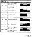
- the prerequisite is the use of an operator who is responsible for tracking the Edge provides an edge strip with the width of only one pixel.
- the first two cases form the normal case, the last case is uncomfortable because no statement about the further course of the edge is possible.
- the corresponding marked cases are shown side by side in Figure 5 (from left to right (UP, Down, NOedge, HORizontal).
- the endpoint is assigned the y-coordinate 0.0, because of the edge image does not show why there is no other pixel.
- the reason can either be that there is a corner of an object (appears in this case the corner somewhat rounded), or the threshold value when generating the edge image was not set small enough (so that the edge continues arbitrarily, however was no longer recognized as such).
- Texture edges are recognizable by the fact that there is an area between the steps exists in which two pixels are superimposed in the edge image.
- Figure 11b Texture edges are not further treated because there is no information in the binary image about the real color gradient at the edge; the result of a new interpolation would always result in a deterioration in appearance have as a consequence.
- two Levels of pixels are placed on top of each other, for example with the one already treated case of two edges tapering to a point. This case is in figure 11c reproduced.
- the cases are generally shown, which to lead "two superimposed pixels" in the edge image. In this case treatment is given anyway.
- By converting the status to NO on the At the end, where the transition area exists both cases can be treated meaningfully.
- both states are corrected to NO, in the case of two Edges, only one status is implemented, the other then still an interpolation.
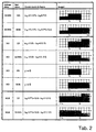
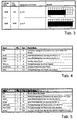
- Noise is expressed in the edge image by the occasional appearance of edge pixels, that have no connection with a real edge. This case is taken into account in Tables 1 to 3 to the extent that if both statuses NO the y value is set to zero and is therefore not dealt with any further.
- the example of an obliquely upward-pointing edge should clarify once again what differences there are between the assumed straight line, and the maximum of the real straight line.
- the real straight line therefore runs safely between the coordinates (0.0) and (1.0) or (x E, 1 ) and (x E + 1.1 ), otherwise a different rasterization would have resulted.
- FIG. 18 shows how the window is shifted by one pixel on the right leads to a new and a deleted level.
- the method works as presented on a point-sampled image
- the final coloring of a pixel results from its point sampled Color by adding the colors of neighboring pixels.
- the admixture of colors is not carried out in every case.
- only an adjacent pixel color is mixed, namely the one to which the color jump existed is only added in exceptional cases of more than two colors.
- the individual mixing factors are determined on the basis of the per pixel created straight line (s), which is determined by the perceptible color jumps in the image become.
- the direction of admixture results from the position of the pixel with respect to the Color jump. For example, there was a color jump to the pixel above a mixed factor with regard to this pixel is determined from this.
- the y value is greater than 0.0, but less than 1.0, the pixel at the Coordinate (0 / 0.5) experience an admixture from the underlying pixel. Is the y value is less than 0.0, but greater than -1.0, so the pixel at the Coordinate (0 / -0.5) mixed with the color value above.
- the amount of The y value specifies how much should be added. Looking at two Special cases should make it clear why this was determined in this way.
- the y value is exact Zero, so the line runs exactly between the two pixels, each pixel belongs so full to the respective color page.
- the y-value is almost 0.5, it belongs upper pixel only 50% of the upper half of the color, but has the color of upper half of the color, since the image was the result of a point sampling process.
- the y value now marks where the actual color jump should have taken place, if vertically a larger resolution would have been chosen. Obtained through the mixture the pixel now has a color due to the areas between the two Extreme colors.
- the second method gives more accurate results. This is due to the location the straight line determines the exact area proportion with respect to the pixel center, which is below the straight line ( Figure 20).
- the Percentage of area below the straight line is the color value of the pixel below added, because then the color jump to the pixel underneath existed. Otherwise is the color of the pixels overlaid.
- the area proportions can be determined using a table lookup, in which only the slope of the straight line and the distance between the straight line and the pixel center comes in.
- the method can therefore be implemented quite well in hardware and thus represents an extension option of the algorithm presented here with which greater accuracy can be achieved, but with greater accuracy Hardware expenditure, since additional tables are required (Figure 21).
- col new center mix center * col old center + mix up * col up + mix down * col down + mix left * col left + mix right * col right
- the window size is variable and not exclusively square Window sizes limited with a centered central pixel, but it is It is possible to define a separate view length for each direction. For example conceivable to choose a larger section horizontally because of the edge information for the pixels is stored on-chip. Should down at Use as few lines as possible in the display process, since all these lines must be saved (explanation in the case described below Hardware implementation).
- the post-antialiasing process was implemented in the programming language C, with particular emphasis on variability.
- Command line parameters can be used between different variants of the algorithm to be switched; not only are all preliminary stages of the final version available, but also various additional test implementations, such as For example, various options for generating edge images via Manhattan distance or square distance.
- the preliminary stages of the final Algorithms were used to compare which quality gains each had built-in features, like tracking multiple levels instead of one, or Use the last stage only half, caused. So it was possible always to be touched up where the visual impression of the antialiases Images left a lot to be desired.
- IsEdgePixel () tests whether the pixel (x, y) as the edge, the pixel (x, y-1) as horizontal or the pixel (x-1, y) is marked as a vertical edge in the edge image; just then a further treatment must take place, otherwise the old color value simply transferred to the new image.
- the function computeMixFactorsHorizontal () is called both for the horizontal mix factors (mix_up and mix_down) and for the vertical (mix_left and mix_right). This is possible because the current edge window is converted using transformVerticalToHorizontal () so that the formerly vertical edges can now be tracked horizontally.
- IsEdge is used to test whether it is at the corresponding point in the edge window there is an edge pixel, only then can an edge be tracked, otherwise the corresponding mixing factor is set to zero.
- In maskRightEdgeType is created from the edge window, which was 4 bits per Contained pixels, the bit hidden by the central pixel of the window is specified so that you can continue working with a binary image from now on.
- With translateWindow () all pixels of the edge window are one pixel behind shifted below, so that in the center is the edge pixel from which the edge should be tracked to get the blending factor for the top pixel.
- mixFactor () ultimately becomes the mix factor determined, which results from the respective edge.
- mixColors the missing mixing factor for the central pixel is first determined, again different variants are provided, and then the actual mixture of the five in question is based on the mixture formula upcoming colors.
- the hardware implementation shown below is an exemplary embodiment which serves primarily to illustrate the execution of the method.
- the address widths for the counters were kept variable, as was the bit width of the mixing factors, just like the table width and length of the dividers used.
- the general public could not be maintained everywhere, otherwise some modules would have become too complex.
- the findSeq () module is to be mentioned in which, starting from an (nxn) window, approximately n2 / 8 pixels are to be considered to ensure tracking of the stages.
- the positions of the register stages had to be set in a special case, since more pipeline stages are necessary with a larger window, because the complexity increases.
- specific bit widths have been specified in the block diagrams of the parameterizable modules.
- the window size is chosen too small (approximately 9 x 9), 50 the image quality remains flat edges leave a lot to be desired since the transition areas become very short (only 8 pixels / compare figure 8). However, if the window is chosen too large, it increases the complexity of some modules, and thus the number of gates, very strongly. For So the implementation was chosen to be a medium window size Find compromise between these two extremes.
- the maximum screen width was assumed to be 2048 pixels per line. This certainly places an upper limit on screen resolutions over the next few years
- the maximum screen height is also fixed at 2048 lines. Since that The ratio of width to height is usually fixed (1.25 or 1.33), see above this maximum value will certainly never be reached.
- the establishment of the maximum screen width led to setting the address widths of the counters 11 bits and the maximum length of the pipes used to 2048 elements.
- the method according to the invention can be used both as a triple buffer and as intermediate module in the display process find application (explanation of configuration options in a later section).
- the design using a triple buffer requires a fairly complex RAM controller that can correspondingly required color values from the memory (SDRAM or another Storage type) fetches, and writes back the mixed values.
- SDRAM or another Storage type the memory
- the design this controller would go beyond the scope of this work, why on this Variant was dispensed with. So the basic system was for the display process designed. By means of small changes, the system can be used for triple buffer operation convert as described in more detail below.
- the system is based on the pipelining principle, ie a ready-mixed pixel is delivered in every cycle. In order to accomplish this, there are always several pixels in the processing at the same time, since it is not possible to carry out all necessary processing steps in one cycle (in our case 15 ns).
- the system works in such a way that with each cycle a new color value of a pixel is adopted and a fixed number of cycles later the mixed color value of this pixel is made available as an initial value.
- the individual register levels have been inserted in such a way that the maximum processing time in one cycle is not exceeded.
- a 66 MHz clock was selected as the clock rate; the period is thus 15 ns.
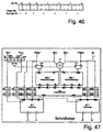
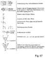
- the individual modules are illustrated by block diagrams, the ones used Symbolism in Figure 67 is explained.
- the modules are here according to the top-down method presented, that is, the main module is described first, then the modules it contains. If a module contains further sub-modules, the corresponding sub-module is immediately connected to the module described.
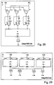
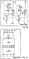
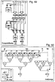
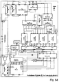
- the antialiase system () according to FIG. 24 and Table 4 is the main module of from which all other modules are imported and further as sub-components are described below.
- the edge generation process must always have a lead of 8 lines and 8 points, so that with one 17 x 17 windows all edge information is already available when it are needed.
- the edge information is stored in the EdgeValueGenerator () module (Table 6, Figure 27) generated from the newly read color values.
- the Windowswitch () module Figure 31
- the current section from the edge image is kept.
- CenterPipe () becomes the edge information that is temporarily no longer required cached. 4 bits of edge information are held per pixel with 16 pixels stored in parallel, a bit width of 64 bits results.
- the important in this module, the edge information is stored "on-chip" because 64 bits are stored in each cycle and 64 bits are also read in again in parallel. An external memory would therefore be constantly busy storing values and to get back, and could not be used for anything else.
- the Saving is practically also possible, as with a maximum screen width of 2048 pixels 128 kB must be stored. (Currently there are on-chip RAMs from 1 Mbit can be implemented without major problems.) This memory is available in both variants (Triple buffer / display process) necessary.
- ColorPipe In ColorPipe () the color values are retained until they are used for the mixture of the new ones Colors are needed again. In CenterPipe () or UpPipe () the Color values delayed by an additional line. The content of the pipes represents as shown in Figure 25.
- the edgecounter () ( Figure 26, Table 5) specifies for which pixel the Edge information is generated. Accordingly, for some pixels Neighbors hidden via the two signals rightValid and downValid, which are in the Image are not real neighbors. rightValid becomes one at the last pixel Line withdrawn because the next pixel already belongs to the next line and thus has nothing in common with the current pixel. downValid will be in the last Row withdrawn because the row below no longer contains valid data. Ready indicates when all pixels of the current image were read. From this Time no longer has to be waited for new data, so that from this Signal the enable signal can be generated for all other modules.
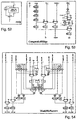
- the EdgeValueGenerator () module ( Figure 27, Table 6) the edge information is generated for every single pixel. Three color values are required for this ( Figure 24 below), of which only two are always taken over. The central one Color value is the right color value of the previous pixel.
- the EdgeDirUnit () modules the decision is made as to whether the current pixel is to be regarded as an edge pixel; the EdgeDirUnit () module defines the type of the edge.
- EdgeDiffUnit () module Figure 28
- the actual decision is made in the EdgeDiffUnit () module ( Figure 28) whether There is an edge between two pixels or not.
- the Euclidean distance a between the two colors can be determined in the color space then a threshold is applied afterwards.
- the threshold (ref) has been executed as a parameter so that it can be easily changed.
- a threshold value of 40.0 is assumed because this value is inherent has proven many test images.
- the value needs in the final hardware implementation not to be fixed, but can be changed again and again if it turns out that for different scenes different Thresholds should be used.
- F Max 3/2- ⁇ 3) / 3/2 ⁇ 13.4% .
- a approx k + 11/32 * l + m / 4 , the maximum error can even be minimized to 8%.
- Due to the much simpler form of the pre-factors in the first variant no multiplication necessary, just a shift operation by two digits to the right), the larger error is accepted.
- a 13% error may sound a lot; however, since the result values are only required for threshold value formation, this is acceptable. Simply mark a few pixels less than the edge as normal. By adjusting the threshold, however, this can be made up for.
- the WindowSwitch () module ( Figure 31, Table 10) is the current edge image section stored, the bits are already stored so that vertical Edges can be tracked horizontally. Via the EdgePipe_out input the already generated edge information of the right column from the memory read; The newly generated edge value is added via EdgeVal. Corresponding EdgePipe_out outputs the edge information required for later lines. The edge values are not saved pixel by pixel in the pipe, but rather sorted according to the types of edge values, so that the Distribution in Figure 32 results.
- the edge information is needed line by line. Because the information column-wise new in the window must be in the horizontal window A reordering of the bits takes place so that they are in the correct order get saved. This does not have to happen with the vertical window. There there is a transformation from vertical to horizontal. In the end the effect of the transformation is reversed by the reordering of the bits made.
- the parameters were not replaced by concrete ones Values replaced so that the pattern of the concatenation of the bits is clearer (w is the width of the edge window, i.e. 17, and h is the height, also 17).
- the module pipe () ( Figure 35, Table 12) is a simple one Delay module that adopts a date and after a predefined one Returns the number of measures. In its basic form, the module would be too implement that as many registers as the Length required. However, this is due to the significant hardware cost (7th Gates per stored bit) not useful, because the length is also variable is not possible at all. A RAM is therefore provided in which the Hardware costs significantly cheaper (maximum 1 gate per stored bit) are. Great care was taken when designing the pipe () the hardware costs are as low as possible, because the pipes are due to their enormous size cause the highest cost. In the normal form of a pipe a dual-port RAM is always necessary, as a value is written in each cycle and a value must be read at the same time. By placing two in parallel Values in memory, the second port could be saved by always in one Clock two values are written simultaneously to one address and in the next Clock two values are read out in parallel ( Figure 37).
- the RAM used now has twice the data width, but only that half length. So the amount of storage remained the same, but it became a cost causing port saved.
- the registers In0 and Out1 are used for parallelization two data or serialization of the data required.
- the Stat contains the read / write signal for the RAM. According to the previous considerations it would only be possible to allow straight lengths for the pipe. By the additional Register DIn are now even odd lengths possible because it is for the delay around another clock provides if it is switched on in the data path.
- the Address counter Adr is incremented after each write operation. Is the length of the Pipe reached, it starts again at address 0; consequently it will RAM operated as a ring buffer.
- a reset signal is used, through which an initialization phase is thrown, which clears the RAM content.
- n clocks there are accordingly n clocks required. During this time, the data at the DIn input are ignored.
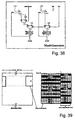
- the edge window is continuously changed by one during processing Pixel moved to the right. If the last pixel of an image line is reached, then a jump is made to the first pixel of the next line. Because of this Procedures arise for the last eight pixels of a line on the right edge of the Window pixels that actually already belong to the left edge of the image (see figure 39). Accordingly, there are still values in the window for the first eight pixels of a line included, which actually belong to the right edge of the image. To the each for To hide the current window of invalid values, the x mask is required. Because in the unmasked window both pixels from the right and from the left edge of the image may be included when switching to the next one Line wasted no time and treatment as normal can take place.
- the x-mask generation now runs in such a way that the last mask rotates with every cycle shifted one place to the left (just like the pixels in the edge window). At the a new value is adopted on the right edge, which indicates whether the pixel column is still belongs to the same line.
- the last pixel of a line has been processed (indicated by the EndOfLine signal), the mask is inverted bit by bit, which automatically creates the mask for the first pixel of the new line. Accordingly, the y mask is advanced by one value for each new line.
- the position of the current is processing pixels determined.
- the variables x_in and y_in determine whether this is new in the edge window visible pixels belongs to the surroundings of the current pixel.
- the signal EndOfLine is activated at the end of a line to toggle the xmask in the Enable MaskGenerator () module.
- the CutNeededWindow () submodule therefore has no independent functionality.
- MaskNeededWindow () then does not actually mask the more rectangular window, in which the pixels are hidden that are not used current environment.
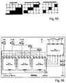
- the edge window becomes the Extracted start and end point of the tracked line.
- the FindEnd () module (Table 18) the central stage is followed in both directions to the end. At the ends are the states that indicate in which directions further possible levels are.
- GetBestStat () Figure 45, Table 19
- the hidden the best possible status In the SortSections () module, the edge window divided into four sectors (again no real module, only selection of the Bits), whereupon, based on the best possible status to the right and left Sector is selected in which further levels are suspected.
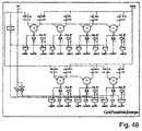
- findSeq () (Table 22) are all possible further levels in the corresponding sector tracked.
- SelectJumps () (Table 23, Figure 47) is ultimately used for all possible levels only select the levels through which a straight line really can be interpolated. The sign of the y values is then based on the status customized.
- the central level is tracked to the end. In principle is this is an iterative process, because at every point (starting from the middle) there is a Compare whether the stage has already ended. If this is the case, the status is on determines this position, otherwise the same occurs at the next position Procedure. However, since this (discretely built) takes too long this module was modeled as a single "case" in which the query takes place in parallel. Through automatic logic optimization using a Suitable tools were the hardware costs and the processing time reduced.
- both up and down offers another level of tracking down. Based on each opposite status at the end of the stage, the best option is selected. If no level is appropriate, the corresponding status is set to NO corrected.
- the findSeq () module further possible levels determined. If each step is only one pixel long, the result is there is a 45 ° slope, and a maximum of seven further steps can be completed to fit the sector. Accordingly, jumps into seven separate areas subdivided in which the length of the respective stages is stored.
- the last stages can no longer be that long, their bit width is reduced to two or reduced one bit. (They can’t be so long because when they’re at fifth level something should be entered, the previous levels at least must have had length one. Hence the fifth stage can still have a maximum length of three so that it is still completely in the window and is recognized.)
- the procedure in the findSeq () module can best be written iteratively: actual If there is no further edge pixel in a line, the length of the step becomes the corresponding position in the result, and in the line above again tries to find another edge pixel. Is not another level completely contained in the window, so the corresponding length is in the result Set to zero.
- the first SelectFirstOne () module is used to decide whether at one longer or one shorter levels than the central level. The The decision is based on the level closest to the central level and has a different length. Using the second SelectFirstOne () module will decide which of the two possible step lengths multiple times May occur because of the rasterization rules for a normal straight line may only occur one step length several times in succession. In the MaskEnd () modules Finally, all levels that are hidden by previous masking actions are no longer connected to the central stage. The SelectFirstOne () module was used again just like the MaskEnd () module a case statement modeled and minimized by Synopsys.
- AddJumps () module Figure 50, Table 26
- the mask is a bit mask that specifies which of the step lengths in jumps should be included. As already described, the last stage is only with half the length and height are taken into account.
- the module ComputeMixFactor () ( Figure 51, Table 27) will now be described become.
- the just determined y-value yReal inverted or not (multiplexer bottom left), so that the y-value is now 1: 1 the Mixing factor in the range 0..1 corresponds.
- the mixing factor is only cut to the range 0..1 so that none Overflows arise. Deciding whether the pixel is above or below the Color jump is processed, is already determined by using the module.
- the third to last multiplexer thus only selects alternative branches that have one Parameters are selected.
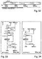
- the reciprocal formation (module Recip (), Figure 52, Table 28) is used for this simple case attributed to a table lookup.
- the input value serves here as address for a ROM access, in which the reciprocal value is returned as a result.
- the mixing factors previously calculated were always based on only one Straight lines determined. To get a more global impression and thus the The module determines the best possible mixing factors for a pixel MaskMixFactor () looks at all four lines and, if necessary, some Mixed factors still masked out. The need arises from noise, which results from using the difference operator as an edge detector (any other edge operator would produce noise in some way).
- edge detector any other edge operator would produce noise in some way.
- the actual color of the pixel is due to its original color and Colors of the four neighbors determined. For this purpose, the required Colors loaded, whereby the right color as the central color of the next pixel and left color of the next but one pixel acts.
- ComputeCenterFactor the missing mixing factor for the central pixel is determined, whereupon in Mixing_channel () of the Mixing () module ( Figure 56, Table 31) actual color mixing takes place per color channel.
- the final mixture of colors takes place according to the mixture formula in the module Mixing_Channel () ( Figure 58, Table 33) instead. According to what may be necessary Division by two, a rounding takes place with which the accuracy is still a bit can be increased, which is followed by an overflow interception.
- the image stored in the frame buffer is transferred via the RAMDAC converted into analog signals that the monitor needs to display the image.
- There a finished picture is not always in the frame buffer because the rasterized pixels would only be filed gradually if you would See the structure of each individual picture (the frame buffer is placed in front of each picture deleted).
- the double buffer technique is used used.
- the rasterizer works on one frame buffer while the The content of the other frame buffer is displayed on the monitor. Is the next When the image is rendered, it is switched between the two buffers and them exchange their functions. The display of an image has ended before the next picture has been rendered, the previous picture is again displayed.
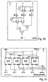
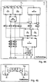
- Figure 59 contains a possible system configuration on the left:
- the renderer sends the Color values of the rasterized pixels and further information (x, y position, z value for z-buffering) to both frame buffers, only one of which contains the values in the Memory takes over.
- the content of the other frame buffer is sent to the RAMDAC transfer.
- To ensure the highest possible refresh rate, i.e. to Avoiding image flicker is usually not just one pixel per clock RAMDAC transferred, but two or four; so the clock rate can be outside of the chip can be kept small and still achieve a high transfer rate become.
- the pixels are then serialized again in the RAMDAC and with a correspondingly multiple clock rate sent to the monitor.
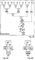
- the double buffer method described above can be applied to a triple buffer can be expanded, whereby the content of a frame buffer is displayed on the monitor the second is processed using post-antialiasing, and the third Framebuffer the next image is already generated by the renderer.
- This The process is indicated schematically in FIG. 62 as a cycle.
- FIG. 63 As a block diagram is a triple buffer is shown in FIG. 63. Three frame buffers are connected in parallel and receive their signals in cyclical exchange or give them accordingly.
- the time required for the individual processes is very different. Requires about that The rendering process takes about 1/80-second to display an image Usually at least 1/30 second. The time for antialiasing the picture is going to be move somewhere between these two extreme values.
- the process waits for completion of the next image by the renderer. If the next picture is available, so the previous renderer frame buffer takes over the function of antialiasing.
- the renderer process If the renderer process is finished with the generation of a new image, then immediately switched to the original display buffer, where immediately with the Editing of a new picture can be started.
- the renderer process must never wait for the display process, because due to the already described Transfer the display of the image to the antialiasing buffer has been.
- the memory interface is usually dimensioned so that not only one Pixel per clock is transferred from memory, but several in parallel Up to 4 pixels can be transmitted in parallel.
- the essential prerequisite for ensuring such transmission rates is an efficient memory mapping so that the next one as quickly as possible required pixels can be accessed.
- the storage organization is an example mentioned in the frame buffer of a known system (GMD VISA).
- the SDRAM memory (1 Mx32 organization) used is physically in two banks divided, which are made up of Rows (2048), which in turn are divided into columns (256 / there is one pixel in each column). Is within a row it is possible to access any column address in one cycle, whereas switching the individual rows takes 7 bars.
- the Memory mapping was so designed that the number of row changes both in the rendering process as well as in the readout for the display process is minimized.
- In order to save another address bus one address Always 2 neighboring pixels fetched from memory at the same time, since 2 memory chips be available.
- the rows were now subdivided so that there was an area in them of 32 x 16 double pixels, and thus each within this area Double pixels can be read out in one cycle (FIG. 65).
- the EdgeReadFIFO () is dimensioned so that it is never empty, so that can always be worked on.
- the mixing factors coming out of MaskMixFactor () are calculated using the Module cmp () checks to see which of the mixing factors is non-zero. If this is not the case with none, the current pixel does not have to be mixed and the mix factors are discarded. However, at least one of the Factors not equal to zero, they are added together with the current pixel number the MixFactorFIFO () saved for later use (once the color values are off memory) for the actual mixing. Based on the mix factors, the required ones are then in the RequestFIFO () Color requests cached. For neighboring pixels, under Circumstances need the same color values, so these double requirements be sorted out.
- the embodiment of the invention is not limited to the above specified preferred embodiments. Rather is a number of Variants possible, which of the solution shown also in principle makes use of different types.
Landscapes
- Physics & Mathematics (AREA)
- Engineering & Computer Science (AREA)
- Geometry (AREA)
- Computer Graphics (AREA)
- General Physics & Mathematics (AREA)
- Theoretical Computer Science (AREA)
- Image Generation (AREA)
- Controls And Circuits For Display Device (AREA)
Applications Claiming Priority (2)
| Application Number | Priority Date | Filing Date | Title |
|---|---|---|---|
| DE19840529 | 1998-08-30 | ||
| DE19840529 | 1998-08-30 |
Publications (3)
| Publication Number | Publication Date |
|---|---|
| EP0984397A2 true EP0984397A2 (fr) | 2000-03-08 |
| EP0984397A3 EP0984397A3 (fr) | 2002-04-17 |
| EP0984397B1 EP0984397B1 (fr) | 2005-03-02 |
Family
ID=7879904
Family Applications (1)
| Application Number | Title | Priority Date | Filing Date |
|---|---|---|---|
| EP99250266A Expired - Lifetime EP0984397B1 (fr) | 1998-08-30 | 1999-08-06 | Methode et dispositif pour eliminer les marches indesirees dans un affichage a balayage lignes |
Country Status (3)
| Country | Link |
|---|---|
| US (1) | US6982723B1 (fr) |
| EP (1) | EP0984397B1 (fr) |
| DE (1) | DE59911685D1 (fr) |
Cited By (1)
| Publication number | Priority date | Publication date | Assignee | Title |
|---|---|---|---|---|
| CN112017101A (zh) * | 2019-05-31 | 2020-12-01 | 苹果公司 | 可变光栅化率 |
Families Citing this family (31)
| Publication number | Priority date | Publication date | Assignee | Title |
|---|---|---|---|---|
| US7663642B2 (en) * | 2000-11-15 | 2010-02-16 | Sony Corporation | Systems and methods for rendering a polygon in an image to be displayed |
| JP4144374B2 (ja) * | 2003-02-25 | 2008-09-03 | ソニー株式会社 | 画像処理装置および方法、記録媒体、並びにプログラム |
| JP2005100177A (ja) * | 2003-09-25 | 2005-04-14 | Sony Corp | 画像処理装置およびその方法 |
| US7333673B2 (en) * | 2003-10-30 | 2008-02-19 | Samsung Electronics Co., Ltd. | Method and apparatus for image detail enhancement without zigzagged edge artifact |
| US7263229B2 (en) * | 2003-10-30 | 2007-08-28 | Samsung Electronics Co., Ltd. | Method and apparatus for detecting the location and luminance transition range of slant image edges |
| TWI228240B (en) * | 2003-11-25 | 2005-02-21 | Benq Corp | Image processing method for reducing jaggy-effect |
| US7330592B2 (en) * | 2004-01-27 | 2008-02-12 | Samsung Electronics Co., Ltd. | Method and apparatus for detecting the location and luminance transition range of slant image edges |
| US8744184B2 (en) * | 2004-10-22 | 2014-06-03 | Autodesk, Inc. | Graphics processing method and system |
| JP4180043B2 (ja) * | 2004-11-15 | 2008-11-12 | シャープ株式会社 | 3次元図形描画処理装置、画像表示装置、3次元図形描画処理方法、これをコンピュータに実行させるための制御プログラムおよび、これを記録したコンピュータ読み取り可能な可読記録媒体 |
| KR100698626B1 (ko) * | 2004-12-10 | 2007-03-21 | 삼성전자주식회사 | 에일리어싱을 방지하기 위한 영상 보간 장치 및 방법 |
| US7256785B1 (en) * | 2005-04-19 | 2007-08-14 | Adobe Systems Incorporated | Assigning subpath attributes in a drawing |
| US7502028B1 (en) * | 2005-04-19 | 2009-03-10 | Adobe Systems Incorporated | Assigning region attributes in a drawing |
| US7646386B2 (en) * | 2005-04-19 | 2010-01-12 | Adobe Systems Incorporated | Modifying a path in a drawing |
| JP4623290B2 (ja) * | 2005-07-01 | 2011-02-02 | 富士ゼロックス株式会社 | 画像処理装置および画像処理方法、画像処理プログラム、記憶媒体 |
| US7616203B1 (en) * | 2006-01-20 | 2009-11-10 | Adobe Systems Incorporated | Assigning attributes to regions across frames |
| JP4723427B2 (ja) * | 2006-06-30 | 2011-07-13 | ルネサスエレクトロニクス株式会社 | 画像処理回路および画像処理システムならびに画像処理方法 |
| US7876332B1 (en) | 2006-12-20 | 2011-01-25 | Nvidia Corporation | Shader that conditionally updates a framebuffer in a computer graphics system |
| US8547395B1 (en) * | 2006-12-20 | 2013-10-01 | Nvidia Corporation | Writing coverage information to a framebuffer in a computer graphics system |
| US7817165B1 (en) | 2006-12-20 | 2010-10-19 | Nvidia Corporation | Selecting real sample locations for ownership of virtual sample locations in a computer graphics system |
| US7864193B2 (en) * | 2007-07-02 | 2011-01-04 | International Business Machines Corporation | RGB color conversion palettes |
| US8004522B1 (en) | 2007-08-07 | 2011-08-23 | Nvidia Corporation | Using coverage information in computer graphics |
| US8325203B1 (en) | 2007-08-15 | 2012-12-04 | Nvidia Corporation | Optimal caching for virtual coverage antialiasing |
| US8294730B2 (en) * | 2007-09-04 | 2012-10-23 | Apple Inc. | Anti-aliasing of a graphical object |
| KR20100079037A (ko) * | 2008-12-30 | 2010-07-08 | 삼성전자주식회사 | 비디오 영상 부호화 방법 및 장치 |
| TWI493500B (zh) * | 2009-06-18 | 2015-07-21 | Mstar Semiconductor Inc | 使二維影像呈現出三維效果之影像處理方法及相關影像處理裝置 |
| US10354415B2 (en) * | 2017-09-11 | 2019-07-16 | Autodesk, Inc. | Method and apparatus for a seamless texture unit generator |
| JP7119682B2 (ja) * | 2018-07-17 | 2022-08-17 | 京セラドキュメントソリューションズ株式会社 | 画像処理装置及び画像処理プログラム |
| KR102552299B1 (ko) * | 2018-08-31 | 2023-07-10 | 삼성디스플레이 주식회사 | 잔상 보상부, 이를 포함하는 표시 장치, 및 표시 장치의 구동 방법 |
| CN109657328B (zh) * | 2018-12-12 | 2023-03-14 | 中国航空工业集团公司西安航空计算技术研究所 | 一种面向gpu硬件线光栅化边界算法的tlm微结构 |
| CN110059625B (zh) * | 2019-04-18 | 2023-04-07 | 重庆大学 | 一种基于mixup的人脸训练与识别方法 |
| CN116862756B (zh) * | 2023-09-05 | 2023-12-19 | 广东匠芯创科技有限公司 | 行数据处理方法、行缓存器、电子设备及存储介质 |
Family Cites Families (20)
| Publication number | Priority date | Publication date | Assignee | Title |
|---|---|---|---|---|
| US4835532A (en) * | 1982-07-30 | 1989-05-30 | Honeywell Inc. | Nonaliasing real-time spatial transform image processing system |
| US4704605A (en) * | 1984-12-17 | 1987-11-03 | Edelson Steven D | Method and apparatus for providing anti-aliased edges in pixel-mapped computer graphics |
| JP3071229B2 (ja) * | 1990-04-09 | 2000-07-31 | 株式会社リコー | 図形処理装置 |
| US5140315A (en) * | 1990-04-16 | 1992-08-18 | Analog Devices, Inc. | Antialiased pixel based display system for lines and solids |
| US5029108A (en) * | 1990-09-24 | 1991-07-02 | Destiny Technology Corporation | Edge enhancement method and apparatus for dot matrix devices |
| US5264838A (en) | 1991-08-29 | 1993-11-23 | Honeywell Inc. | Apparatus for generating an anti-aliased display image halo |
| JPH05346953A (ja) * | 1992-06-15 | 1993-12-27 | Matsushita Electric Ind Co Ltd | 画像データ処理装置 |
| JP3223617B2 (ja) * | 1992-11-30 | 2001-10-29 | 富士ゼロックス株式会社 | 描画装置及び描画方法 |
| US5625768A (en) * | 1994-05-23 | 1997-04-29 | Cirrus Logic, Inc. | Method and apparatus for correcting errors in pixel characteristics when interpolating polygons into a pixel grid |
| US5668940A (en) * | 1994-08-19 | 1997-09-16 | Martin Marietta Corporation | Method and apparatus for anti-aliasing polygon edges in a computer imaging system |
| JP2755204B2 (ja) * | 1995-02-23 | 1998-05-20 | 日本電気株式会社 | 多面体表示方法および多面体表示装置 |
| JP3609189B2 (ja) * | 1995-03-14 | 2005-01-12 | 株式会社リコー | アンチエイリアシング機能を有する画像生成装置 |
| US5748178A (en) | 1995-07-18 | 1998-05-05 | Sybase, Inc. | Digital video system and methods for efficient rendering of superimposed vector graphics |
| US5742277A (en) * | 1995-10-06 | 1998-04-21 | Silicon Graphics, Inc. | Antialiasing of silhouette edges |
| US5940080A (en) * | 1996-09-12 | 1999-08-17 | Macromedia, Inc. | Method and apparatus for displaying anti-aliased text |
| US6339479B1 (en) * | 1996-11-22 | 2002-01-15 | Sony Corporation | Video processing apparatus for processing pixel for generating high-picture-quality image, method thereof, and video printer to which they are applied |
| US6229521B1 (en) * | 1997-04-10 | 2001-05-08 | Sun Microsystems, Inc. | Method for antialiasing fonts for television display |
| US6034700A (en) * | 1998-01-23 | 2000-03-07 | Xerox Corporation | Efficient run-based anti-aliasing |
| US6310970B1 (en) * | 1998-06-24 | 2001-10-30 | Colorcom, Ltd. | Defining surfaces in border string sequences representing a raster image |
| US6226400B1 (en) * | 1998-06-24 | 2001-05-01 | Colorcom, Ltd. | Defining color borders in a raster image by identifying and breaking contrast ties |
-
1999
- 1999-08-06 DE DE59911685T patent/DE59911685D1/de not_active Expired - Lifetime
- 1999-08-06 EP EP99250266A patent/EP0984397B1/fr not_active Expired - Lifetime
- 1999-08-30 US US09/385,822 patent/US6982723B1/en not_active Expired - Fee Related
Cited By (1)
| Publication number | Priority date | Publication date | Assignee | Title |
|---|---|---|---|---|
| CN112017101A (zh) * | 2019-05-31 | 2020-12-01 | 苹果公司 | 可变光栅化率 |
Also Published As
| Publication number | Publication date |
|---|---|
| EP0984397B1 (fr) | 2005-03-02 |
| EP0984397A3 (fr) | 2002-04-17 |
| US6982723B1 (en) | 2006-01-03 |
| DE59911685D1 (de) | 2005-04-07 |
Similar Documents
| Publication | Publication Date | Title |
|---|---|---|
| EP0984397B1 (fr) | Methode et dispositif pour eliminer les marches indesirees dans un affichage a balayage lignes | |
| EP1175663B1 (fr) | Procede de conversion d'un element de base graphique en une serie de points | |
| DE69424716T2 (de) | Verfahren und Vorrichtung zur adaptiven Steuerung der Texturabbildung | |
| DE69636599T2 (de) | Verfahren und system zur wiedergabe von grafischen objekten durch teilung in bildstücke und zusammensetzen von bildlagen zu einem wiedergabebild | |
| DE69836924T2 (de) | Block- und bandorientierter durchlauf in dreidimensionaler dreieckswiedergabe | |
| DE69917799T2 (de) | Texturierungssysteme zur verwendung in drei-dimensionalen abbildungssystemen | |
| DE69130132T2 (de) | Verfahren zur Erzeugung von Adressen zu texturierten, in RIP Maps gespeicherten graphischen Primitiven | |
| DE60000686T2 (de) | Graphisches system mit super-abgetastetem musterpuffer mit erzeugung von ausgangpixeln unter verwendung von selektiven adjustierung der filterung zur artifaktverminderung | |
| DE60311359T2 (de) | Vorrichtungen und Verfahren zur kontrollierbaren Texturabtastung | |
| DE68927471T2 (de) | Verfahren zur Schattierung eines graphischen Bildes | |
| DE69610341T2 (de) | 3-D-Bildertexturierung und -schattierung | |
| DE10296401B4 (de) | Verbund-Rendering von 3-D-Graphikobjekten | |
| DE69602728T2 (de) | Vorrichtung zur bildmanipulation und -generation | |
| DE3854543T2 (de) | Prioritätsverwaltung eines Tiefendatenpuffers für Echtzeitrechnersysteme zur Bilderzeugung. | |
| DE3855231T2 (de) | Prioritätsauflösungssystem zwischen Polygonen mit Antialiasing | |
| DE69811849T2 (de) | Verfahren und gerät zur interpolation von attributen bei 3d-grafiken | |
| DE60000447T2 (de) | Graphisches system das muster in einem musterpuffer darstellt und in anhängigkeit von gespeicherten mustern pixel erzeugt | |
| DE112018004343T5 (de) | Mehrraum-rendering mit konfigurierbaren transformationsparametern | |
| DE102015113240A1 (de) | System, verfahren und computerprogrammprodukt für schattierung unter verwendung eines dynamischen objektraumgitters | |
| DE602004003111T2 (de) | Tiefen-basiertes Antialiasing | |
| DE19708679A1 (de) | Bilddarstellungsverfahren und Vorrichtung zur Durchführung des Verfahrens | |
| DE102005050846A1 (de) | Perspektiveneditierwerkzeuge für 2-D Bilder | |
| DE69130127T2 (de) | System und Verfahren zur Farbbilderanzeige | |
| DE60008867T2 (de) | Antialiasingverfahren und -anordnung zur effizienten nutzung von wenigen mischeinheiten | |
| DE102011011641A1 (de) | System, Verfahren und Computerprogrammprodukt zum Wiedergeben von Pixeln mit zumindest einer halbtransparenten Oberfläche |
Legal Events
| Date | Code | Title | Description |
|---|---|---|---|
| PUAI | Public reference made under article 153(3) epc to a published international application that has entered the european phase |
Free format text: ORIGINAL CODE: 0009012 |
|
| AK | Designated contracting states |
Kind code of ref document: A2 Designated state(s): AT BE CH CY DE DK ES FI FR GB GR IE IT LI LU MC NL PT SE |
|
| AX | Request for extension of the european patent |
Free format text: AL;LT;LV;MK;RO;SI |
|
| PUAL | Search report despatched |
Free format text: ORIGINAL CODE: 0009013 |
|
| AK | Designated contracting states |
Kind code of ref document: A3 Designated state(s): AT BE CH CY DE DK ES FI FR GB GR IE IT LI LU MC NL PT SE |
|
| AX | Request for extension of the european patent |
Free format text: AL;LT;LV;MK;RO;SI |
|
| 17P | Request for examination filed |
Effective date: 20021017 |
|
| AKX | Designation fees paid |
Free format text: AT BE CH CY DE DK ES FI FR GB GR IE IT LI LU MC NL PT SE |
|
| RBV | Designated contracting states (corrected) |
Designated state(s): DE |
|
| GRAP | Despatch of communication of intention to grant a patent |
Free format text: ORIGINAL CODE: EPIDOSNIGR1 |
|
| GRAS | Grant fee paid |
Free format text: ORIGINAL CODE: EPIDOSNIGR3 |
|
| GRAA | (expected) grant |
Free format text: ORIGINAL CODE: 0009210 |
|
| AK | Designated contracting states |
Kind code of ref document: B1 Designated state(s): DE |
|
| REG | Reference to a national code |
Ref country code: IE Ref legal event code: FG4D Free format text: GERMAN |
|
| REF | Corresponds to: |
Ref document number: 59911685 Country of ref document: DE Date of ref document: 20050407 Kind code of ref document: P |
|
| PLBE | No opposition filed within time limit |
Free format text: ORIGINAL CODE: 0009261 |
|
| STAA | Information on the status of an ep patent application or granted ep patent |
Free format text: STATUS: NO OPPOSITION FILED WITHIN TIME LIMIT |
|
| 26N | No opposition filed |
Effective date: 20051205 |
|
| PGFP | Annual fee paid to national office [announced via postgrant information from national office to epo] |
Ref country code: DE Payment date: 20130823 Year of fee payment: 15 |
|
| REG | Reference to a national code |
Ref country code: DE Ref legal event code: R119 Ref document number: 59911685 Country of ref document: DE |
|
| REG | Reference to a national code |
Ref country code: DE Ref legal event code: R119 Ref document number: 59911685 Country of ref document: DE Effective date: 20150303 |
|
| PG25 | Lapsed in a contracting state [announced via postgrant information from national office to epo] |
Ref country code: DE Free format text: LAPSE BECAUSE OF NON-PAYMENT OF DUE FEES Effective date: 20150303 |