EP0984452A2 - Verriegelungsmechanismus - Google Patents
Verriegelungsmechanismus Download PDFInfo
- Publication number
- EP0984452A2 EP0984452A2 EP99306582A EP99306582A EP0984452A2 EP 0984452 A2 EP0984452 A2 EP 0984452A2 EP 99306582 A EP99306582 A EP 99306582A EP 99306582 A EP99306582 A EP 99306582A EP 0984452 A2 EP0984452 A2 EP 0984452A2
- Authority
- EP
- European Patent Office
- Prior art keywords
- drive module
- pin
- drive
- electronic device
- disk drive
- Prior art date
- Legal status (The legal status is an assumption and is not a legal conclusion. Google has not performed a legal analysis and makes no representation as to the accuracy of the status listed.)
- Granted
Links
Images


Classifications
-
- G—PHYSICS
- G11—INFORMATION STORAGE
- G11B—INFORMATION STORAGE BASED ON RELATIVE MOVEMENT BETWEEN RECORD CARRIER AND TRANSDUCER
- G11B33/00—Constructional parts, details or accessories not provided for in the other groups of this subclass
- G11B33/12—Disposition of constructional parts in the apparatus, e.g. of power supply, of modules
- G11B33/121—Disposition of constructional parts in the apparatus, e.g. of power supply, of modules the apparatus comprising a single recording/reproducing device
- G11B33/123—Mounting arrangements of constructional parts onto a chassis
- G11B33/124—Mounting arrangements of constructional parts onto a chassis of the single recording/reproducing device, e.g. disk drive, onto a chassis
-
- G—PHYSICS
- G11—INFORMATION STORAGE
- G11B—INFORMATION STORAGE BASED ON RELATIVE MOVEMENT BETWEEN RECORD CARRIER AND TRANSDUCER
- G11B33/00—Constructional parts, details or accessories not provided for in the other groups of this subclass
- G11B33/14—Reducing influence of physical parameters, e.g. temperature change, moisture, dust
- G11B33/1493—Electro-Magnetic Interference [EMI] or Radio Frequency Interference [RFI] shielding; grounding of static charges
-
- Y—GENERAL TAGGING OF NEW TECHNOLOGICAL DEVELOPMENTS; GENERAL TAGGING OF CROSS-SECTIONAL TECHNOLOGIES SPANNING OVER SEVERAL SECTIONS OF THE IPC; TECHNICAL SUBJECTS COVERED BY FORMER USPC CROSS-REFERENCE ART COLLECTIONS [XRACs] AND DIGESTS
- Y10—TECHNICAL SUBJECTS COVERED BY FORMER USPC
- Y10T—TECHNICAL SUBJECTS COVERED BY FORMER US CLASSIFICATION
- Y10T292/00—Closure fasteners
- Y10T292/42—Rigid engaging means
-
- Y—GENERAL TAGGING OF NEW TECHNOLOGICAL DEVELOPMENTS; GENERAL TAGGING OF CROSS-SECTIONAL TECHNOLOGIES SPANNING OVER SEVERAL SECTIONS OF THE IPC; TECHNICAL SUBJECTS COVERED BY FORMER USPC CROSS-REFERENCE ART COLLECTIONS [XRACs] AND DIGESTS
- Y10—TECHNICAL SUBJECTS COVERED BY FORMER USPC
- Y10T—TECHNICAL SUBJECTS COVERED BY FORMER US CLASSIFICATION
- Y10T292/00—Closure fasteners
- Y10T292/42—Rigid engaging means
- Y10T292/432—Sliding catch
Definitions
- This invention relates to the mounting of disk drives in electronic apparatus, and more particularly but not exclusively to a drive module and releasable self-locking latch mechanism which permits easy and secure insertion and removal of a hard drive with respect to a notebook computer with a minimal risk of damage to the drive or computer.
- the hard disk drive is one of the most frequently serviced, as well.
- the ability to easily remove and replace the hard disk drive enhances the serviceability of a notebook PC. For example, a readily removable hard drive would allow a company to issue each employee a personal hard drive and share fewer notebooks within the organisation.
- Prior techniques for installing a notebook hard drive include mounting the hard drive to a rigid plate with screws. This assembly is then mounted behind a panel on the exterior of the notebook and affixed with additional screws. A separate cable assembly is used to connect the drive to the notebook electronics. Shortcomings of this approach include a difficult installation/removal process requiring a screwdriver and several small screws which can easily be lost by the user. If any of these screws are lost, the hard drive may not be securely installed, which can contribute to early drive failure. Also, the proper alignment and engagement of the interconnection cable is difficult to perform and can contribute to apparent drive failure.
- Another installation approach is to package the hard drive in an enclosure which also serves to properly mount and connect the interconnection cable.
- This assembly is inserted into an opening in the notebook with the cable connector leading until it engages its mating connector on the notebook electronics.
- An openable/removable door on the notebook exterior conceals the drive assembly.
- a small pull tab or handle is incorporated in the drive assembly on the end opposite the cable connector.
- the small size of the pull handle which must be contained behind the door on the notebook exterior, makes it difficult for users with large or weak fingers to grasp the handle.
- the hard drive connector since there are many separate electrical signals which must be relayed through the hard drive assembly connector and the notebook, the hard drive connector has many pins and requires significant force to engage or disengage it from the notebook connector.
- the connector often releases suddenly and in an uncontrolled manner, posing greater risk to the hard drive.
- a latching mechanism connected to an electronic apparatus, for enabling the electronic apparatus to engage with an engaging portion of a disk drive detachably mounted to the electronic apparatus, comprising: a first receiving portion engaging with the engaging portion in a case where the disk drive is inserted in the electronic apparatus and locking the disk drive in the electronic apparatus; a second receiving portion engaging with the engaging portion in a case where the disk drive is released from the electronic apparatus and supporting the disk drive in a position such that a part of the disk drive projects from said electronic apparatus; a movement portion, connected to the first and second receiving portions, being movable so that the first and second receiving portion can engage with the engaging portion of the disk drive.
- an apparatus for easily and securely inserting a disk drive into, and removing it from, an electronic device comprising: a drive module adapted to fixedly receive a disk drive, the drive module being insertable into the electronic device and fixedly carrying thereon a pin extending therefrom in a direction substantially perpendicular to the direction of insertion; a releasable latching mechanism including a latching cam mounted on the electronic device for resilient movement in a direction substantially perpendicular to both the insertion direction and the pin, the latching cam being positioned to engage the pin during insertion of the drive module into the electronic device; the latching cam being arranged to capture and lock the pin when the drive module is fully inserted, to push the pin in a direction to remove the drive module from the electronic device when the latching cam is moved, and to support the drive module in a partly removed position with further movement of the latching cam.
- An embodiment of the present invention addresses the deficiencies of the prior art by providing a drive module with a flanged chassis that carries a hard drive and a hard drive connector.
- the chassis includes a flange which engages the computer and aligns the chassis with respect to the computer.
- the drive module is pivotable about the flange and has a pin which engages a latch on the computer when the hard drive is fully inserted.
- the latch has a cam with an innovative shape which engages the pin so that when the latch is opened, the connectors are first gently but positively disengaged, and the module is then held by gravity and/or by a detent in a static, extended position from which it can be conveniently grasped and removed. When the drive module is fully removed from the computer, the latch returns to a static position which aligns it to receive the pin during a subsequent reinsertion of the drive module.
- a possible deleterious torque about the axis of the pin due to uneven disengagement friction of the connectors is avoided by using two pins positioned side by side and arranged to engage a latch with two identical side-by-side cam configurations.
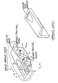
- Fig. 1 is an exploded perspective view of the separate components of the drive module of an embodiment.
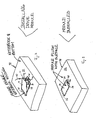
- Fig. 2 is a perspective view of a notebook computer with the inventive drive module partly installed.
- Fig. 3 is a perspective view of a notebook computer with the inventive drive module fully installed.
- Fig. 4 is a perspective view of the latch assembly which is part of an embodiment of the present invention.
- Fig. 5 is a front elevation view of the latch and pin prior to insertion of the Fig. 4 drive module.
- Fig. 6 is a front elevation view of the latch and pin during insertion of the drive module.
- Fig. 7 is a front elevation view of the latch and pin with the drive module fully inserted and latched.
- Fig. 8 is a front elevation view of the latch and pin during the disengagement of the drive module.
- Fig. 9 is a front elevation view of the latch and pin in the disengaged position, with the drive module held ready for removal.
- Fig. 10 is an elevation view illustrating the removal movement of the latch and pin.
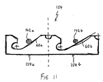
- Fig. 11 is an elevation view of an alternative embodiment of the latch for use with a pair of pins.
- Fig. 1 shows the drive module 10 of an embodiment in exploded form.
- a hard drive 12 is mounted on a chassis 14 by shock mount hardware 16 to protect the hard drive 12 during handling.
- a metal enclosure 18 surrounds the drive 12 and shields it from stray electromagnetic interference (EMI).
- a flexible relay cable assembly 22 carries a horizontally extending relay connector 24 that plugs into the connector 26 of the hard drive 12, and a vertically extending notebook connector 28 which plugs into a mating connector 64 (Figs. 5-10) mounted in the body of the notebook computer 38 (Figs. 2 and 3).
- the module 10 is inserted into the underside of the notebook computer 38 through an opening 30 in the base plate 32 of the computer.
- a retaining flange 34 engages the inside of the base plate 32 outwardly of the opening 30, while the perimeter portions or side flanges 36 of the chassis 14 lie against the outside of the base plate 32 when the module 10 is fully inserted.
- Figs. 2 and 3 illustrate the process of inserting the drive module 10.
- the computer 38 is shown upside down as it would be for the installation of the module 10.
- the retaining flange 34 is first inserted through the opening 30 with the module 10 positioned at an angle to the base plate 32. Then, the module 10 is rotated in the direction of the arrow 40 until the latch assembly 44 and the chassis 14 lie flat against the base plate 32 (Fig. 3).
- Fig. 4 is a perspective view of the latch assembly 44 as seen from the hard drive.
- the latch assembly 44 includes a bracket 46 with a finger recess 48 that can be pushed in the direction of arrow 49, against the bias of a spring 50, in a slot 52 formed in the base plate 32.
- the bracket 46 carries on its side a latching cam 54 which is positioned to engage the pin 42 (Fig. 2) of the drive module 10 when the drive module 10 is inserted into the computer 38.
- the latching cam 54 has a lead-in ramp 56, a latching bay 58, a disengaging ramp 60, and a holding detent 62.
- FIG. 5-9 The action of the latching assembly 44 is illustrated in Figs. 5-9.
- the connector 28 on the drive module 10 and the fixed connector 64 mounted on the notebook computer 38 are shown symbolically in their relative vertical positions to illustrate their engagement and disengagement, although they would not actually be seen in the sections of Figs. 5-9.
- the flange 36 on the pin end of the drive module 10 and the base plate 32 of the computer are shown symbolically in their relative positions.
- Fig. 5 shows the pin 42 prior to insertion, with the drive module 10 essentially in the position of Fig. 2.
- the latch assembly 44 in Fig. 5 is in its rightmost position, into which it is urged by the spring 50.
- the connectors 28 and 64 are in vertical alignment with each other but are widely separated.
- the finger recess 48 can be used to push the latch assembly 44 to the left in Fig. 8 (arrow 74). As this is done, the disengagement ramp 60 raises the pin 42 (arrow 76) and pulls the connectors 28, 64 apart.
- the slope of the ramp 60 provides a mechanical advantage that positively and smoothly separates the connectors 28, 64 even if they have a tendency to stick together.
- the weight of the drive module 10 causes the pin 42 to fall into the holding detent 62 (arrow 80).
- the action of spring 50 biases the cam 54 against the pin 42.
- the holding surface 62 may be shaped to function as a detent and retain the pin 42 (and therefore the drive module 10) in a position in which the connectors 28, 64 are fully disengaged, and the drive module 10 can be lifted out by grasping the side flanges 36 (arrow 82) and rotating the drive module 10 about the retaining flange 34 (Figs. 1-3).
- the shape of the holding detent 62 is preferably such that the pin 42 is held against accidental movement but is free enough to avoid significantly impeding the lifting and removal of drive module 10.
- the spring 50 slides the latch assembly rightwardly back into the starting position of Fig. 5.
- Fig. 11 illustrates a variation of the cam 54 which solves a possible problem with the disengagement of the connectors 28 and 64. It has been found that in some instances, the connectors 28 and 64 do not disengage evenly throughout their length. This can produce a torque about the axis of pin 42 during disengagement that can damage the connectors or cause them to seize.
- the cam 154 of Fig. 11 has two identical side-by-side halves 154a-and 154b, each of which cooperates as described above with one of two identical side-by-side pins 142a and 142b.
- the pins 142a and 142b are shown during their raising by the disengagement ramps 60a, 60b as illustrated in Fig. 8. It will be noted that with the cam of Fig. 11, the pins 142a and 142b can only move together, and that any rotational or twisting moment about the pin axis due to sticking of the connectors 28 and 64 is thereby prevented.
Landscapes
- Details Of Connecting Devices For Male And Female Coupling (AREA)
- Casings For Electric Apparatus (AREA)
- Mounting Components In General For Electric Apparatus (AREA)
Applications Claiming Priority (2)
| Application Number | Priority Date | Filing Date | Title |
|---|---|---|---|
| US145920 | 1988-01-20 | ||
| US09/145,920 US6185103B1 (en) | 1998-09-03 | 1998-09-03 | Releasable disk drive for electronic devices |
Publications (3)
| Publication Number | Publication Date |
|---|---|
| EP0984452A2 true EP0984452A2 (de) | 2000-03-08 |
| EP0984452A3 EP0984452A3 (de) | 2001-05-30 |
| EP0984452B1 EP0984452B1 (de) | 2004-03-03 |
Family
ID=22515125
Family Applications (1)
| Application Number | Title | Priority Date | Filing Date |
|---|---|---|---|
| EP19990306582 Expired - Lifetime EP0984452B1 (de) | 1998-09-03 | 1999-08-20 | Verriegelungsmechanismus |
Country Status (4)
| Country | Link |
|---|---|
| US (1) | US6185103B1 (de) |
| EP (1) | EP0984452B1 (de) |
| JP (1) | JP4117983B2 (de) |
| DE (1) | DE69915194T2 (de) |
Families Citing this family (41)
| Publication number | Priority date | Publication date | Assignee | Title |
|---|---|---|---|---|
| TW511725U (en) * | 1999-11-05 | 2002-11-21 | Hon Hai Prec Ind Co Ltd | Fixer of data access device |
| US6710895B1 (en) * | 1999-11-16 | 2004-03-23 | Cyberscan Technology, Inc. | Compact configurable scanning computer terminal |
| EP1126360B1 (de) * | 2000-02-14 | 2003-11-12 | Hewlett-Packard Company, A Delaware Corporation | Tischrechnergerät |
| TW535971U (en) * | 2000-05-30 | 2003-06-01 | Hon Hai Prec Ind Co Ltd | Fixture for data accessing device |
| US6452793B1 (en) * | 2001-01-26 | 2002-09-17 | Micron Technology, Inc. | Apparatuses and methods for preventing disengagement of electrical connectors in the assembly of computers |
| US6606241B2 (en) | 2001-06-29 | 2003-08-12 | Hewlett-Packard Development Company, L.P. | Ejection bay structure for portable computers |
| US6999792B2 (en) * | 2001-09-20 | 2006-02-14 | Peter Warren | Input-output device with universal phone port |
| US6657857B2 (en) * | 2002-01-29 | 2003-12-02 | Mitac International Corp. | Disk drive assembly with a disk drive module rotatable on a chassis between an exposed position and a concealed position |
| KR100475578B1 (ko) * | 2003-08-22 | 2005-03-14 | 삼성전자주식회사 | 컴퓨터 |
| KR100968456B1 (ko) * | 2003-09-29 | 2010-07-07 | 삼성전자주식회사 | 컴퓨터 |
| TWM254764U (en) * | 2004-01-20 | 2005-01-01 | Acer Inc | Connection port module |
| JP2006040966A (ja) * | 2004-07-22 | 2006-02-09 | Fujitsu Ltd | 電子装置 |
| TWM278998U (en) * | 2005-02-02 | 2005-10-21 | Sercomm Corp | External electronic data storing device |
| CN100377031C (zh) * | 2005-04-29 | 2008-03-26 | 鸿富锦精密工业(深圳)有限公司 | 数据存取设备固定装置组合 |
| CN2800352Y (zh) * | 2005-05-28 | 2006-07-26 | 鸿富锦精密工业(深圳)有限公司 | 数据存储器固定装置 |
| CN2809797Y (zh) * | 2005-06-17 | 2006-08-23 | 鸿富锦精密工业(深圳)有限公司 | 数据存储器推出装置 |
| CN2821639Y (zh) * | 2005-06-28 | 2006-09-27 | 鸿富锦精密工业(深圳)有限公司 | 数据存储器推出装置组合 |
| CN2821640Y (zh) * | 2005-07-01 | 2006-09-27 | 鸿富锦精密工业(深圳)有限公司 | 电子元件拉出装置 |
| CN2821644Y (zh) * | 2005-07-15 | 2006-09-27 | 鸿富锦精密工业(深圳)有限公司 | 电子元件顶出装置组合 |
| CN2821646Y (zh) * | 2005-08-10 | 2006-09-27 | 鸿富锦精密工业(深圳)有限公司 | 电子组件推抵装置 |
| CN101303615B (zh) * | 2007-05-11 | 2012-06-20 | 鸿富锦精密工业(深圳)有限公司 | 数据存储器固定装置 |
| JP5003343B2 (ja) * | 2007-08-09 | 2012-08-15 | 富士通株式会社 | 電子機器 |
| JP5344537B2 (ja) * | 2008-05-23 | 2013-11-20 | アルパイン株式会社 | 情報記録装置の着脱構造 |
| TWM350781U (en) * | 2008-10-14 | 2009-02-11 | Quanta Comp Inc | Hard disk securing apparatus |
| US8035962B2 (en) * | 2010-03-03 | 2011-10-11 | Antec, Inc. | Computer hot-plug structure |
| JP4922437B2 (ja) | 2010-03-05 | 2012-04-25 | 日本航空電子工業株式会社 | ラッチモジュール、ユニット及び電子機器 |
| US20110310552A1 (en) * | 2010-06-22 | 2011-12-22 | Cheng Yu Huang | Dual-purpose external expansion hard drive |
| US8767387B2 (en) * | 2011-01-04 | 2014-07-01 | Vertu Corporation Limited | Method and apparatus for an electronic device |
| US9064200B2 (en) * | 2011-01-31 | 2015-06-23 | Apple Inc. | Flat object ejector assembly |
| TWI433636B (zh) * | 2011-05-27 | 2014-04-01 | Wistron Corp | 門蓋結構 |
| CN103068196A (zh) * | 2011-10-19 | 2013-04-24 | 鸿富锦精密工业(深圳)有限公司 | 掀盖式设备及其滑动开关 |
| DE112011105760T5 (de) | 2011-10-25 | 2014-11-13 | Hewlett-Packard Development Company, L.P. | Lichtquellensteuerung für Laufwerksträger |
| US10047546B2 (en) * | 2013-02-14 | 2018-08-14 | Keter Plastic Ltd. | Cabinet of storage units |
| US20150036279A1 (en) * | 2013-07-30 | 2015-02-05 | Tablet Ife Llc | Portable system configured to be deployed in a network |
| CA2888023C (en) | 2014-04-15 | 2019-09-24 | Norman R. Byrne | Rotatable power center for a work surface |
| US9603280B2 (en) | 2014-05-30 | 2017-03-21 | EMC IP Holding Company LLC | Flash module |
| US9622394B1 (en) | 2014-05-30 | 2017-04-11 | EMC IP Holding Company LLC | Electromagnetic interference containment system |
| US10080300B1 (en) | 2015-12-29 | 2018-09-18 | EMC IP Holding Company LLC | Mechanical latch module |
| US10908656B2 (en) * | 2016-06-13 | 2021-02-02 | Hewlett-Packard Development Company, L.P. | Computing devices |
| US11662783B2 (en) * | 2020-06-25 | 2023-05-30 | Getac Technology Corporation | Detachable memory and electronic device having the detachable memory |
| US12043456B2 (en) * | 2021-08-17 | 2024-07-23 | United Parcel Service Of America, Inc. | Latching mechanisms, storage receptacles with latching mechanisms, and methods of manufacturing and using the same |
Family Cites Families (9)
| Publication number | Priority date | Publication date | Assignee | Title |
|---|---|---|---|---|
| US4828299A (en) * | 1987-03-31 | 1989-05-09 | Hartwell Corporation | Latch |
| US5216582A (en) * | 1992-02-10 | 1993-06-01 | Quantum Corporation | Shock mounted disk drive module having snap-lock cover |
| US5359492A (en) * | 1992-07-29 | 1994-10-25 | Ncr Corporation | Latch assembly for modular computer component |
| US5229919A (en) * | 1992-08-20 | 1993-07-20 | Chen Pao Chin | Hard disk drive case with electrical switch and dust guard for receiving a hard disk drive |
| US5392192A (en) * | 1993-03-22 | 1995-02-21 | Apple Computer, Inc. | Methods and apparatus for snap-together computer construction |
| US5627726A (en) * | 1995-08-07 | 1997-05-06 | Franklin Electronic Publishers, Inc. | Electronic card with printed circuit board as outer surface |
| JPH09297631A (ja) * | 1996-04-30 | 1997-11-18 | Toshiba Corp | 携帯形機器 |
| US5790373A (en) * | 1996-09-13 | 1998-08-04 | Silicon Graphics, Inc. | Disk drive loading mechanism |
| US5793355A (en) * | 1997-03-03 | 1998-08-11 | Compaq Computer Corporation | Portable computer with interchangeable pointing device modules |
-
1998
- 1998-09-03 US US09/145,920 patent/US6185103B1/en not_active Expired - Fee Related
-
1999
- 1999-08-20 DE DE1999615194 patent/DE69915194T2/de not_active Expired - Fee Related
- 1999-08-20 EP EP19990306582 patent/EP0984452B1/de not_active Expired - Lifetime
- 1999-09-03 JP JP24975199A patent/JP4117983B2/ja not_active Expired - Fee Related
Also Published As
| Publication number | Publication date |
|---|---|
| DE69915194D1 (de) | 2004-04-08 |
| JP4117983B2 (ja) | 2008-07-16 |
| JP2000082884A (ja) | 2000-03-21 |
| EP0984452B1 (de) | 2004-03-03 |
| DE69915194T2 (de) | 2004-07-29 |
| EP0984452A3 (de) | 2001-05-30 |
| US6185103B1 (en) | 2001-02-06 |
Similar Documents
| Publication | Publication Date | Title |
|---|---|---|
| US6185103B1 (en) | Releasable disk drive for electronic devices | |
| US6460948B2 (en) | Drive bracket | |
| EP1072178B1 (de) | Vorrichtung zum einsetzen und zur entfernung eines leiterplattes | |
| US5975735A (en) | Method and apparatus for mounting a peripheral device | |
| US4821146A (en) | Plugable interposer and printed circuit card carrier | |
| US6069790A (en) | Portable computer ejection mechanism for docking devices | |
| CA1283739C (en) | Plugable assembly for printed circuit cards | |
| US5848906A (en) | Loading and placement device for connecting circuit boards | |
| US5825616A (en) | Media module locking and ejecting mechanism | |
| US6297948B1 (en) | Panel mounting system | |
| US6371787B1 (en) | Pull-to-release type latch mechanism for removable small form factor electronic modules | |
| US7466544B2 (en) | Latching mechanism | |
| US6272005B1 (en) | Apparatus for removably mounting a system component in a computer | |
| EP0816975B1 (de) | Schiebehalterung für PCI-Erweiterungskarte | |
| US20110249392A1 (en) | Computer Including Hot-pluggable Disk Storage Drives That Are Mounted In An In-line Arrangement | |
| WO2015126053A1 (ko) | 카드 트레이를 포함하는 전자 장치 | |
| US20030103325A1 (en) | Structure for mounting computer devices, pivotable between operating and service positions, including a pivoting support member | |
| US6582132B1 (en) | Connector panel mount system | |
| CN102044284A (zh) | 电子设备单元的装卸机构及盘阵列装置 | |
| US6122163A (en) | Security mounting structure for electronic apparatus component | |
| CN205404902U (zh) | 收发器模块解锁机构 | |
| JPH11195452A (ja) | 差し込み式の電気機構部品の抜脱防止装置 | |
| US20090176399A1 (en) | Connector with a Dismount Latch Configured to Separate Unlatching From Cable Separation and Method of Release | |
| JPH05243762A (ja) | 回路基板の着脱機構 | |
| US7083449B1 (en) | Pull lever latch apparatus |
Legal Events
| Date | Code | Title | Description |
|---|---|---|---|
| PUAI | Public reference made under article 153(3) epc to a published international application that has entered the european phase |
Free format text: ORIGINAL CODE: 0009012 |
|
| AK | Designated contracting states |
Kind code of ref document: A2 Designated state(s): DE FR GB |
|
| AX | Request for extension of the european patent |
Free format text: AL;LT;LV;MK;RO;SI |
|
| PUAL | Search report despatched |
Free format text: ORIGINAL CODE: 0009013 |
|
| AK | Designated contracting states |
Kind code of ref document: A3 Designated state(s): AT BE CH CY DE DK ES FI FR GB GR IE IT LI LU MC NL PT SE |
|
| AX | Request for extension of the european patent |
Free format text: AL;LT;LV;MK;RO;SI |
|
| RIC1 | Information provided on ipc code assigned before grant |
Free format text: 7G 11B 33/00 A, 7G 11B 33/12 B, 7G 11B 33/14 B, 7G 06F 1/00 B |
|
| 17P | Request for examination filed |
Effective date: 20011029 |
|
| AKX | Designation fees paid |
Free format text: DE FR GB |
|
| 17Q | First examination report despatched |
Effective date: 20020116 |
|
| GRAP | Despatch of communication of intention to grant a patent |
Free format text: ORIGINAL CODE: EPIDOSNIGR1 |
|
| GRAS | Grant fee paid |
Free format text: ORIGINAL CODE: EPIDOSNIGR3 |
|
| GRAA | (expected) grant |
Free format text: ORIGINAL CODE: 0009210 |
|
| RBV | Designated contracting states (corrected) |
Designated state(s): DE |
|
| AK | Designated contracting states |
Kind code of ref document: B1 Designated state(s): DE |
|
| REF | Corresponds to: |
Ref document number: 69915194 Country of ref document: DE Date of ref document: 20040408 Kind code of ref document: P |
|
| PLBE | No opposition filed within time limit |
Free format text: ORIGINAL CODE: 0009261 |
|
| STAA | Information on the status of an ep patent application or granted ep patent |
Free format text: STATUS: NO OPPOSITION FILED WITHIN TIME LIMIT |
|
| 26N | No opposition filed |
Effective date: 20041206 |
|
| PGFP | Annual fee paid to national office [announced via postgrant information from national office to epo] |
Ref country code: DE Payment date: 20080905 Year of fee payment: 10 |
|
| PG25 | Lapsed in a contracting state [announced via postgrant information from national office to epo] |
Ref country code: DE Free format text: LAPSE BECAUSE OF NON-PAYMENT OF DUE FEES Effective date: 20100302 |