EP0984507A2 - Dispositif de réception à réseau d'antennes - Google Patents
Dispositif de réception à réseau d'antennes Download PDFInfo
- Publication number
- EP0984507A2 EP0984507A2 EP99117124A EP99117124A EP0984507A2 EP 0984507 A2 EP0984507 A2 EP 0984507A2 EP 99117124 A EP99117124 A EP 99117124A EP 99117124 A EP99117124 A EP 99117124A EP 0984507 A2 EP0984507 A2 EP 0984507A2
- Authority
- EP
- European Patent Office
- Prior art keywords
- antenna
- signals
- demodulated
- weighting
- sector
- Prior art date
- Legal status (The legal status is an assumption and is not a legal conclusion. Google has not performed a legal analysis and makes no representation as to the accuracy of the status listed.)
- Withdrawn
Links
Images



Classifications
-
- H—ELECTRICITY
- H01—ELECTRIC ELEMENTS
- H01Q—ANTENNAS, i.e. RADIO AERIALS
- H01Q3/00—Arrangements for changing or varying the orientation or the shape of the directional pattern of the waves radiated from an antenna or antenna system
- H01Q3/26—Arrangements for changing or varying the orientation or the shape of the directional pattern of the waves radiated from an antenna or antenna system varying the relative phase or relative amplitude of energisation between two or more active radiating elements; varying the distribution of energy across a radiating aperture
- H01Q3/2605—Array of radiating elements provided with a feedback control over the element weights, e.g. adaptive arrays
-
- H—ELECTRICITY
- H01—ELECTRIC ELEMENTS
- H01Q—ANTENNAS, i.e. RADIO AERIALS
- H01Q1/00—Details of, or arrangements associated with, antennas
- H01Q1/12—Supports; Mounting means
- H01Q1/22—Supports; Mounting means by structural association with other equipment or articles
- H01Q1/24—Supports; Mounting means by structural association with other equipment or articles with receiving set
- H01Q1/241—Supports; Mounting means by structural association with other equipment or articles with receiving set used in mobile communications, e.g. GSM
- H01Q1/246—Supports; Mounting means by structural association with other equipment or articles with receiving set used in mobile communications, e.g. GSM specially adapted for base stations
Definitions
- the present invention relates to an array antenna reception apparatus installed in a base station for removing another user interference under antenna directivity control and, more particularly, to an array antenna having antenna elements linearly laid out on each side of a polygon.
- a directional pattern which maximizes the reception gain in a desired signal arrival direction is formed using an adaptive antenna made up of a plurality of antenna elements, and interference from another user and interference by a delayed wave are removed in reception.
- the CDMA method receives a great deal of attention.
- Fig. 1 is a block diagram showing an example of a conventional array antenna reception apparatus using the CDMA method.
- the conventional array antenna reception apparatus is constituted by an antenna 20 having a plurality of antenna elements 21 1 to 21 M laid out circularly, one adaptive receiver 22, and a determination circuit 5.
- the antenna 20 is made up of the M antenna elements 21 1 to 21 M laid out circularly.
- Each of the antenna elements 21 1 to 21 M is not particularly limited in horizontal plane directivity and may take omnidirectivity or dipole directivity.
- the M antenna elements 21 1 to 21 M are close to each other so as to establish correlations between antenna reception signals, and receive signals obtained by code-multiplexing a desired signal and a plurality of interference signals.
- M antenna reception signals S 1 to S M are frequency-converted from the radio band to the baseband and A/D-converted.
- the determination circuit 5 receives a demodulated signal for a user as an output from the adaptive receiver 22 and performs hard determination for the demodulated signal, thereby outputting a user determination symbol.
- a demodulated signal for a user as an output from the adaptive receiver 22 and performs hard determination for the demodulated signal, thereby outputting a user determination symbol.
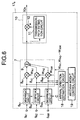
- Fig. 2 is a block diagram showing the adaptive receiver 22 in the conventional array antenna reception apparatus.
- the adaptive receiver 22 is constituted by despread circuits 6 1 to 6 M , weighting synthesizer 7, demodulator 10, complex multiplier 13, subtracter 14, delay circuit 15, and antenna weight control circuit 16.
- the adaptive receiver 22 receives the antenna reception signals S 1 to S M received by the M antenna elements 21 1 to 21 M laid out circularly, and the user determination symbol as an output from the determination circuit 5, and outputs a demodulated signal for a user.
- the despread circuits 6 1 to 6 M calculate correlations between the antenna reception signals S 1 to S M and a user spread code C. Assuming that the spread code C is a complex code made up of two quadrature codes C I and C Q , the despread circuits 6 1 to 6 M can be realized by one complex multiplier and averaging circuits over the symbol section. The despread circuits 6 1 to 6 M can also be realized by a transversal filter arrangement with a tap weight C.
- the weighting synthesizer 7 comprises complex multipliers 8 1 to 8 M and adder 9.
- the weighting synthesizer 7 multiplies outputs from the despread circuits 6 1 to 6 M by antenna weights W r1 to W rM , and adds them to generate a signal received with a directional pattern unique to a desired signal.
- the demodulator 10 comprises a transmission path estimation circuit 11 and complex multiplier 12.
- the product of an output from the weighting synthesizer 7 and the complex conjugate of a transmission path estimation output is the demodulated signal for a user as an output from the adaptive receiver 22.
- the complex multiplier 13 multiplies the user determination symbol by the transmission path estimation output. In multiplying the user determination symbol by the transmission path estimation output, only a component about the phase of the estimation value can be multiplied, and an amplitude obtained by another means can be multiplied. This another means is one for obtaining the amplitude by measuring reception power or the like.
- the subtracter 14 calculates the difference between an output from the complex multiplier 13 and an output from the weighting synthesizer 7, and detects an antenna weight control error e.
- the delay circuit 15 delays outputs from the despread circuits 6 1 to 6 M in accordance with the processing times of the weighting synthesizer 7, demodulator 10, subtracter 14, and the like.
- the antenna weight control circuit 16 calculates the antenna weights W r1 to W rM from the antenna weight control error e and outputs from the delay circuit 15.
- the antenna weight control circuit 16 adaptively controls the antenna weights W r1 to W rM based on the MMSE standard so as to minimize the mean square value of the antenna weight control error e.
- the adaptive control convergence step may use a known symbol instead of the determination symbol.
- the M antenna reception signals S 1 to S M contain desired (user) signal components, interference signal components, and thermal noise.
- Each of the desired signal component and interference signal component contains a multipath component. In general, these signal components arrive from different directions.
- the conventional array antenna reception apparatus shown in Fig. 1 uses an antenna having antenna elements laid out circularly. Thus, a directional pattern with almost uniform reception gains in all the signal arrival directions can be formed.
- the conventional array antenna reception apparatus shown in Fig. 1 cannot attain a high reception gain proportional to the number of antenna elements.
- the conventional array antenna reception apparatus shown in Figs. 1 and 2 decreases in adaptive convergence and stability in forming a directional pattern in the desired user direction.
- the present invention has been made in consideration of the above situation in the prior art, and has as its object to provide an array antenna reception apparatus which can attain a high reception gain proportional to the number of antenna elements and is excellent in adaptive control convergence and stability in forming a directional pattern in the user direction.
- an array antenna reception apparatus is constituted as follows. Antenna elements are linearly laid out on each side (sector) of a polygon, a directional pattern for suppressing interference with another user or multipath is independently formed for each sector, and weighting synthesis is done between sectors.
- the array antenna reception apparatus comprises an array antenna having M (M is an integer of not less than 1) antenna elements linearly laid out on each side (sector) of a polygon having K (K is an integer of not less than 3) sides, K adaptive receivers each for receiving reception signals from the M antenna elements for a corresponding sector, independently forming a directional pattern having a gain in a desired signal direction for the sector, receiving a desired signal, and suppressing an interference signal, and a demodulated signal synthesizer for receiving K demodulated signals as outputs from the K adaptive receivers, weighting and synthesizing the signals, and outputting a demodulated signal for a user.
- M is an integer of not less than 1
- K is an integer of not less than 3
- K adaptive receivers each for receiving reception signals from the M antenna elements for a corresponding sector, independently forming a directional pattern having a gain in a desired signal direction for the sector, receiving a desired signal, and suppressing an interference signal
- a demodulated signal synthesizer
- a directional pattern with a high reception gain substantially proportional to the number of antenna elements can be formed in a direction perpendicular to each straight line (each sector side). Since the directional pattern is independently formed for each sector, the number of antenna elements simultaneously adaptively controlled can be decreased. Even if the number of antenna elements increases, the adaptive convergence and stability are kept high in forming a directional pattern in a desired user direction.
- a multiplexed input signal is a code division multiple signal.
- the first embodiment will exemplify an array antenna reception apparatus (CDMA adaptive reception apparatus) for the number K (K is an integer of 3 or more) of sides (sectors) of a polygon in an antenna and the number M (M is an integer of 1 or more) of antenna elements in each sector.
- CDMA adaptive reception apparatus for the number K (K is an integer of 3 or more) of sides (sectors) of a polygon in an antenna and the number M (M is an integer of 1 or more) of antenna elements in each sector.
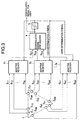
- the array antenna reception apparatus is constituted by an antenna 1 for receiving radio signals to output antenna reception signals (S 11 to S kM ), adaptive receivers 3 1 to 3 K for receiving the antenna reception signals of corresponding sectors to output demodulated sector signals (S D1 to S DK ) of the corresponding sectors, a demodulated signal synthesizer 4, and a determination circuit 5.
- the antenna 1 is made up of antenna elements 2 11 to 2 kM linearly laid out on respective sides (sectors) of a K-side polygon in units of M elements.
- the kth sector will be mainly described.
- the antenna elements 2 k1 to 2 kM in the kth sector are close to each other so as to establish correlations between the antenna reception signals S k1 to S kM in the kth sector, and receive signals obtained by code-multiplexing desired signals and a plurality of interference signals.
- Each of the antenna elements 2 k1 to 2 kM is not particularly limited in horizontal plane directivity, and desirably takes monopole directivity with a beam width of 180° or less. When the antenna elements 2 k1 to 2 kM take monopole directivity with a beam width of 180° or less, they must be arranged to form directivity outside the polygon of the antenna 1.
- a radio shielding member When the antenna elements 2 k1 to 2 kM do not take monopole directivity with a beam width of 180° or less (i.e., omnidirectivity or dipole directivity), a radio shielding member must be disposed inside the K-side polygon of the antenna 1 so as not to receive signals by the antenna elements 2 k1 to 2 kM with directivity inside the kth side (kth sector) of the K-side polygon of the antenna 1.
- M antenna reception signals k1 to kM received by the antenna elements 2 k1 to 2 kM of the kth sector of the antenna 1 are frequency-converted from the radio band to the baseband and A/D-converted.
- the demodulated signal synthesizer 4 receives K demodulated 1st- to kth-sector signals S D1 to S DK as outputs from the adaptive receivers 3 1 to 3 K , weights and synthesizes them, and outputs a demodulated signal for a user.
- the weighting synthesis method in the demodulated signal synthesizer 4 is not particularly limited, and includes a method of selecting only a demodulated signal having the maximum desired signal power, a method of selecting only a demodulated signal having the maximum ratio (SIR) of desired signal power to interference power, and a maximum ratio synthesizing method of maximizing the ratio of desired signal power to interference power.
- the determination circuit 5 receives a demodulated signal for a user as an output from the demodulated signal synthesizer 4 and performs hard determination for the demodulated signal, thereby outputting a user determination symbol.
- a demodulated signal for a user as an output from the demodulated signal synthesizer 4 and performs hard determination for the demodulated signal, thereby outputting a user determination symbol.
- the determination circuit 5 receives a demodulated signal for a user as an output from the demodulated signal synthesizer 4 and performs hard determination for the demodulated signal, thereby outputting a user determination symbol.
- the adaptive receiver 3 K of the kth sector is constituted by despread circuits 6 k1 to 6 kM , weighting synthesizer 7, demodulator 10, complex multiplier 13, subtracter 14, delay circuit 15, and antenna weight control circuit 16.
- the adaptive receiver 3 K of the kth sector receives the antenna reception signals k1 to kM received by the M antenna elements 2 k1 to 2 kM linearly laid out in one sector, and the user determination symbol as an output from the determination circuit 5, and outputs a demodulated kth-sector signal.
- the despread circuits 6 k1 to 6 kM calculate correlations between the antenna signals k1 to kM and a user spread code C. Assuming that the spread code C is a complex code made up of two quadrature codes C I and C Q , the despread circuits 6 k1 to 6 kM can be realized by one complex multiplier and averaging circuits over the symbol section. The despread circuits 6 k1 to 6 kM can also be realized by a transversal filter arrangement with a tap weight C.
- the weighting synthesizer 7 comprises complex multipliers 8 k1 to 8 kM and adder 9.
- the weighting synthesizer 7 multiplies outputs from the despread circuits 6 k1 to 6 kM by antenna weights W rk1 to W rkM , and adds them to generate a signal received with a directional pattern unique to a desired user.
- the demodulator 10 comprises a transmission path estimation circuit 11 and complex multiplier 12.
- the product of an output from the weighting synthesizer 7 and the complex conjugate of a transmission path estimation output is the demodulated kth-sector signal as an output from the adaptive receiver 3 k of the kth sector.
- the complex multiplier 13 multiplies the user determination symbol by the transmission path estimation output.
- multiplying the user determination symbol by the transmission path estimation output only a component about the phase of the estimation value can be multiplied, and an amplitude obtained by another means can be multiplied.
- This another means is one for obtaining the amplitude by measuring, e.g., reception power.
- the subtracter 14 calculates the difference between an output from the complex multiplier 13 and an output from the weighting synthesizer 7, and detects an antenna weight control error e k .
- the delay circuit 15 delays outputs from the despread circuits 6 k1 to 6 kM in accordance with the processing times of the weighting synthesizer 7, demodulator 10, subtracter 14, and the like.
- the antenna weight control circuit 16 calculates the antenna weights W rk1 to W rkM from the antenna weight control error e k and outputs from the delay circuit 15.
- the antenna weight control circuit 16 adaptively controls the antenna weights W rk1 to W rkM based on the MMSE standard so as to minimize the mean square value of the antenna weight control error e k .
- the step size ⁇ as a change amount coefficient in updating the antenna weights W rk1 to W rkM has the following feature.
- the step size ⁇ is large, the convergence speed to the antenna weights W rk1 to W rkM for forming an optimum directional pattern is high, but the adaptive precision and stability are low; when the step size ⁇ is small, the adaptive precision and stability are high, but the convergence speed is low.
- the step size is adaptively changed to obtain a satisfactory convergence speed, adaptive precision, and stability.
- the adaptive control convergence step may use a known symbol instead of the determination symbol.
- the antenna elements 2 k1 to 2 kM are linearly laid out every sector, a directional pattern with a high reception gain substantially proportional to the number of antenna elements can be formed in a direction perpendicular to the linear layout of the antenna elements 2 k1 to 2 kM .
- the directional pattern is independently formed for each sector, the number of antenna elements simultaneously adaptively controlled decreases. Even if the number of antenna elements increases, the adaptive convergence and stability are kept high in forming a directional pattern in a desired user direction.
- a multiplexed input signal is a code division multiple signal.
- the second embodiment will exemplify an array antenna reception apparatus (CDMA adaptive reception apparatus) for the number K (K is an integer of 3 or more) of sides (sectors) of a polygon in an antenna and the number M (M is an integer of 1 or more) of antenna elements in each sector.
- CDMA adaptive reception apparatus CDMA adaptive reception apparatus for the number K (K is an integer of 3 or more) of sides (sectors) of a polygon in an antenna and the number M (M is an integer of 1 or more) of antenna elements in each sector.
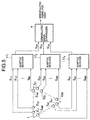
- the array antenna reception apparatus is constituted by an antenna 1, adaptive receivers 17 1 to 17 K , and demodulated signal synthesizer 4.
- the antenna 1 is made up of antenna elements 2 11 to 2 KM linearly laid out on respective sides (sectors) of a K-side polygon in units of M elements.
- the kth sector will be mainly described.
- the antenna elements 2 k1 to 2 kM in the kth sector are close to each other so as to establish correlations between antenna reception signals in the kth sector, and receive signals obtained by code-multiplexing desired signals and a plurality of interference signals.
- Each of the antenna elements 2 k1 to 2 kM is not particularly limited in horizontal plane directivity, and desirably takes monopole directivity with a beam width of 180 degrees or less. When the antenna elements 2 k1 to 2 kM take monopole directivity with a beam width of 180 degrees or less, they must be arranged to form directivity outside the polygon of the antenna 1.
- a radio shielding member must be disposed inside the K-side polygon of the antenna 1 so as not to receive signals by the antenna elements 2 k1 to 2 kM with directivity inside the kth side (kth sector) of the K-side polygon of the antenna 1.
- M antenna reception signals k1 to kM received by the antenna elements 2 k1 to 2 kM of the kth sector of the antenna 1 are frequency-converted from the radio band to the baseband and A/D-converted.
- the demodulated signal synthesizer 4 receives K demodulated 1st- to kth-sector signals as outputs from the adaptive receivers 17 1 to 17 K , weights and synthesizes them, and outputs a demodulated signal for a user.
- the weighting synthesis method in the demodulated signal synthesizer 4 is not particularly limited, and includes a method of selecting only a demodulated signal having the maximum desired signal power, a method of selecting only a demodulated signal having the maximum ratio (SIR) of desired signal power to interference power, and a maximum ratio synthesizing method of maximizing the ratio of desired signal power to interference power.
- the adaptive receiver 17 K of the kth sector is constituted by despread circuits 6 k1 to 6 kM , weighting synthesizer 7, demodulator 10, arrival direction estimation circuit 18, and antenna weight generation circuit 19.
- the adaptive receiver 17 K of the kth sector receives the antenna reception signals k1 to kM received by the M antenna elements 2 k1 to 2 kM linearly laid out in one sector, and outputs a demodulated kth-sector signal.
- the despread circuits 6 k1 to 6 kM calculate correlations between the antenna signals k1 to kM and a user spread code C. Assuming that the spread code C is a complex code made up of two quadrature codes C I and C Q , the despread circuits 6 k1 to 6 kM can be realized by one complex multiplier and averaging circuits over the symbol section. The despread circuits 6 k1 to 6 kM can also be realized by a transversal filter arrangement with a tap weight C.
- the weighting synthesizer 7 comprises complex multipliers 8 k1 to 8 kM and adder 9.
- the weighting synthesizer 7 multiplies outputs from the despread circuits 6 k1 to 6 kM by antenna weights W rk1 to W rkM , and adds them to generate a signal received with a directional pattern unique to a desired user.
- the demodulator 10 comprises a transmission path estimation circuit 11 and complex multiplier 12.
- the product of an output from the weighting synthesizer 7 and the complex conjugate of a transmission path estimation output is the demodulated kth-sector signal as an output from the adaptive receiver 17 k of the kth sector.
- the arrival direction estimation circuit 18 receives outputs from the despread circuits 6 k1 to 6 kM, and estimates the arrival direction of a desired signal from a reception signal multiplexed by a plurality of user signals.
- the arrival direction estimation method in the arrival direction estimation circuit 18 is not limited, and includes, e.g., the MUSIC method.
- the antenna weight generation circuit 19 receives an estimated arrival direction signal as an output from the arrival direction estimation circuit 18, and calculates and outputs the antenna weights W rk1 and W rkM for forming a directional pattern with the maximum reception gain in the estimated arrival direction.
- adaptive control is closed-loop control.
- adaptive control is open loop control and thus can be stably done without any divergence.
- the above embodiments of the present invention do not limit the code length of the spread code C, i.e., the spread ratio.
- the array antenna reception apparatus according to the present invention can be applied to even a signal multiplexed at a spread ratio of 1 by a method other than the code division multiple access method.
- the interval is set to 1/2 the wavelength of the carrier wave.
- the above embodiments of the present invention do not limit the number K of sectors.
- the polygon is a triangle.
Landscapes
- Engineering & Computer Science (AREA)
- Computer Networks & Wireless Communication (AREA)
- Variable-Direction Aerials And Aerial Arrays (AREA)
- Radio Transmission System (AREA)
Applications Claiming Priority (2)
| Application Number | Priority Date | Filing Date | Title |
|---|---|---|---|
| JP10250064A JP2000082982A (ja) | 1998-09-03 | 1998-09-03 | アレーアンテナ受信装置 |
| JP25006498 | 1998-09-03 |
Publications (2)
| Publication Number | Publication Date |
|---|---|
| EP0984507A2 true EP0984507A2 (fr) | 2000-03-08 |
| EP0984507A3 EP0984507A3 (fr) | 2000-12-06 |
Family
ID=17202274
Family Applications (1)
| Application Number | Title | Priority Date | Filing Date |
|---|---|---|---|
| EP99117124A Withdrawn EP0984507A3 (fr) | 1998-09-03 | 1999-08-31 | Dispositif de réception à réseau d'antennes |
Country Status (5)
| Country | Link |
|---|---|
| US (1) | US6792033B1 (fr) |
| EP (1) | EP0984507A3 (fr) |
| JP (1) | JP2000082982A (fr) |
| CN (1) | CN100355220C (fr) |
| CA (1) | CA2281271C (fr) |
Cited By (3)
| Publication number | Priority date | Publication date | Assignee | Title |
|---|---|---|---|---|
| WO2002075957A1 (fr) * | 2001-03-21 | 2002-09-26 | Sanyo Electric Co., Ltd. | Systeme de base sans fil, et procede de commande de directivite |
| US6738016B2 (en) | 2000-03-27 | 2004-05-18 | China Academy Of Telecommunications Technology | Method for improving smart antenna array coverage |
| EP1207583A3 (fr) * | 2000-11-15 | 2006-04-05 | Nec Corporation | Récepteur adaptatif à réseau d'antennes |
Families Citing this family (27)
| Publication number | Priority date | Publication date | Assignee | Title |
|---|---|---|---|---|
| GB2363256B (en) * | 2000-06-07 | 2004-05-12 | Motorola Inc | Adaptive antenna array and method of controlling operation thereof |
| JP4309027B2 (ja) * | 2000-06-27 | 2009-08-05 | マスプロ電工株式会社 | アダプティブアレーアンテナ |
| JP4531969B2 (ja) | 2000-12-21 | 2010-08-25 | 三菱電機株式会社 | アダプティブアンテナ受信装置 |
| FR2822568B1 (fr) * | 2001-03-22 | 2003-06-06 | Mitsubishi Electric Inf Tech | Methode et dispositif d'egalisation de type gmmse |
| DE60107407T2 (de) * | 2001-07-05 | 2005-05-19 | Mitsubishi Electric Information Technology Centre Europe B.V. | Mehrbenutzerdetektion in einem MC-CDMA Telekommunikationssystem |
| EP1300977A1 (fr) * | 2001-10-04 | 2003-04-09 | Mitsubishi Electric Information Technology Centre Europe B.V. | Annulation d'interférence en parallèle dans un système de télécommunication multiporteuse AMCR |
| ATE367682T1 (de) * | 2001-11-21 | 2007-08-15 | Interdigital Tech Corp | Von einer basisstation zum transferieren von daten verwendetes verfahren |
| US6687492B1 (en) * | 2002-03-01 | 2004-02-03 | Cognio, Inc. | System and method for antenna diversity using joint maximal ratio combining |
| EP1769585A4 (fr) | 2002-03-01 | 2009-12-02 | Ipr Licensing Inc | Systeme et procede de combinaison conjointe du rapport maximal par traitement de signaux fonde sur le domaine temporel |
| US6785520B2 (en) | 2002-03-01 | 2004-08-31 | Cognio, Inc. | System and method for antenna diversity using equal power joint maximal ratio combining |
| US6862456B2 (en) | 2002-03-01 | 2005-03-01 | Cognio, Inc. | Systems and methods for improving range for multicast wireless communication |
| US6871049B2 (en) | 2002-03-21 | 2005-03-22 | Cognio, Inc. | Improving the efficiency of power amplifiers in devices using transmit beamforming |
| EP1530255A1 (fr) * | 2003-11-07 | 2005-05-11 | Matsushita Electric Industrial Co., Ltd. | Dispositif d'antenne adaptatif ayant une pluralité de paires d'antennes bidirectionnelles |
| EP1841093B1 (fr) * | 2004-12-27 | 2011-07-27 | Panasonic Corporation | Equipement adaptif d'antenne |
| US7652922B2 (en) | 2005-09-30 | 2010-01-26 | Mosaid Technologies Incorporated | Multiple independent serial link memory |
| KR101260632B1 (ko) * | 2005-09-30 | 2013-05-03 | 모사이드 테크놀로지스 인코퍼레이티드 | 출력 제어 메모리 |
| US20070076502A1 (en) * | 2005-09-30 | 2007-04-05 | Pyeon Hong B | Daisy chain cascading devices |
| US11948629B2 (en) | 2005-09-30 | 2024-04-02 | Mosaid Technologies Incorporated | Non-volatile memory device with concurrent bank operations |
| US7576686B2 (en) * | 2006-08-07 | 2009-08-18 | Garmin International, Inc. | Method and system for calibrating an antenna array for an aircraft surveillance system |
| US7439901B2 (en) * | 2006-08-08 | 2008-10-21 | Garmin International, Inc. | Active phased array antenna for aircraft surveillance systems |
| US20080055150A1 (en) * | 2006-09-06 | 2008-03-06 | Garmin International, Inc. | Method and system for detecting and decoding air traffic control reply signals |
| US7825858B2 (en) * | 2007-02-28 | 2010-11-02 | Garmin International, Inc. | Methods and systems for frequency independent bearing detection |
| US20080284637A1 (en) * | 2007-02-28 | 2008-11-20 | Garmin International, Inc. | Digital tas transmitter and receiver systems and methods |
| US8663074B2 (en) * | 2007-11-07 | 2014-03-04 | Balanced Body, Inc. | Exercise apparatus with a pull cord central pulley attached to a carriage and a pulley locking mechanism |
| KR100911714B1 (ko) | 2007-12-27 | 2009-08-10 | 한국생산기술연구원 | 이동 로봇 위치 추적 방법 |
| JP2009246517A (ja) * | 2008-03-28 | 2009-10-22 | Kyocera Corp | 基地局装置およびチャネル割り当て方法 |
| CN104579511B (zh) * | 2015-01-05 | 2017-05-10 | 电子科技大学 | 一种获得阵列天线接收信号功率误差范围的方法 |
Family Cites Families (24)
| Publication number | Priority date | Publication date | Assignee | Title |
|---|---|---|---|---|
| US4748682A (en) * | 1985-01-08 | 1988-05-31 | Mitsubishi Denki Kabushiki Kaisha | Combined diversity receiving apparatus |
| JP2684888B2 (ja) | 1991-08-06 | 1997-12-03 | 国際電信電話株式会社 | アダプティブアレイアンテナ制御方式 |
| WO1994013031A1 (fr) * | 1992-12-01 | 1994-06-09 | Ntt Mobile Communications Network Inc. | Appareil a antenne multilobe |
| US5410321A (en) * | 1993-09-29 | 1995-04-25 | Texas Instruments Incorporated | Directed reception pattern antenna |
| JP2626514B2 (ja) * | 1993-11-08 | 1997-07-02 | 日本電気株式会社 | 基地局送受信装置 |
| US5757845A (en) * | 1994-02-10 | 1998-05-26 | Ntt Mobile Communications Network | Adaptive spread spectrum receiver |
| JPH07231286A (ja) | 1994-02-18 | 1995-08-29 | Oki Electric Ind Co Ltd | 伝搬路推定器及び移動通信受信装置 |
| US5548813A (en) * | 1994-03-24 | 1996-08-20 | Ericsson Inc. | Phased array cellular base station and associated methods for enhanced power efficiency |
| JP3540374B2 (ja) * | 1994-07-20 | 2004-07-07 | Kddi株式会社 | 移動通信系の基地局用アンテナ装置 |
| US6006069A (en) * | 1994-11-28 | 1999-12-21 | Bosch Telecom Gmbh | Point-to-multipoint communications system |
| US5748683A (en) | 1994-12-29 | 1998-05-05 | Motorola, Inc. | Multi-channel transceiver having an adaptive antenna array and method |
| FI105513B (fi) * | 1995-05-24 | 2000-08-31 | Nokia Networks Oy | Vastaanottomenetelmä sekä vastaanotin |
| JPH08321785A (ja) * | 1995-05-24 | 1996-12-03 | Sony Corp | 送信機,受信機,送信方法,受信方法及び伝送方法 |
| CN1092431C (zh) * | 1995-11-29 | 2002-10-09 | Ntt移动通信网株式会社 | 分集接收机及其控制方法 |
| US5734345A (en) | 1996-04-23 | 1998-03-31 | Trw Inc. | Antenna system for controlling and redirecting communications beams |
| US5657023A (en) | 1996-05-02 | 1997-08-12 | Hughes Electronics | Self-phase up of array antennas with non-uniform element mutual coupling and arbitrary lattice orientation |
| JPH1051215A (ja) | 1996-08-05 | 1998-02-20 | Nippon Telegr & Teleph Corp <Ntt> | アンテナ装置 |
| JP3204111B2 (ja) | 1996-08-28 | 2001-09-04 | 松下電器産業株式会社 | 指向性制御アンテナ装置 |
| JP3287538B2 (ja) | 1996-10-16 | 2002-06-04 | 株式会社エヌ・ティ・ティ・ドコモ | アダプティブ・アレー受信機 |
| JPH10174160A (ja) * | 1996-12-13 | 1998-06-26 | N T T Ido Tsushinmo Kk | アレーアンテナ |
| JPH10173580A (ja) | 1996-12-16 | 1998-06-26 | Fujitsu Ltd | 受信機および受信装置 |
| JP3274388B2 (ja) * | 1997-07-25 | 2002-04-15 | 株式会社東芝 | Rake受信機とこのrake受信機を備えたスぺクトラム拡散通信装置 |
| JP3328930B2 (ja) | 1998-02-13 | 2002-09-30 | 日本電気株式会社 | 適応受信装置 |
| JP3465739B2 (ja) | 1998-04-07 | 2003-11-10 | 日本電気株式会社 | Cdma適応アンテナ受信装置及び通信システム |
-
1998
- 1998-09-03 JP JP10250064A patent/JP2000082982A/ja active Pending
-
1999
- 1999-08-31 EP EP99117124A patent/EP0984507A3/fr not_active Withdrawn
- 1999-09-01 CA CA002281271A patent/CA2281271C/fr not_active Expired - Fee Related
- 1999-09-02 US US09/388,509 patent/US6792033B1/en not_active Expired - Lifetime
- 1999-09-03 CN CNB991195744A patent/CN100355220C/zh not_active Expired - Fee Related
Cited By (5)
| Publication number | Priority date | Publication date | Assignee | Title |
|---|---|---|---|---|
| US6738016B2 (en) | 2000-03-27 | 2004-05-18 | China Academy Of Telecommunications Technology | Method for improving smart antenna array coverage |
| EP1207583A3 (fr) * | 2000-11-15 | 2006-04-05 | Nec Corporation | Récepteur adaptatif à réseau d'antennes |
| US7221698B2 (en) | 2000-11-15 | 2007-05-22 | Nec Corporation | Adaptive array antenna receiving apparatus |
| WO2002075957A1 (fr) * | 2001-03-21 | 2002-09-26 | Sanyo Electric Co., Ltd. | Systeme de base sans fil, et procede de commande de directivite |
| US7403798B2 (en) | 2001-03-21 | 2008-07-22 | Sanyo Electric Co., Ltd. | Wireless base system, and directivity control method |
Also Published As
| Publication number | Publication date |
|---|---|
| CN1249569A (zh) | 2000-04-05 |
| CA2281271C (fr) | 2002-02-12 |
| US6792033B1 (en) | 2004-09-14 |
| JP2000082982A (ja) | 2000-03-21 |
| EP0984507A3 (fr) | 2000-12-06 |
| CA2281271A1 (fr) | 2000-03-03 |
| CN100355220C (zh) | 2007-12-12 |
Similar Documents
| Publication | Publication Date | Title |
|---|---|---|
| US6792033B1 (en) | Array antenna reception apparatus | |
| US7031368B1 (en) | Adaptive transmitter/receiver | |
| JP2914445B2 (ja) | Cdma適応受信装置 | |
| KR100447841B1 (ko) | 웨이트가 적응적으로 갱신되는 적응 안테나 수신 장치 | |
| JP3465739B2 (ja) | Cdma適応アンテナ受信装置及び通信システム | |
| KR100271120B1 (ko) | 다이버시티 수신기 및 그 제어방법 | |
| JP3888189B2 (ja) | 適応アンテナ基地局装置 | |
| US7161976B2 (en) | Interference canceller | |
| US6657590B2 (en) | Adaptive antenna reception apparatus using reception signals by arrays antennas | |
| EP0936755B1 (fr) | Dispositif adaptatif de réception à reseau d'antennes | |
| EP1231720A2 (fr) | Appareil de réception par antennes adaptatif | |
| JP3591581B2 (ja) | 適応アンテナ受信装置 | |
| JP3619729B2 (ja) | 無線受信装置および無線受信方法 | |
| US7565172B2 (en) | Adaptive antenna reception method and device | |
| US7221698B2 (en) | Adaptive array antenna receiving apparatus | |
| JP3328930B2 (ja) | 適応受信装置 | |
| JP4359778B2 (ja) | 初期段階から指向性ビームの受信品質が良好な適応アンテナ受信装置 | |
| EP1146665A1 (fr) | Dispositif de station de base et procede de reception radio | |
| EP1583258B1 (fr) | Dispositif de radiocommunication avec réseau d'antennes | |
| JP2004282472A (ja) | アダプティブアレイアンテナ受信装置 |
Legal Events
| Date | Code | Title | Description |
|---|---|---|---|
| PUAI | Public reference made under article 153(3) epc to a published international application that has entered the european phase |
Free format text: ORIGINAL CODE: 0009012 |
|
| AK | Designated contracting states |
Kind code of ref document: A2 Designated state(s): DE FI FR GB IT SE |
|
| AX | Request for extension of the european patent |
Free format text: AL;LT;LV;MK;RO;SI |
|
| PUAL | Search report despatched |
Free format text: ORIGINAL CODE: 0009013 |
|
| AK | Designated contracting states |
Kind code of ref document: A3 Designated state(s): AT BE CH CY DE DK ES FI FR GB GR IE IT LI LU MC NL PT SE |
|
| AX | Request for extension of the european patent |
Free format text: AL;LT;LV;MK;RO;SI |
|
| RIC1 | Information provided on ipc code assigned before grant |
Free format text: 7H 01Q 3/26 A, 7H 04B 7/08 B |
|
| 17P | Request for examination filed |
Effective date: 20001027 |
|
| AKX | Designation fees paid |
Free format text: DE FI FR GB IT SE |
|
| 17Q | First examination report despatched |
Effective date: 20010316 |
|
| STAA | Information on the status of an ep patent application or granted ep patent |
Free format text: STATUS: THE APPLICATION IS DEEMED TO BE WITHDRAWN |
|
| 18D | Application deemed to be withdrawn |
Effective date: 20060426 |