EP0984523B1 - Connecteur électrique comprenant un capot - Google Patents
Connecteur électrique comprenant un capot Download PDFInfo
- Publication number
- EP0984523B1 EP0984523B1 EP19990117031 EP99117031A EP0984523B1 EP 0984523 B1 EP0984523 B1 EP 0984523B1 EP 19990117031 EP19990117031 EP 19990117031 EP 99117031 A EP99117031 A EP 99117031A EP 0984523 B1 EP0984523 B1 EP 0984523B1
- Authority
- EP
- European Patent Office
- Prior art keywords
- cap
- housing
- parts
- cable
- cavities
- Prior art date
- Legal status (The legal status is an assumption and is not a legal conclusion. Google has not performed a legal analysis and makes no representation as to the accuracy of the status listed.)
- Expired - Lifetime
Links
- 239000000428 dust Substances 0.000 claims description 10
- 239000004020 conductor Substances 0.000 claims description 8
- XLYOFNOQVPJJNP-UHFFFAOYSA-N water Substances O XLYOFNOQVPJJNP-UHFFFAOYSA-N 0.000 claims description 8
- 230000000295 complement effect Effects 0.000 claims description 4
- 230000006870 function Effects 0.000 description 2
- 238000007789 sealing Methods 0.000 description 2
- 230000004308 accommodation Effects 0.000 description 1
- 230000009286 beneficial effect Effects 0.000 description 1
- 238000010276 construction Methods 0.000 description 1
- 230000001419 dependent effect Effects 0.000 description 1
- 238000011161 development Methods 0.000 description 1
- 230000018109 developmental process Effects 0.000 description 1
- 238000004519 manufacturing process Methods 0.000 description 1
- 230000009993 protective function Effects 0.000 description 1
Images




Classifications
-
- H—ELECTRICITY
- H01—ELECTRIC ELEMENTS
- H01R—ELECTRICALLY-CONDUCTIVE CONNECTIONS; STRUCTURAL ASSOCIATIONS OF A PLURALITY OF MUTUALLY-INSULATED ELECTRICAL CONNECTING ELEMENTS; COUPLING DEVICES; CURRENT COLLECTORS
- H01R13/00—Details of coupling devices of the kinds covered by groups H01R12/70 or H01R24/00 - H01R33/00
- H01R13/46—Bases; Cases
- H01R13/516—Means for holding or embracing insulating body, e.g. casing, hoods
-
- H—ELECTRICITY
- H01—ELECTRIC ELEMENTS
- H01R—ELECTRICALLY-CONDUCTIVE CONNECTIONS; STRUCTURAL ASSOCIATIONS OF A PLURALITY OF MUTUALLY-INSULATED ELECTRICAL CONNECTING ELEMENTS; COUPLING DEVICES; CURRENT COLLECTORS
- H01R13/00—Details of coupling devices of the kinds covered by groups H01R12/70 or H01R24/00 - H01R33/00
- H01R13/46—Bases; Cases
- H01R13/52—Dustproof, splashproof, drip-proof, waterproof, or flameproof cases
- H01R13/5205—Sealing means between cable and housing, e.g. grommet
Definitions
- the invention relates to an electrical connector with a housing containing contacts attached to the electrical conductors of a cable, and in particular to a cap which can be mounted to a cable end of the housing to surround the cable tightly in order to protect the cavity from the ingress of dust and water.
- a connector having a housing with contact cavities for electrical contacts attached to electrical conductors of a cable, and a cap that can be mounted on the housing at a cable end of the housing.
- the cap includes an integrated contact securing device for securing the contacts in the cavities and consists of two parts which can be joined together perpendicular to the plugging direction.
- the objective of this invention is to provide a connector with a protection from the ingress of dust and water as well as a structure for securing the contacts therein, that is surely mounted when the cap is mounted.
- the objective is achieved by an arrangement with the features of claim 1, whereby the special design of the cap ensures that when the cap is mounted to the housing the integrated contact securing device is also brought into its final position.
- This is achieved by joining the two parts of the cap to the housing by a positive guiding arrangement which operates in the plugging direction when moving the contact securing device into its final position.
- This positively guided arrangement is achieved by sliding slots incorporated in the cap parts and sliding blocks in the housing.
- a cap in addition to the housing only one other part is required, a cap, in order to both secure the contacts in their cavities and to protect the housing against the ingress of dust and water.
- the cap comprises two parts interconnected in a flexible manner, which ensures that the two parts can be handled as one part and not as separate entities.
- the cap is provided with a mechanical strain-relief for the cable.
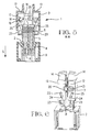
- the claimed electrical connector includes a connector housing 1 which, in turn, consists of two parts: a housing 2 and a cap 3.
- the housing 2 comprises two parallel rows of four contact cavities 4.
- the contact cavities 4 accommodate electrical contacts 5, indicated schematically in figures 4 and 5.
- the cap 3 is pushed onto the housing 2 from cable end 7.
- the cap 3 comprises two parts 12 and 13.
- the two parts 12, 13 are split shells provided with a semi-circular cable end 14.
- the two semi-circular parts 14 form a circular end which will tightly surround a cable (not shown).
- a sealing lip 15 is formed within the semi-circular end 14, to provide a seal around the cable, thus affording protection from dust and water.
- the cable end 14 with its dust protection lip 15 can function as a mechanical strain-relief.
- the two parts 12 and 13 are not fully independent from each other but linked by plastic bands 16.
- the plastic bands 16 are flexible, thereby allowing the parts to be moved in relation to each other.
- a contact securing device 17 is included within each of the split shell parts 12, 13, a contact securing device 17 is included.
- the contact securing device 17 takes the form of a comb-shaped rib configured to embrace a number of conductors of the cable when the cap 3 is joined together.
- the contact securing device 17 is provided with semi-circular apertures 18 to accommodate respective electrical conductors.
- the contact securing device 17 is provided with a rib 19 that engages in a cavity 4 when the cap is shifted in a longitudinal direction away from the cable end.
- each part 12, 13 is provided with a corresponding latching arrangement 20, 21.
- On facing sides of one part 12 of the cap 3 is provided with at least one latching lug 21 whereas the other part 13 on the corresponding facing side is provided with a latching arm 20 having a latch opening 22.
- Latching arms with latching openings are also provided at the housing end of the cap 3. These latching elements 23 interact with the corresponding latching lugs 11 at the housing 3.
- the housing 2 is provided with a pair of sliding blocks 24 at opposite sides near the cable end 7.
- a corresponding sliding slot 25 is located on facing sides.
- Figures 1, 4 and 9 show clearly that adjacent to the sealing lip 15 the circular end 14 is provided with a further semi-circular rib 26.
- This rib can, for example, be employed as strain-relief.
Landscapes
- Connector Housings Or Holding Contact Members (AREA)
Claims (5)
- Connecteur électrique comprenant un boítier (2) comportant des cavités de contact (4) pour des contacts électriques fixés sur des conducteurs électriques d'un câble, et un capuchon (3) pouvant être monté sur le boítier au niveau d'une extrémité du câble du boítier, le capuchon (3) englobant un dispositif de fixation des contacts solidaire (17) destiné à fixer les contacts (5) dans les cavités (4) et composé de deux parties (12, 13) pouvant être assemblées perpendiculairement à la direction d'enfichage, caractérisé en ce que le capuchon (3) est fixé fermement autour du câble pour protéger le boítier (2) contre la pénétration de poussières et d'eau, en ce que le capuchon (3) est guidé de manière positive sur le boítier (2), de sorte que lors de l'assemblage des parties (12, 13) perpendiculairement à la direction d'enfichage (S), le capuchon est déplacé dans la direction d'enfichage, déplaçant ainsi le dispositif de fixation des contacts (17) dans sa position d'extrémité, et en ce que les parties (12, 13) du capuchon (3) comportent des fentes coulissantes (25), le boítier (2) comportant des blocs coulissants (24) destinés à être guidés dans les fentes coulissantes (25) lorsque le capuchon (3) est monté sur le boítier (2), assurant ainsi le déplacement dans la direction d'enfichage.
- Connecteur électrique selon la revendication 1, caractérisé en ce que le dispositif de fixation des contacts (17) comporte des nervures individuelles (19) s'engageant à partir de l'extrémité du câble dans les cavités (4) pour fixer les contacts (5).
- Connecteur selon la revendication 1, caractérisé en ce que le capuchon (3) comporte des éléments de verrouillage (23), le boítier (2) comportant des éléments de verrouillage complémentaires (11), fixant fermement le capuchon (3) sur le boítier (2) dans une position d'extrémité.
- Connecteur selon la revendication 1, caractérisé en ce que les parties (12, 13) comportent des agencements de verrouillage complémentaires (20, 21) en vue de leur assemblage par verrouillage.
- Connecteur selon la revendication 1, caractérisé en ce que les parties (12, 13) sont assemblées de manière flexible, les deux parties pouvant ainsi être manipulées comme une seule pièce et non pas comme des pièces séparées.
Priority Applications (1)
| Application Number | Priority Date | Filing Date | Title |
|---|---|---|---|
| EP19990117031 EP0984523B1 (fr) | 1998-08-31 | 1999-08-30 | Connecteur électrique comprenant un capot |
Applications Claiming Priority (3)
| Application Number | Priority Date | Filing Date | Title |
|---|---|---|---|
| EP98116419 | 1998-08-31 | ||
| EP98116419 | 1998-08-31 | ||
| EP19990117031 EP0984523B1 (fr) | 1998-08-31 | 1999-08-30 | Connecteur électrique comprenant un capot |
Publications (2)
| Publication Number | Publication Date |
|---|---|
| EP0984523A1 EP0984523A1 (fr) | 2000-03-08 |
| EP0984523B1 true EP0984523B1 (fr) | 2003-01-22 |
Family
ID=26149591
Family Applications (1)
| Application Number | Title | Priority Date | Filing Date |
|---|---|---|---|
| EP19990117031 Expired - Lifetime EP0984523B1 (fr) | 1998-08-31 | 1999-08-30 | Connecteur électrique comprenant un capot |
Country Status (1)
| Country | Link |
|---|---|
| EP (1) | EP0984523B1 (fr) |
Families Citing this family (2)
| Publication number | Priority date | Publication date | Assignee | Title |
|---|---|---|---|---|
| DE102005030554A1 (de) * | 2005-06-22 | 2006-12-28 | Lapp Engineering & Co. | Steckverbinderelement |
| US8790129B1 (en) * | 2013-01-14 | 2014-07-29 | Deutsch Engineered Connecting Devices, Inc. | User configurable connector |
Family Cites Families (3)
| Publication number | Priority date | Publication date | Assignee | Title |
|---|---|---|---|---|
| US4372634A (en) * | 1981-03-04 | 1983-02-08 | Amp Incorporated | Tilt latch zero insertion force connector assembly |
| JP2582750Y2 (ja) * | 1992-10-06 | 1998-10-08 | 住友電装株式会社 | コネクタ用カバー |
| US5762520A (en) * | 1996-04-30 | 1998-06-09 | The Whitaker Corporation | Hermaphroditic wire cover |
-
1999
- 1999-08-30 EP EP19990117031 patent/EP0984523B1/fr not_active Expired - Lifetime
Also Published As
| Publication number | Publication date |
|---|---|
| EP0984523A1 (fr) | 2000-03-08 |
Similar Documents
| Publication | Publication Date | Title |
|---|---|---|
| EP0955697B1 (fr) | Connecteur étanche | |
| US6302734B1 (en) | Waterproof connector with sealing member | |
| EP0072104B1 (fr) | Connecteur électrique scellé | |
| US6817888B2 (en) | Connector with cover | |
| EP0306635B1 (fr) | Connecteur électrique | |
| US5762520A (en) | Hermaphroditic wire cover | |
| US6059594A (en) | Sealed electrical connector | |
| EP0948101B1 (fr) | Connecteur électrique pour mise en contact avec au moins un conducteur à feuille plate | |
| EP3648259B1 (fr) | Connecteur électrique avec verrous et projections d'assurance de position de terminal fourni sur un couvercle articulé | |
| US4588242A (en) | Sealed electrical connector | |
| WO2008071917A1 (fr) | Connecteur d'extrémité de câbles de communication | |
| CN107210565A (zh) | 屏蔽连接器 | |
| CN102427183B (zh) | 线盖、电线的布线方法以及电连接器 | |
| CN101473494A (zh) | 密封电连接器 | |
| US20190148873A1 (en) | Electrical device having a seal assembly | |
| EP0001885B1 (fr) | Assemblage de connecteurs électriques avec des moyens de blocage | |
| AU2007349106B2 (en) | Electric connector with a dust cover | |
| US6132250A (en) | Connector with sealing members | |
| JP2704316B2 (ja) | 電気コネクタハウジング組立体 | |
| US4257666A (en) | Plug | |
| KR20100027009A (ko) | 밀봉된 전기 커넥터 | |
| EP0984523A1 (fr) | Connecteur électrique comprenant un capot | |
| CN102576960A (zh) | 电线盖的安装结构 | |
| EP1037322B1 (fr) | Dispositif resistant à l'eau pour un connecteur | |
| EP0581320A1 (fr) | Connecteur électrique |
Legal Events
| Date | Code | Title | Description |
|---|---|---|---|
| PUAI | Public reference made under article 153(3) epc to a published international application that has entered the european phase |
Free format text: ORIGINAL CODE: 0009012 |
|
| AK | Designated contracting states |
Kind code of ref document: A1 Designated state(s): DE FR GB |
|
| AX | Request for extension of the european patent |
Free format text: AL;LT;LV;MK;RO;SI |
|
| 17P | Request for examination filed |
Effective date: 20000914 |
|
| AKX | Designation fees paid |
Free format text: DE FR GB |
|
| 17Q | First examination report despatched |
Effective date: 20010226 |
|
| GRAG | Despatch of communication of intention to grant |
Free format text: ORIGINAL CODE: EPIDOS AGRA |
|
| GRAG | Despatch of communication of intention to grant |
Free format text: ORIGINAL CODE: EPIDOS AGRA |
|
| GRAH | Despatch of communication of intention to grant a patent |
Free format text: ORIGINAL CODE: EPIDOS IGRA |
|
| GRAH | Despatch of communication of intention to grant a patent |
Free format text: ORIGINAL CODE: EPIDOS IGRA |
|
| GRAA | (expected) grant |
Free format text: ORIGINAL CODE: 0009210 |
|
| AK | Designated contracting states |
Kind code of ref document: B1 Designated state(s): DE FR GB |
|
| PG25 | Lapsed in a contracting state [announced via postgrant information from national office to epo] |
Ref country code: FR Free format text: LAPSE BECAUSE OF FAILURE TO SUBMIT A TRANSLATION OF THE DESCRIPTION OR TO PAY THE FEE WITHIN THE PRESCRIBED TIME-LIMIT Effective date: 20030122 |
|
| REG | Reference to a national code |
Ref country code: GB Ref legal event code: FG4D |
|
| REF | Corresponds to: |
Ref document number: 69904997 Country of ref document: DE Date of ref document: 20030227 Kind code of ref document: P |
|
| PLBE | No opposition filed within time limit |
Free format text: ORIGINAL CODE: 0009261 |
|
| STAA | Information on the status of an ep patent application or granted ep patent |
Free format text: STATUS: NO OPPOSITION FILED WITHIN TIME LIMIT |
|
| EN | Fr: translation not filed | ||
| 26N | No opposition filed |
Effective date: 20031023 |
|
| PGFP | Annual fee paid to national office [announced via postgrant information from national office to epo] |
Ref country code: GB Payment date: 20170829 Year of fee payment: 19 |
|
| PGFP | Annual fee paid to national office [announced via postgrant information from national office to epo] |
Ref country code: DE Payment date: 20180814 Year of fee payment: 20 |
|
| GBPC | Gb: european patent ceased through non-payment of renewal fee |
Effective date: 20180830 |
|
| REG | Reference to a national code |
Ref country code: DE Ref legal event code: R071 Ref document number: 69904997 Country of ref document: DE |
|
| PG25 | Lapsed in a contracting state [announced via postgrant information from national office to epo] |
Ref country code: GB Free format text: LAPSE BECAUSE OF NON-PAYMENT OF DUE FEES Effective date: 20180830 |