EP0984532A1 - Article comprenant un résonateur Raman à fibre en cascade - Google Patents
Article comprenant un résonateur Raman à fibre en cascade Download PDFInfo
- Publication number
- EP0984532A1 EP0984532A1 EP99306126A EP99306126A EP0984532A1 EP 0984532 A1 EP0984532 A1 EP 0984532A1 EP 99306126 A EP99306126 A EP 99306126A EP 99306126 A EP99306126 A EP 99306126A EP 0984532 A1 EP0984532 A1 EP 0984532A1
- Authority
- EP
- European Patent Office
- Prior art keywords
- refractive index
- wavelength
- gratings
- grating
- reflectivity
- Prior art date
- Legal status (The legal status is an assumption and is not a legal conclusion. Google has not performed a legal analysis and makes no representation as to the accuracy of the status listed.)
- Granted
Links
- 238000001069 Raman spectroscopy Methods 0.000 title claims abstract description 41
- 239000013307 optical fiber Substances 0.000 title claims abstract description 16
- 230000005855 radiation Effects 0.000 claims abstract description 39
- 238000002310 reflectometry Methods 0.000 claims abstract description 38
- 238000011144 upstream manufacturing Methods 0.000 claims description 20
- VYPSYNLAJGMNEJ-UHFFFAOYSA-N Silicium dioxide Chemical compound O=[Si]=O VYPSYNLAJGMNEJ-UHFFFAOYSA-N 0.000 claims description 16
- 239000000377 silicon dioxide Substances 0.000 claims description 8
- 230000003287 optical effect Effects 0.000 abstract 1
- 239000000835 fiber Substances 0.000 description 21
- 238000001228 spectrum Methods 0.000 description 7
- 238000005253 cladding Methods 0.000 description 3
- 230000003321 amplification Effects 0.000 description 2
- 238000006243 chemical reaction Methods 0.000 description 2
- 230000007423 decrease Effects 0.000 description 2
- 238000003199 nucleic acid amplification method Methods 0.000 description 2
- 230000003595 spectral effect Effects 0.000 description 2
- 229910052691 Erbium Inorganic materials 0.000 description 1
- 239000000853 adhesive Substances 0.000 description 1
- 230000001070 adhesive effect Effects 0.000 description 1
- 230000005540 biological transmission Effects 0.000 description 1
- 239000004020 conductor Substances 0.000 description 1
- 230000003247 decreasing effect Effects 0.000 description 1
- 230000009977 dual effect Effects 0.000 description 1
- UYAHIZSMUZPPFV-UHFFFAOYSA-N erbium Chemical compound [Er] UYAHIZSMUZPPFV-UHFFFAOYSA-N 0.000 description 1
- 238000010438 heat treatment Methods 0.000 description 1
- 230000003993 interaction Effects 0.000 description 1
- 238000004519 manufacturing process Methods 0.000 description 1
- 238000005457 optimization Methods 0.000 description 1
- 230000001902 propagating effect Effects 0.000 description 1
- 238000005086 pumping Methods 0.000 description 1
Images


Classifications
-
- H—ELECTRICITY
- H01—ELECTRIC ELEMENTS
- H01S—DEVICES USING THE PROCESS OF LIGHT AMPLIFICATION BY STIMULATED EMISSION OF RADIATION [LASER] TO AMPLIFY OR GENERATE LIGHT; DEVICES USING STIMULATED EMISSION OF ELECTROMAGNETIC RADIATION IN WAVE RANGES OTHER THAN OPTICAL
- H01S3/00—Lasers, i.e. devices using stimulated emission of electromagnetic radiation in the infrared, visible or ultraviolet wave range
- H01S3/30—Lasers, i.e. devices using stimulated emission of electromagnetic radiation in the infrared, visible or ultraviolet wave range using scattering effects, e.g. stimulated Brillouin or Raman effects
- H01S3/302—Lasers, i.e. devices using stimulated emission of electromagnetic radiation in the infrared, visible or ultraviolet wave range using scattering effects, e.g. stimulated Brillouin or Raman effects in an optical fibre
-
- H—ELECTRICITY
- H01—ELECTRIC ELEMENTS
- H01S—DEVICES USING THE PROCESS OF LIGHT AMPLIFICATION BY STIMULATED EMISSION OF RADIATION [LASER] TO AMPLIFY OR GENERATE LIGHT; DEVICES USING STIMULATED EMISSION OF ELECTROMAGNETIC RADIATION IN WAVE RANGES OTHER THAN OPTICAL
- H01S3/00—Lasers, i.e. devices using stimulated emission of electromagnetic radiation in the infrared, visible or ultraviolet wave range
- H01S3/05—Construction or shape of optical resonators; Accommodation of active medium therein; Shape of active medium
- H01S3/06—Construction or shape of active medium
- H01S3/063—Waveguide lasers, i.e. whereby the dimensions of the waveguide are of the order of the light wavelength
- H01S3/067—Fibre lasers
- H01S3/0675—Resonators including a grating structure, e.g. distributed Bragg reflectors [DBR] or distributed feedback [DFB] fibre lasers
-
- H—ELECTRICITY
- H01—ELECTRIC ELEMENTS
- H01S—DEVICES USING THE PROCESS OF LIGHT AMPLIFICATION BY STIMULATED EMISSION OF RADIATION [LASER] TO AMPLIFY OR GENERATE LIGHT; DEVICES USING STIMULATED EMISSION OF ELECTROMAGNETIC RADIATION IN WAVE RANGES OTHER THAN OPTICAL
- H01S3/00—Lasers, i.e. devices using stimulated emission of electromagnetic radiation in the infrared, visible or ultraviolet wave range
- H01S3/05—Construction or shape of optical resonators; Accommodation of active medium therein; Shape of active medium
- H01S3/08—Construction or shape of optical resonators or components thereof
- H01S3/08086—Multiple-wavelength emission
-
- H—ELECTRICITY
- H01—ELECTRIC ELEMENTS
- H01S—DEVICES USING THE PROCESS OF LIGHT AMPLIFICATION BY STIMULATED EMISSION OF RADIATION [LASER] TO AMPLIFY OR GENERATE LIGHT; DEVICES USING STIMULATED EMISSION OF ELECTROMAGNETIC RADIATION IN WAVE RANGES OTHER THAN OPTICAL
- H01S3/00—Lasers, i.e. devices using stimulated emission of electromagnetic radiation in the infrared, visible or ultraviolet wave range
- H01S3/09—Processes or apparatus for excitation, e.g. pumping
- H01S3/091—Processes or apparatus for excitation, e.g. pumping using optical pumping
- H01S3/094—Processes or apparatus for excitation, e.g. pumping using optical pumping by coherent light
- H01S3/094042—Processes or apparatus for excitation, e.g. pumping using optical pumping by coherent light of a fibre laser
- H01S3/094046—Processes or apparatus for excitation, e.g. pumping using optical pumping by coherent light of a fibre laser of a Raman fibre laser
Definitions
- This invention pertains to optical fiber cascaded Raman resonators (CRR) and to articles that comprise the CRR (e.g., a Raman laser, or an optical fiber communication system that includes a Raman laser).
- CRR optical fiber cascaded Raman resonators
- Optical fiber Raman lasers are known. See, for instance, U. S. Patent No. 5,323,404.
- a cascaded Raman resonator receives pump radiation of wavelength ⁇ p (typically from a laser diode array and a cladding pumped fiber laser), and shifts radiation power in one or more steps to a desired output wavelength ⁇ s > ⁇ p .
- the step size typically is about 13.2 THz, corresponding to the maximum in the Raman gain spectrum of silica.
- the step size is determined by reflectors (typically refractive index gratings) in the optical fiber.
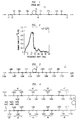
- FIG. 1 schematically depicts an exemplary prior art CRR 10.
- the pump source can be conventional (e.g., comprising a diode laser array and a cladding pumped fiber laser) and is not shown.
- pump light of wavelength ⁇ p propagates from fiber 11 to fiber 12 through fibers 13, 14 and 15, all single mode silica-based fibers.
- Fiber 15 typically is of order 1 km in length, and advantageously has low effective area to maximize Raman gain.
- Numerals 161, 162-16n are conventional high reflectivity (e.g., >90%) refractive index gratings.
- Downstream gratings 171, 172 ... 17n are matched in center wavelength to upstream gratings 161 ...
- gratings 171-17n are a low reflectivity grating, with all others having high reflectivity.
- the pump wavelength ⁇ p is 1117 nm
- the output wavelength ⁇ s is 1480 nm
- the intermediate Stokes-Raman orders are 1175, 1240, 1310 and 1395 nm, corresponding to the center wavelengths of the respective grating pairs.
- the prior art CRR of FIG. 1 comprises an optional high reflectivity pump reflector grating 18 (with center wavelength ⁇ p ), as well as a low reflectivity (e.g., about 5%) output grating of center wavelength ⁇ s .
- the grating pair 161/171 corresponds to the first intermediate Stokes-Bragg order
- the pair 16n/17n corresponds to the output wavelength.
- the light of an intermediate Raman-Stokes order circulates in its resonator until the light is substantially entirely converted into the next Raman-Stokes order.
- FIG. 3 of the '404 patent shows an exemplary spectrum of a prior art CRR.
- the pump radiation of wavelength ⁇ p is derived from a high power pump that typically comprises a commercially available diode laser array and a cladding pumped fiber laser that serves to convert the multimode radiation from the diode laser array into single mode radiation of the appropriate wavelength.
- CRRs as described above are finding a variety of uses, e.g., providing 1480 nm pump radiation for EDFAs, or providing pump radiation for Raman amplification of signal wavelengths of about 1.55 ⁇ m from 1100 nm pump light.
- the invention is embodied in a multi-wavelength CRR adapted for receiving pump radiation of wavelength ⁇ p , and for providing output radiation of at least two different wavelengths ⁇ s,1 and ⁇ s,2 .
- a significant aspect of the invention is the recognition that the frequency shift between adjacent Raman orders need not be limited to about 13.2 THz, as is prior art practice, but can be selected to be substantially any desired value in the approximate range 0-40 THz, being mindful of decreased conversion efficiency for frequency shifts that differ substantially from the peak frequency shift of about 13.2 THz.
- the invention is embodied in an article that comprises a CRR comprising a length of silica-based single mode optical fiber.
- the optical fiber comprises a first multiplicity of upstream refractive index gratings and a second multiplicity of downstream refractive index gratings, with single mode optical fiber disposed between said upstream and downstream refractive index gratings.
- Each refractive index grating has a center wavelength and a reflectivity at the center wavelength .
- the CRR is adapted for receiving pump radiation of wavelength ⁇ p at a location upstream of said upstream refractive index gratings, and is furthermore adapted for providing, at a location downstream of the downstream refractive index gratings, output radiation of wavelength ⁇ s,1 > ⁇ p .
- the CRR is a multi-wavelength CRR that is adapted for providing, at the location downstream of the downstream refractive index gratings, at least one further output radiation of wavelength ⁇ s,2 > ⁇ p
- said first multiplicity of upstream refractive index gratings comprises a first and second refractive index grating
- said second multiplicity of downstream refractive index gratings comprises a third and fourth refractive index grating.
- the first and third refractive index gratings are selected to have center wavelengths ⁇ s,1
- the second and fourth refractive index gratings are selected to have center wavelength ⁇ s,2 .
- the first and third refractive index gratings are selected such that the first refractive index grating has a reflectivity at the center wavelength ⁇ s,1 that is larger than the reflectivity at the center wavelength ⁇ s,1 of the third refractive index grating, and the second and fourth refractive index gratings are selected such that the second refractive index grating has a reflectivity at the center wavelength ⁇ s,2 that is larger than the reflectivity at the center wavelength ⁇ s,2 of the fourth refractive index grating.
- the reflectivities at the respective center wavelengths of the first and second refractive index gratings are greater than 50%, and the reflectivities at the respective center wavelengths of the third and fourth refractive index gratings are less than 50%.
- Embodiments of the invention are not limited to two output wavelengths but can have three or even more different output wavelengths, limited substantially only by power considerations.
- the refractive index gratings can be conventional, with the "high reflectivity" first and second gratings desirably and typically having 80% or more reflectivity, and the "low reflectivity" third and fourth gratings typically having 20% or less reflectivity.
- the single mode fiber between the two sets of refractive index gratings typically has relatively small core size, to facilitate Raman shifting, and typically has a length of order 1 km, e.g., in the range 0.3-3 km.
- a CRR according to the invention also has one or more pairs of essentially identical gratings, with one member of a given pair in the upstream set, and the other number of the given pair in the downstream set. These pairs form resonator cavities that cause Raman shifting of the radiation.
- the set of downstream gratings comprises a high reflectivity grating of center wavelength ⁇ p , to serve as pump reflector.
- the pump reflector typically is, but need not be, the last grating in the downstream direction of the CRR.
- Preferred embodiments of the invention comprise means for controlling the output power at the respective wavelengths.
- Such control can be provided by means of an adjustable coupler at the output, or by tuning or de-tuning of a grating pair.
- CRRs according to the invention can be provided with an appropriate pump radiation source to yield a Raman resonator radiation source (frequently referred to as a Raman laser).
- a Raman resonator radiation source (frequently referred to as a Raman laser).
- a radiation source can be used in a variety of ways, e.g., to provide pump radiation for an EDFA or for a distributed Raman amplifier, all in optical fiber communication systems, or for a combination of a zero loss dispersion-compensating fiber and EDFA for a combination of remote pumping and amplification of the signal. See also EP-A-0903 877.
- the Raman gain spectrum of silica exhibits gain over a spectral region extending about 40 THz, with a broad peak at about 13.2 THz.
- high power pump light can produce Raman gain substantially anywhere in this 40 THz range, providing flexibility in the design of a CRR.
- existence of this relatively broad gain band makes possible design of multi-wavelength CRRs, including CRRs with relatively widely spaced output wavelengths.
- a frequency shift of -13 THz corresponds to a wavelength shift of about 53 nm
- a frequency shift of -13 THz corresponds to a wavelength shift of about 72 nm.
- the downstream set of refractive index gratings includes, for each output wavelength, a "low reflectivity” grating having center wavelength essentially equal to a desired output wavelength
- the upstream set of refractive index gratings includes, for each output wavelength, a "high reflectivity” grating having center wavelength essentially equal to the desired output wavelength.
- a center wavelength is “essentially” equal to another center wavelength if the center wavelengths differ at most due to unavoidable manufacturing variations.
- FIG. 3 schematically shows an exemplary CRR 30 according to the invention.
- all four digit numbers are in nanometers, and splices are not shown.
- the upstream gratings as well as the downstream gratings are formed in conventional manner in silica-based single mode optical fiber.
- Raman-active fiber 15 is 0.5 km of silica-based single mode optical fiber substantially like the corresponding fiber of the '404 patent.
- ⁇ p is 1100 nm
- ⁇ s,1 and ⁇ s,2 are 1457 and 1486 nm, respectively.
- Pump radiation ⁇ p is coupled into the upstream end of the CRR, propagates therethrough, and the unconverted pump radiation is reflected by 1100 nm pump reflector at the downstream end of the CRR.
- the grating pairs with center wavelengths 1155, 1217, 1286 and 1363 nm all are high reflectivity gratings (reflectivity at the center wavelength ⁇ 90%).
- the upstream 1457 and 1486 nm gratings are also high reflectivity gratings, but the corresponding downstream gratings are low reflectivity gratings (reflectivity at center wavelength respectively about 20% and about 63%), frequently referred to as "output couplers". Due to the presence of the two high reflectivity reflectors and the two output couplers at 1457 and 1486 nm, the CRR of FIG. 3 can provide output variation at 1457 and 1486 nm wavelength.
- the placement of the output couplers is not critical, provided they are disposed downstream of Raman fiber 15.
- the 1457 nm output coupler could be placed just downstream or upstream of the 1486 nm coupler.
- FIG. 4 schematically shows a further exemplary embodiment of the invention, adapted for producing six different wavelengths from pump radiation of wavelength 1121 nm.
- All upstream gratings (designated by numerals 41, 43, 45 and 47) are high reflectivity gratings, and the downstream gratings comprise high reflectivity gratings (designated 44 and 48) as well as six output couplers, namely the gratings designated 42 and 46.
- Grating 49 is a pump reflector.
- Pump radiation is also Raman shifted to 1155 nm, then 1217 nm, 1286 nm and 1363 nm. The latter then is Raman shifted to 1447, 1450 and 1453.
- Output couplers 42 and 46 facilitate emission of radiation of wavelengths 1422, 1425, 1428 nm, and of wavelengths 1447, 1450 and 1453 nm.
- An important aspect of CRRs in general, and of multi-wavelength CRRs according to the invention in particular, is the selection of the center wavelengths of the gratings.
- the goal of the selection is efficient shifting of the light from the pump wavelength ⁇ p to the desired output wavelengths.
- the gratings advantageously are selected such that, for each given set of resonators, the wavelength differences between adjacent gratings are approximately equal.
- the gratings are selected such that the corresponding frequency is, exemplarily, in the approximate range 7-25 THz.
- the gratings are shown disposed in a particular order, e.g., with increasing center wavelengths in the downstream direction. This was done for the sake of clarity but is not a necessary feature. Indeed, the order in which the members of a set of gratings are disposed in the fiber in general is not critical.
- FIGs. 5 and 6 show the relevant portions of the output spectrum of a CRR substantially as shown in FIG. 3.
- the spectra clearly show significant light intensity at about 1486 and 1457 nm, respectively. Optimization of the CRR is expected to result in even greater intensity at the desired output wavelengths.
- the power can also be controlled by tuning or de-tuning one or more resonance cavities.
- tuning or de-tuning is readily accomplished by application of stress to one grating of a pair of gratings, and/or by changing the temperature of a grating of a pair, resulting in a shift of the center wavelength of the grating.
- the efficiency of a CRR increases with improved tuning of the resonance cavities, and decreases with de-tuning of the cavities.
- changing the center wavelength of a grating such that said center wavelength is not exactly equal to the center wavelength of the other grating of a pair decreases the cavity quality factor (Q), as compared to the Q of the resonance cavity with exactly matched pair.
- FIG. 7 schematically shows an exemplary tunable grating for use in a CRR according to the invention.
- Optical fiber 71 comprising refractive index grating 72, is attached by adhesive or other appropriate means 75 to piezoelectric member 73.
- Appropriately placed electrodes 74 and conductors 76 facilitate application of a voltage across the member, such that the length of the member (and consequently the repeat distance A of the grating) is a function of the applied voltage.
- A can also be changed by changing the temperature of the fiber region that contains the grating. This is accomplished for instance by enclosing the grating in a housing with a heating element therein.
- FIG. 8 schematically depicts a remotely pumped communication system 80 that comprises a dual-wavelength CRR according to the invention.
- Transmitter 81 is signal-transmissively connected to receiver 82 by means of optical fiber 83.
- conventional EDFA erbium doped fiber amplifier
- Dual wavelength Raman laser 85 is in the vicinity of the receiver, and is pumped by conventional pump source 86.
- Pump radiation 861 exemplarily has wavelength 1100 nm.
- the Raman laser is substantially as shown in FIG. 3, with output radiation of about 1450 nm and 1480 nm, and includes a coupler (not shown) for separating the two wavelengths.
- the 1450 nm radiation 851 is coupled into transmission fiber 83 in the vicinity of the receiver by means of conventional coupler 842.
- the radiation propagates in fiber 83 in the upstream direction and serves to provide distributed gain for signal radiation propagating from the transmitter to the receiver.
- the 1480 nm radiation 852 propagates through fiber 87 to the vicinity of EDFA 84, and is coupled into fiber 83 just downstream of the EDFA.
- the 1480 nm radiation serves as pump radiation for the EDFA, which provides gain for the signal radiation that propagates from transmitter to receiver.
- FIG. 8 conventional features such as isolators, splices, etc., are not shown.
Landscapes
- Physics & Mathematics (AREA)
- Electromagnetism (AREA)
- Engineering & Computer Science (AREA)
- Plasma & Fusion (AREA)
- Optics & Photonics (AREA)
- Optical Modulation, Optical Deflection, Nonlinear Optics, Optical Demodulation, Optical Logic Elements (AREA)
- Lasers (AREA)
- Optical Fibers, Optical Fiber Cores, And Optical Fiber Bundles (AREA)
- Optical Communication System (AREA)
Applications Claiming Priority (2)
| Application Number | Priority Date | Filing Date | Title |
|---|---|---|---|
| US134296 | 1980-03-26 | ||
| US09/134,296 US6163552A (en) | 1998-08-14 | 1998-08-14 | Article comprising an optical fiber cascaded Raman resonator |
Publications (2)
| Publication Number | Publication Date |
|---|---|
| EP0984532A1 true EP0984532A1 (fr) | 2000-03-08 |
| EP0984532B1 EP0984532B1 (fr) | 2001-10-17 |
Family
ID=22462711
Family Applications (1)
| Application Number | Title | Priority Date | Filing Date |
|---|---|---|---|
| EP99306126A Expired - Lifetime EP0984532B1 (fr) | 1998-08-14 | 1999-08-02 | Article comprenant un résonateur Raman à fibre en cascade |
Country Status (4)
| Country | Link |
|---|---|
| US (1) | US6163552A (fr) |
| EP (1) | EP0984532B1 (fr) |
| JP (1) | JP2000075150A (fr) |
| DE (1) | DE69900360T2 (fr) |
Cited By (8)
| Publication number | Priority date | Publication date | Assignee | Title |
|---|---|---|---|---|
| WO2001099243A1 (fr) * | 2000-06-20 | 2001-12-27 | Evotec Oai Ag | Laser a fibre optique |
| WO2001033285A3 (fr) * | 1999-10-29 | 2002-01-24 | Sdl Inc | Sources optiques a longueurs d'ondes multiples |
| WO2002043198A3 (fr) * | 2000-11-06 | 2002-09-12 | Cidra Corp | Laser et amplificateur raman accordables |
| GB2380313A (en) * | 2001-09-28 | 2003-04-02 | Marconi Caswell Ltd | Raman Device |
| EP1329995A1 (fr) * | 2002-01-11 | 2003-07-23 | Alcatel | Laser à fibre Raman à résonateur en cascade, et système optique comportant un tel laser |
| EP1349242A1 (fr) * | 2002-03-27 | 2003-10-01 | Alcatel | Amplificateur Raman à fibre; Système optique et méthode de contrôle de l'amplificateur Raman à fibre |
| EP1217764A3 (fr) * | 2000-12-22 | 2004-03-31 | Alcatel | Amplificateur Raman à large bande |
| EP1241749A3 (fr) * | 2001-03-16 | 2004-11-10 | Siemens Aktiengesellschaft | Source de pompage optique à puissance élevé pour amplification du type Raman à bande large |
Families Citing this family (29)
| Publication number | Priority date | Publication date | Assignee | Title |
|---|---|---|---|---|
| US6327289B1 (en) * | 1997-09-02 | 2001-12-04 | Matsushita Electric Industrial Co., Ltd. | Wavelength-variable semiconductor laser, optical integrated device utilizing the same, and production method thereof |
| US6434172B1 (en) * | 1999-08-06 | 2002-08-13 | Fitel Usa Corp. | Article comprising a fiber raman device |
| US6862380B2 (en) * | 2000-02-04 | 2005-03-01 | At&T Corp. | Transparent optical switch |
| RU2158458C1 (ru) * | 2000-02-08 | 2000-10-27 | Научный центр волоконной оптики при Институте общей физики РАН | Рамановский волоконный лазер |
| US6466363B1 (en) * | 2000-09-27 | 2002-10-15 | Nortel Networks Limited | Broadband amplification with first and second amplifiers having different pump wavelength requirements |
| US6959021B2 (en) | 2001-02-07 | 2005-10-25 | Ocg Technology Licensing, Llc | Raman fiber laser |
| US6807338B2 (en) * | 2001-03-12 | 2004-10-19 | Fitel Usa Corp. | Multiwavelength cascaded raman resonator |
| WO2002093704A1 (fr) | 2001-05-15 | 2002-11-21 | Ocg Technology Licensing, Llc | Fibre optique et systemes contenant cette fibre optique |
| AU2002316478A1 (en) * | 2001-07-02 | 2003-01-21 | Ogg Technology Licensing, Llc. | Multi-wavelength optical fiber |
| US6525870B1 (en) | 2001-07-26 | 2003-02-25 | Ciena Corporation | Method and system for controlling Raman gain flatness sensitivity to pump laser wavelength variation |
| JP4612243B2 (ja) * | 2001-07-30 | 2011-01-12 | 関西電力株式会社 | ラマン光増幅器 |
| WO2003014771A2 (fr) * | 2001-08-03 | 2003-02-20 | Ocg Technology Licensing, Llc | Amplificateur de fibre optique |
| WO2003044914A1 (fr) * | 2001-11-16 | 2003-05-30 | Optical Power Systems Inc. | Laser a fibre raman a longueurs d'onde multiples |
| US6721088B2 (en) * | 2002-03-15 | 2004-04-13 | Ofs Fitel | Single-source multiple-order raman amplifier for optical transmission systems |
| ATE363755T1 (de) * | 2002-07-24 | 2007-06-15 | Alcatel Lucent | Kaskadierter ramanlaser |
| US7391561B2 (en) | 2005-07-29 | 2008-06-24 | Aculight Corporation | Fiber- or rod-based optical source featuring a large-core, rare-earth-doped photonic-crystal device for generation of high-power pulsed radiation and method |
| US7768700B1 (en) | 2006-11-30 | 2010-08-03 | Lockheed Martin Corporation | Method and apparatus for optical gain fiber having segments of differing core sizes |
| US7916386B2 (en) * | 2007-01-26 | 2011-03-29 | Ofs Fitel, Llc | High power optical apparatus employing large-mode-area, multimode, gain-producing optical fibers |
| EP2109788B1 (fr) * | 2007-02-05 | 2018-10-31 | Furukawa Electric North America Inc. | Dopage segmenté de gain d'une fibre optique |
| US8179594B1 (en) | 2007-06-29 | 2012-05-15 | Lockheed Martin Corporation | Method and apparatus for spectral-beam combining of fanned-in laser beams with chromatic-dispersion compensation using a plurality of diffractive gratings |
| JP5323562B2 (ja) * | 2008-03-31 | 2013-10-23 | 古河電気工業株式会社 | カスケードラマンレーザ |
| US8503840B2 (en) | 2010-08-23 | 2013-08-06 | Lockheed Martin Corporation | Optical-fiber array method and apparatus |
| US8441718B2 (en) | 2009-11-23 | 2013-05-14 | Lockheed Martin Corporation | Spectrally beam combined laser system and method at eye-safer wavelengths |
| WO2011130131A1 (fr) | 2010-04-12 | 2011-10-20 | Lockheed Martin Corporation | Système de diagnostic et de rétroaction à faisceaux et procédé pour des lasers à faisceaux combinés spectralement |
| JP5878165B2 (ja) * | 2010-04-21 | 2016-03-08 | モビアス フォトニクス, インク. | 多波長ラマンレーザ |
| US8976446B2 (en) | 2012-06-19 | 2015-03-10 | Bae Systems Information And Electronic Systems Integration Inc. | Efficient extended shift monolithic raman fiber laser |
| US9366872B2 (en) | 2014-02-18 | 2016-06-14 | Lockheed Martin Corporation | Apparatus and method for fiber-laser output-beam shaping for spectral beam combination |
| US9318876B1 (en) * | 2015-01-22 | 2016-04-19 | Trumpf Photonics, Inc. | Arrangement of multiple diode laser module and method for operating the same |
| WO2020107030A1 (fr) * | 2018-11-23 | 2020-05-28 | Nuburu, Inc | Source laser visible à longueurs d'onde multiples |
Citations (4)
| Publication number | Priority date | Publication date | Assignee | Title |
|---|---|---|---|---|
| US4063106A (en) * | 1977-04-25 | 1977-12-13 | Bell Telephone Laboratories, Incorporated | Optical fiber Raman oscillator |
| US5268910A (en) * | 1991-07-18 | 1993-12-07 | General Instrument Corporation | Superluminescent optical source |
| US5323404A (en) * | 1993-11-02 | 1994-06-21 | At&T Bell Laboratories | Optical fiber laser or amplifier including high reflectivity gratings |
| US5450427A (en) * | 1994-10-21 | 1995-09-12 | Imra America, Inc. | Technique for the generation of optical pulses in modelocked lasers by dispersive control of the oscillation pulse width |
Family Cites Families (3)
| Publication number | Priority date | Publication date | Assignee | Title |
|---|---|---|---|---|
| US5623508A (en) * | 1996-02-12 | 1997-04-22 | Lucent Technologies Inc. | Article comprising a counter-pumped optical fiber raman amplifier |
| US5815518A (en) * | 1997-06-06 | 1998-09-29 | Lucent Technologies Inc. | Article comprising a cascaded raman fiber laser |
| US5966480A (en) * | 1998-02-23 | 1999-10-12 | Lucent Technologies Inc. | Article comprising an improved cascaded optical fiber Raman device |
-
1998
- 1998-08-14 US US09/134,296 patent/US6163552A/en not_active Expired - Lifetime
-
1999
- 1999-08-02 EP EP99306126A patent/EP0984532B1/fr not_active Expired - Lifetime
- 1999-08-02 DE DE69900360T patent/DE69900360T2/de not_active Expired - Lifetime
- 1999-08-13 JP JP11228978A patent/JP2000075150A/ja active Pending
Patent Citations (4)
| Publication number | Priority date | Publication date | Assignee | Title |
|---|---|---|---|---|
| US4063106A (en) * | 1977-04-25 | 1977-12-13 | Bell Telephone Laboratories, Incorporated | Optical fiber Raman oscillator |
| US5268910A (en) * | 1991-07-18 | 1993-12-07 | General Instrument Corporation | Superluminescent optical source |
| US5323404A (en) * | 1993-11-02 | 1994-06-21 | At&T Bell Laboratories | Optical fiber laser or amplifier including high reflectivity gratings |
| US5450427A (en) * | 1994-10-21 | 1995-09-12 | Imra America, Inc. | Technique for the generation of optical pulses in modelocked lasers by dispersive control of the oscillation pulse width |
Cited By (14)
| Publication number | Priority date | Publication date | Assignee | Title |
|---|---|---|---|---|
| US6549329B2 (en) | 1999-10-29 | 2003-04-15 | Jds Uniphase Corporation | Multiple wavelength optical sources |
| WO2001033285A3 (fr) * | 1999-10-29 | 2002-01-24 | Sdl Inc | Sources optiques a longueurs d'ondes multiples |
| US6407855B1 (en) | 1999-10-29 | 2002-06-18 | Sdl, Inc. | Multiple wavelength optical sources |
| US7027467B2 (en) | 2000-06-20 | 2006-04-11 | Evotec Technologies Gmbh | Fiber laser |
| WO2001099243A1 (fr) * | 2000-06-20 | 2001-12-27 | Evotec Oai Ag | Laser a fibre optique |
| US6594288B1 (en) | 2000-11-06 | 2003-07-15 | Cidra Corporation | Tunable raman laser and amplifier |
| WO2002043198A3 (fr) * | 2000-11-06 | 2002-09-12 | Cidra Corp | Laser et amplificateur raman accordables |
| EP1217764A3 (fr) * | 2000-12-22 | 2004-03-31 | Alcatel | Amplificateur Raman à large bande |
| US7154662B2 (en) | 2000-12-22 | 2006-12-26 | Alcatel | Broadband Raman amplifier |
| EP1241749A3 (fr) * | 2001-03-16 | 2004-11-10 | Siemens Aktiengesellschaft | Source de pompage optique à puissance élevé pour amplification du type Raman à bande large |
| GB2380313A (en) * | 2001-09-28 | 2003-04-02 | Marconi Caswell Ltd | Raman Device |
| EP1329995A1 (fr) * | 2002-01-11 | 2003-07-23 | Alcatel | Laser à fibre Raman à résonateur en cascade, et système optique comportant un tel laser |
| US6836488B2 (en) | 2002-01-11 | 2004-12-28 | Alcatel | Cascaded Raman fiber laser, and optical system including such a laser |
| EP1349242A1 (fr) * | 2002-03-27 | 2003-10-01 | Alcatel | Amplificateur Raman à fibre; Système optique et méthode de contrôle de l'amplificateur Raman à fibre |
Also Published As
| Publication number | Publication date |
|---|---|
| JP2000075150A (ja) | 2000-03-14 |
| DE69900360D1 (de) | 2001-11-22 |
| US6163552A (en) | 2000-12-19 |
| DE69900360T2 (de) | 2002-07-11 |
| EP0984532B1 (fr) | 2001-10-17 |
Similar Documents
| Publication | Publication Date | Title |
|---|---|---|
| EP0984532B1 (fr) | Article comprenant un résonateur Raman à fibre en cascade | |
| US6625180B2 (en) | Raman fiber laser | |
| JP3357291B2 (ja) | ラマンファイバレーザを有するシステム | |
| CA2387645C (fr) | Sources optiques a longueurs d'ondes multiples | |
| EP0938172B1 (fr) | Appareil comprenant un laser Raman à fibre en cascade amélioré | |
| EP0651479B1 (fr) | Appareil comprenant un laser ou un amplificateur à fibre optique | |
| US6310899B1 (en) | Cascaded raman resonator system and apparatus | |
| US6434172B1 (en) | Article comprising a fiber raman device | |
| US20020118709A1 (en) | Broadband sagnac raman amplifiers and cascade lasers | |
| US8224139B2 (en) | Tunable optical filter | |
| EP1160941A1 (fr) | Laser et amplificateur optique à guide d'onde à stabilité thermique améliorée | |
| JP4063908B2 (ja) | 光源装置、光増幅器及び光通信システム | |
| US6768750B2 (en) | Multi-spectral line Raman laser | |
| EP1318579A1 (fr) | Laser raman à longueurs d'ondes multiples | |
| US7463411B2 (en) | Optical fiber amplifier | |
| US20040179797A1 (en) | Multi-wavelength optical fiber | |
| US6836488B2 (en) | Cascaded Raman fiber laser, and optical system including such a laser | |
| Su et al. | Design of wavelength-switching erbium-doped fiber lasers with a multimode fiber Bragg grating using spatial-mode excitation and selection techniques | |
| US20030184848A1 (en) | Raman fiber amplification stage, optical system and method to control the Raman amplification | |
| Février et al. | 12 nm FWHM 20 dB stop-band filter based on cascaded dual concentric core fibre filters | |
| GB2380313A (en) | Raman Device | |
| Im et al. | An all-fibre robust and tunable Raman fibre laser with reconfigurable asymmetric cavities | |
| CA2396751A1 (fr) | Resonateur raman en cascade a structure de reseau echantillonne | |
| Hann et al. | Multiple wavelength Raman fibre laser with asymmetric cavities | |
| EP1331708A1 (fr) | Laser, amplificateur optique, et méthode pour obtenir de la lumière laser et amplifier des signaux optiques |
Legal Events
| Date | Code | Title | Description |
|---|---|---|---|
| PUAI | Public reference made under article 153(3) epc to a published international application that has entered the european phase |
Free format text: ORIGINAL CODE: 0009012 |
|
| 17P | Request for examination filed |
Effective date: 19990812 |
|
| AK | Designated contracting states |
Kind code of ref document: A1 Designated state(s): DE FR GB IT |
|
| AX | Request for extension of the european patent |
Free format text: AL;LT;LV;MK;RO;SI |
|
| AKX | Designation fees paid |
Free format text: DE FR GB IT |
|
| GRAG | Despatch of communication of intention to grant |
Free format text: ORIGINAL CODE: EPIDOS AGRA |
|
| RTI1 | Title (correction) |
Free format text: ARTICLE COMPRISING AN OPTICAL FIBER CASCADED RAMAN RESONATOR |
|
| 17Q | First examination report despatched |
Effective date: 20001218 |
|
| GRAG | Despatch of communication of intention to grant |
Free format text: ORIGINAL CODE: EPIDOS AGRA |
|
| GRAH | Despatch of communication of intention to grant a patent |
Free format text: ORIGINAL CODE: EPIDOS IGRA |
|
| GRAH | Despatch of communication of intention to grant a patent |
Free format text: ORIGINAL CODE: EPIDOS IGRA |
|
| GRAA | (expected) grant |
Free format text: ORIGINAL CODE: 0009210 |
|
| AK | Designated contracting states |
Kind code of ref document: B1 Designated state(s): DE FR GB IT |
|
| REF | Corresponds to: |
Ref document number: 69900360 Country of ref document: DE Date of ref document: 20011122 |
|
| REG | Reference to a national code |
Ref country code: GB Ref legal event code: IF02 |
|
| ET | Fr: translation filed | ||
| PLBE | No opposition filed within time limit |
Free format text: ORIGINAL CODE: 0009261 |
|
| STAA | Information on the status of an ep patent application or granted ep patent |
Free format text: STATUS: NO OPPOSITION FILED WITHIN TIME LIMIT |
|
| 26N | No opposition filed | ||
| REG | Reference to a national code |
Ref country code: GB Ref legal event code: 732E Free format text: REGISTERED BETWEEN 20131121 AND 20131127 |
|
| REG | Reference to a national code |
Ref country code: FR Ref legal event code: CD Owner name: ALCATEL-LUCENT USA INC. Effective date: 20131122 |
|
| REG | Reference to a national code |
Ref country code: FR Ref legal event code: GC Effective date: 20140410 |
|
| REG | Reference to a national code |
Ref country code: FR Ref legal event code: RG Effective date: 20141015 |
|
| REG | Reference to a national code |
Ref country code: FR Ref legal event code: PLFP Year of fee payment: 17 |
|
| REG | Reference to a national code |
Ref country code: FR Ref legal event code: PLFP Year of fee payment: 18 |
|
| PGFP | Annual fee paid to national office [announced via postgrant information from national office to epo] |
Ref country code: GB Payment date: 20160819 Year of fee payment: 18 Ref country code: DE Payment date: 20160822 Year of fee payment: 18 Ref country code: IT Payment date: 20160825 Year of fee payment: 18 |
|
| PGFP | Annual fee paid to national office [announced via postgrant information from national office to epo] |
Ref country code: FR Payment date: 20160822 Year of fee payment: 18 |
|
| REG | Reference to a national code |
Ref country code: DE Ref legal event code: R119 Ref document number: 69900360 Country of ref document: DE |
|
| GBPC | Gb: european patent ceased through non-payment of renewal fee |
Effective date: 20170802 |
|
| REG | Reference to a national code |
Ref country code: FR Ref legal event code: ST Effective date: 20180430 |
|
| PG25 | Lapsed in a contracting state [announced via postgrant information from national office to epo] |
Ref country code: DE Free format text: LAPSE BECAUSE OF NON-PAYMENT OF DUE FEES Effective date: 20180301 Ref country code: GB Free format text: LAPSE BECAUSE OF NON-PAYMENT OF DUE FEES Effective date: 20170802 |
|
| PG25 | Lapsed in a contracting state [announced via postgrant information from national office to epo] |
Ref country code: IT Free format text: LAPSE BECAUSE OF NON-PAYMENT OF DUE FEES Effective date: 20170802 Ref country code: FR Free format text: LAPSE BECAUSE OF NON-PAYMENT OF DUE FEES Effective date: 20170831 |
|
| REG | Reference to a national code |
Ref country code: DE Ref legal event code: R081 Ref document number: 69900360 Country of ref document: DE Owner name: WSOU INVESTMENTS, LLC, LOS ANGELES, US Free format text: FORMER OWNER: LUCENT TECHNOLOGIES INC., MURRAY HILL, N.J., US |