EP0984587A2 - Anschlusseinrichtung für die Gebäudesystemtechnik - Google Patents
Anschlusseinrichtung für die Gebäudesystemtechnik Download PDFInfo
- Publication number
- EP0984587A2 EP0984587A2 EP99113833A EP99113833A EP0984587A2 EP 0984587 A2 EP0984587 A2 EP 0984587A2 EP 99113833 A EP99113833 A EP 99113833A EP 99113833 A EP99113833 A EP 99113833A EP 0984587 A2 EP0984587 A2 EP 0984587A2
- Authority
- EP
- European Patent Office
- Prior art keywords
- connection device
- coupling module
- bus
- coupling
- interface
- Prior art date
- Legal status (The legal status is an assumption and is not a legal conclusion. Google has not performed a legal analysis and makes no representation as to the accuracy of the status listed.)
- Granted
Links
Images



Classifications
-
- H—ELECTRICITY
- H02—GENERATION; CONVERSION OR DISTRIBUTION OF ELECTRIC POWER
- H02J—ELECTRIC POWER NETWORKS; CIRCUIT ARRANGEMENTS OR SYSTEMS FOR SUPPLYING OR DISTRIBUTING ELECTRIC POWER; SYSTEMS FOR STORING ELECTRIC ENERGY
- H02J13/00—Circuit arrangements for providing remote monitoring or remote control of equipment in a power distribution network
- H02J13/13—Circuit arrangements for providing remote monitoring or remote control of equipment in a power distribution network characterised by the transmission of data to equipment in the power network
- H02J13/1331—Circuit arrangements for providing remote monitoring or remote control of equipment in a power distribution network characterised by the transmission of data to equipment in the power network using wireless data transmission
-
- H—ELECTRICITY
- H02—GENERATION; CONVERSION OR DISTRIBUTION OF ELECTRIC POWER
- H02J—ELECTRIC POWER NETWORKS; CIRCUIT ARRANGEMENTS OR SYSTEMS FOR SUPPLYING OR DISTRIBUTING ELECTRIC POWER; SYSTEMS FOR STORING ELECTRIC ENERGY
- H02J13/00—Circuit arrangements for providing remote monitoring or remote control of equipment in a power distribution network
- H02J13/13—Circuit arrangements for providing remote monitoring or remote control of equipment in a power distribution network characterised by the transmission of data to equipment in the power network
- H02J13/1311—Circuit arrangements for providing remote monitoring or remote control of equipment in a power distribution network characterised by the transmission of data to equipment in the power network using the power network as support for the transmission
-
- H—ELECTRICITY
- H02—GENERATION; CONVERSION OR DISTRIBUTION OF ELECTRIC POWER
- H02J—ELECTRIC POWER NETWORKS; CIRCUIT ARRANGEMENTS OR SYSTEMS FOR SUPPLYING OR DISTRIBUTING ELECTRIC POWER; SYSTEMS FOR STORING ELECTRIC ENERGY
- H02J13/00—Circuit arrangements for providing remote monitoring or remote control of equipment in a power distribution network
- H02J13/13—Circuit arrangements for providing remote monitoring or remote control of equipment in a power distribution network characterised by the transmission of data to equipment in the power network
- H02J13/1321—Circuit arrangements for providing remote monitoring or remote control of equipment in a power distribution network characterised by the transmission of data to equipment in the power network using a wired telecommunication network or a data transmission bus
-
- H—ELECTRICITY
- H02—GENERATION; CONVERSION OR DISTRIBUTION OF ELECTRIC POWER
- H02J—ELECTRIC POWER NETWORKS; CIRCUIT ARRANGEMENTS OR SYSTEMS FOR SUPPLYING OR DISTRIBUTING ELECTRIC POWER; SYSTEMS FOR STORING ELECTRIC ENERGY
- H02J13/00—Circuit arrangements for providing remote monitoring or remote control of equipment in a power distribution network
- H02J13/18—Circuit arrangements for providing remote monitoring or remote control of equipment in a power distribution network characterised by the remotely-controlled equipment, e.g. converters or transformers
- H02J13/34—Circuit arrangements for providing remote monitoring or remote control of equipment in a power distribution network characterised by the remotely-controlled equipment, e.g. converters or transformers the equipment being switches, relays or circuit breakers
-
- Y—GENERAL TAGGING OF NEW TECHNOLOGICAL DEVELOPMENTS; GENERAL TAGGING OF CROSS-SECTIONAL TECHNOLOGIES SPANNING OVER SEVERAL SECTIONS OF THE IPC; TECHNICAL SUBJECTS COVERED BY FORMER USPC CROSS-REFERENCE ART COLLECTIONS [XRACs] AND DIGESTS
- Y02—TECHNOLOGIES OR APPLICATIONS FOR MITIGATION OR ADAPTATION AGAINST CLIMATE CHANGE
- Y02B—CLIMATE CHANGE MITIGATION TECHNOLOGIES RELATED TO BUILDINGS, e.g. HOUSING, HOUSE APPLIANCES OR RELATED END-USER APPLICATIONS
- Y02B90/00—Enabling technologies or technologies with a potential or indirect contribution to GHG emissions mitigation
- Y02B90/20—Smart grids as enabling technology in buildings sector
-
- Y—GENERAL TAGGING OF NEW TECHNOLOGICAL DEVELOPMENTS; GENERAL TAGGING OF CROSS-SECTIONAL TECHNOLOGIES SPANNING OVER SEVERAL SECTIONS OF THE IPC; TECHNICAL SUBJECTS COVERED BY FORMER USPC CROSS-REFERENCE ART COLLECTIONS [XRACs] AND DIGESTS
- Y04—INFORMATION OR COMMUNICATION TECHNOLOGIES HAVING AN IMPACT ON OTHER TECHNOLOGY AREAS
- Y04S—SYSTEMS INTEGRATING TECHNOLOGIES RELATED TO POWER NETWORK OPERATION, COMMUNICATION OR INFORMATION TECHNOLOGIES FOR IMPROVING THE ELECTRICAL POWER GENERATION, TRANSMISSION, DISTRIBUTION, MANAGEMENT OR USAGE, i.e. SMART GRIDS
- Y04S40/00—Systems for electrical power generation, transmission, distribution or end-user application management characterised by the use of communication or information technologies, or communication or information technology specific aspects supporting them
- Y04S40/12—Systems for electrical power generation, transmission, distribution or end-user application management characterised by the use of communication or information technologies, or communication or information technology specific aspects supporting them characterised by data transport means between the monitoring, controlling or managing units and monitored, controlled or operated electrical equipment
- Y04S40/121—Systems for electrical power generation, transmission, distribution or end-user application management characterised by the use of communication or information technologies, or communication or information technology specific aspects supporting them characterised by data transport means between the monitoring, controlling or managing units and monitored, controlled or operated electrical equipment using the power network as support for the transmission
-
- Y—GENERAL TAGGING OF NEW TECHNOLOGICAL DEVELOPMENTS; GENERAL TAGGING OF CROSS-SECTIONAL TECHNOLOGIES SPANNING OVER SEVERAL SECTIONS OF THE IPC; TECHNICAL SUBJECTS COVERED BY FORMER USPC CROSS-REFERENCE ART COLLECTIONS [XRACs] AND DIGESTS
- Y04—INFORMATION OR COMMUNICATION TECHNOLOGIES HAVING AN IMPACT ON OTHER TECHNOLOGY AREAS
- Y04S—SYSTEMS INTEGRATING TECHNOLOGIES RELATED TO POWER NETWORK OPERATION, COMMUNICATION OR INFORMATION TECHNOLOGIES FOR IMPROVING THE ELECTRICAL POWER GENERATION, TRANSMISSION, DISTRIBUTION, MANAGEMENT OR USAGE, i.e. SMART GRIDS
- Y04S40/00—Systems for electrical power generation, transmission, distribution or end-user application management characterised by the use of communication or information technologies, or communication or information technology specific aspects supporting them
- Y04S40/12—Systems for electrical power generation, transmission, distribution or end-user application management characterised by the use of communication or information technologies, or communication or information technology specific aspects supporting them characterised by data transport means between the monitoring, controlling or managing units and monitored, controlled or operated electrical equipment
- Y04S40/124—Systems for electrical power generation, transmission, distribution or end-user application management characterised by the use of communication or information technologies, or communication or information technology specific aspects supporting them characterised by data transport means between the monitoring, controlling or managing units and monitored, controlled or operated electrical equipment using wired telecommunication networks or data transmission busses
-
- Y—GENERAL TAGGING OF NEW TECHNOLOGICAL DEVELOPMENTS; GENERAL TAGGING OF CROSS-SECTIONAL TECHNOLOGIES SPANNING OVER SEVERAL SECTIONS OF THE IPC; TECHNICAL SUBJECTS COVERED BY FORMER USPC CROSS-REFERENCE ART COLLECTIONS [XRACs] AND DIGESTS
- Y04—INFORMATION OR COMMUNICATION TECHNOLOGIES HAVING AN IMPACT ON OTHER TECHNOLOGY AREAS
- Y04S—SYSTEMS INTEGRATING TECHNOLOGIES RELATED TO POWER NETWORK OPERATION, COMMUNICATION OR INFORMATION TECHNOLOGIES FOR IMPROVING THE ELECTRICAL POWER GENERATION, TRANSMISSION, DISTRIBUTION, MANAGEMENT OR USAGE, i.e. SMART GRIDS
- Y04S40/00—Systems for electrical power generation, transmission, distribution or end-user application management characterised by the use of communication or information technologies, or communication or information technology specific aspects supporting them
- Y04S40/12—Systems for electrical power generation, transmission, distribution or end-user application management characterised by the use of communication or information technologies, or communication or information technology specific aspects supporting them characterised by data transport means between the monitoring, controlling or managing units and monitored, controlled or operated electrical equipment
- Y04S40/126—Systems for electrical power generation, transmission, distribution or end-user application management characterised by the use of communication or information technologies, or communication or information technology specific aspects supporting them characterised by data transport means between the monitoring, controlling or managing units and monitored, controlled or operated electrical equipment using wireless data transmission
Definitions
- the invention relates to a connection device for the Building system technology for connecting devices to an information bus.
- EP-PS 0 344 609 B1 describes a digital signal transmission system for home automation systems, for which data telegrams between various connection devices installed in the building can be transferred. The data transfer takes place for the purpose of switching, controlling, regulating, measuring and / or monitoring, the connection units performing the function of input and / or output units.
- To the connection units can external electrical devices, detectors or Function sensors can be connected. Enable the connection units the communication of external devices with the house control system.
- Connection units are required for standardization of the system to be installed in the building, that each connection device from a universal interface, and a device adapter (input / output part).
- the universal interfaces are hardware-related among themselves constructed the same way so that when installing the system initially only one universal interface on each connection side, which contains a microprocessor to be installed.
- the universal interface is combined with the function-specific Device adapter connected, which completes the connection device and you convey the behavior that for the Communication with a specific external device type required is.
- EP 0 365 696 B1 is a transmission system for coupling of transmitting and receiving stations on a two-wire bus known that works with direct current. The information will superimposed as an alternating voltage, with the coupling of several Stations on the bus and for coupling or coupling in Messages, each provided a coupling device which has a coupling circuit.
- Bus systems that use an optical transmission path for example an infrared transmission link, have another other coupling circuit.
- connection devices of a bus system only for coupling to a specific transmission medium, such as a two-wire line, or Power-Net, or light or radio.
- connection devices for this are required to keep different bus media (means of transmission) in stock and manage, thereby increasing technical and logistical effort is required.
- the object of the invention is a connection device for building system engineering to create simple Way on different transmission media from Information buses can be customized.
- connection facilities for example a two-wire line or a power supply line or a radio transmission, but with different types of transmission are used, for example Narrowband or broadband transmission, or full duplex or Half duplex transmission, frequency or amplitude modulation; but also different telegram structures, like them for example with the EIB bus or the BATI bus.
- a uniform Use transmission medium for information transmission for example a two-wire line or a power supply line or a radio transmission, but with different types of transmission are used, for example Narrowband or broadband transmission, or full duplex or Half duplex transmission, frequency or amplitude modulation; but also different telegram structures, like them for example with the EIB bus or the BATI bus.
- the invention is based on the consideration that essential assemblies the connection device like that Input / output device, the device for generating Telegrams, the device for converting an analog value into a digital value and vice versa and facilities for Allocation of source and destination addresses or group addresses can be standardized regardless of the transmission medium, and thus only different coupling modules to adapt to Transmission medium of the information bus are required their coupling circuits adapted to the transmission medium are and contain a transmitting and receiving device.
- a bus medium-independent is standardized Interface available that contain a microprocessor can.
- This interface can be supplemented by the separate Coupling modules, each matched to a transmission medium are and contained in a connection device Interface to convey that behavior about different Transmission media with one or more connection devices to communicate. Then it will only be for different transmission media of the information bus, such as Two-wire lines, power supply lines, light, ultrasound or radio, give appropriate coupling modules, their Coupling circuits on the respective transmission medium are coordinated.
- the connection device can be a flush-mounted version, Surface-mounted version or built-in version be, the functional part of the universal interface may be identical for all designs, but at least same configurations for inserting the coupling modules have.
- the transmission medium a two-wire line, so there is a coupling module, that as an interface between the connection device and the Two-wire bus line works.
- the transmission medium one Power supply line, so there is another coupling module, that instead of the two-wire coupling module with the connection device is usable.
- the transmission medium for example a radio link, or an optical link, so there is also a radio coupling module or an optical coupling module.
- Each coupling module has an electrically detectable identifier, recognized by the standardizable functional part becomes.
- the identifier can consist, for example, that with With the help of an identification line that standardized Functional part with the coupling module via the coupling module interface connects and in the coupling module to a bus medium-specific DC potential is set, and that standardized functional part contains an analog / digital converter, the potential of the identification line in one Converts digital value.
- the microprocessor is programmed for various bus media and recognizes the respective coupling module and adjusts the data traffic to the bus medium.
- every coupling module contains a bus medium-specific "physical layer” which essentially as a signal coupling and signal coupling device can be represented.
- Each coupling module with its “Physical layer” then interacts with the "link layer", which again interacts with the "network layer” or the “transport layer” etc.
- the "link layer” contains Functions dependent on the bus medium that interact with the "Physical layers” of the coupling modules are available and the adaptation to different bus media.
- a practical application example can be such look like an information bus partly on a two-wire basis and operated partly on radio or infrared basis becomes.
- they are standardized Functional parts of the corresponding two-wire coupling modules and in the second case the corresponding infrared coupling modules or radio coupling modules to use.
- the bus adapter can itself be a terminal, for example a switch, button, dimmer or display device, and can be plugged into the "BCU".
- connection device with the bus medium dependent coupling module can be done via a data connector with which a simple Connection, but also a simple replacement can.
- connection device which is separate or separable from the coupling module are used as described in EP 0 436 804 B1 is.
- the coupling modules can use a radio link or an optical link Have transmitting and receiving elements, or via have appropriate contact ports to connect to the appropriate Transmitting and receiving elements are connected too can.
- the metallic support element of a conventional flush-mounted housing serve that at the same time when connecting the coupling module is contacted.
- Optical transmission and reception elements can built directly into the coupling module or in one of the preceding described bus adapter corresponding end device included be and connected to the coupling module via connections his.
- connection units that connected to an optical transmission path or to a radio link
- a power source battery, rechargeable battery
- the Bus adapters may be included, or it may be conventional Way a power supply can be used.
- the connecting device advantageously has an installation box mountable housing on which the standardized Functional part of the universal interface contains and one for the coupling module has an interface.
- the coupling module has one with the transmission medium connectable interface.
- the main dimensions of the coupling modules are identical, for example as a cuboid, and can be built in one the outer wall of the housing of the standardized functional part provided recess are used appropriately.
- the information transmission system is used to transfer information between different devices, such as a household appliance 1, e.g. a washing machine connected to the information bus are connected.
- the information transfer takes place on Switching, controlling, regulating, measuring and monitoring the devices.
- a switch is shown as device 2.
- connection facilities To the transmission medium 3, 4 of the information bus BU Connection devices 5 connected, the function an input or output device.
- the devices 1,2 such as household appliances, detectors or function generators, such as switches, buttons, dimmers or Sensors, connected. Enable the connection facilities the communication of the devices with the information bus system.
- the devices 1, 2 are function-specific Connection facilities available.
- each connection device contains 5 a universal interface UI and a Input / output part AM.
- a Signal telegram generated and sent or received and evaluated become.
- the universal interface UI is used with the function-specific Input / output part AM connected to the connection device 5 completes her behavior mediates that for communication with a certain device type is required.
- the input / output part AM can with the Universal interface UI can be detachably connected or with this form a complete unit. In these cases it is Input / output part AS then a terminal 2, which is a switch, Push button or a display device can be. Furthermore, that Input / output part AM with an external terminal 1 a Form assembly.
- a two-wire bus line can be used as the transmission medium for the information bus.
- an optical fiber line or a power supply line and a light transmission, e.g. Infrared transmission or a radio transmission can be used.
- 1 is with 4, for example, a two-wire bus line as the transmission medium and 3 designates an optical waveguide (two-wire).
- the universal interface is used for transmission media of the information bus UI from a standardized functional part 7, which the bus medium independent components and the software contains for all coupling modules AS, and several coupling modules AS, each of which is dependent on the bus medium Components included, optionally via a coupling module interface IS with the standardized functional part 7 are connected or connectable.
- FIG. 1 shows, several coupling modules AS are available, namely a coupling module called LWL for one Optical fiber bus line 3, a coupling module PN for a power line as a bus line, a coupling module TP for a two-wire bus line 4, a coupling module IR for infrared transmission and a coupling module EM for radio transmission.
- a coupling module called LWL for one Optical fiber bus line 3 a coupling module PN for a power line as a bus line
- TP for a two-wire bus line 4
- a coupling module IR for infrared transmission
- EM for radio transmission.
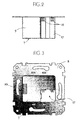
- the universal interface UI is for installation in a wall box trained and has a metallic for this purpose Support member 8 in the form of a plate or a ring on which a Flush-mounted housing 9 is attached, which is the standardized Functional part 7 contains. At the front of this housing 9 is a connector 10 for the electrical connection of the function-determining Input / output part 2 via corresponding contact elements 11.12 provided.
- Fig. 1 the function-specific input / output part 13 in the external terminal 1 installed and via a control line 14 with plug adapter 15 with the universal interface UI connected.
- Fig. 1a is the function specific Input / output part 2 directly with the universal interface UI connected and forms a kind of terminal. It. can a switch, button, dimmer, sensor or one Act display unit with which, for example Operating status of the external terminal is displayed.
- the circuit units for the coupling modules AS are in one another same housings 16 with the same main mechanical dimensions built-in.
- a receptacle 17 for a housing 16 of a Coupling module AS available in the outer wall of the standardized Functional part 7 .
- the outer walls of the housing parts have mechanical guides 18, for example dovetail guides, so that a coupling module AS with its Can insert guides in the guides of the recording.
- the electrical connection of the coupling module AS with the standardized Functional part 7 of the universal interface UI takes place via the coupling module interface IS, for which as pins 19 and sockets 20 trained contact elements are present.
- the Contact connection is made automatically when inserting a Coupling modules AS in the holder so that by inserting them of a coupling module AS the standardized functional part 7 to a mechanically and electrically completed universal interface UI is supplemented (Fig. 4, Fig. 6).
- PN and TP is one designed for coupling with the respective bus medium IM interface provided.
- the coupling via this interface IM takes place via contact elements designed as pins and sockets 21.22.
- the electrically detectable identifier (FIG. 7) contains in each coupling module AS a special type resistor R 1-n , which is part of a voltage divider R 1-n , R connected between positive potential and ground potential and whose tap A is connected to the identification line SIG.
- the identification line SIG is thus connected to a very specific DC voltage potential for each coupling module AS (LWL, TP, PN, IR, EM), which is determined by the ratio of the resistors R 1-n , R of the voltage divider.
- An A / D converter or a comparator is used to identify the respective coupling module AS.
- the microprocessor ⁇ P converts the value of the DC voltage potential on the identification line SIG into a digital value and in this way recognizes the coupling module AS that is connected via the coupling module interface IS.
- the microprocessor ⁇ P has recognized the coupling module AS, the universal interface UI is adapted for data traffic via the bus medium.
- non-wired coupling modules IR and EM are transmitting and receiving parts installed, for example optoelectric Transducers or radio transmitters and receivers (Transmitter modulator and receiver demodulator).
- the metallic is suitable as an antenna for a radio coupling module EM Support element 8 of the universal interface UI, which with a transmit output and a receive input of the coupling module EM is connected.
- a radio coupling module EM Support element 8 of the universal interface UI which with a transmit output and a receive input of the coupling module EM is connected.
- the line-independent Universal interfaces UI is a power source in the IR and EM coupling modules installed or these universal interfaces UI are powered by a separate power source.
Landscapes
- Engineering & Computer Science (AREA)
- Power Engineering (AREA)
- Selective Calling Equipment (AREA)
- Remote Monitoring And Control Of Power-Distribution Networks (AREA)
- Cable Transmission Systems, Equalization Of Radio And Reduction Of Echo (AREA)
- Programmable Controllers (AREA)
- Joining Of Building Structures In Genera (AREA)
Abstract
Description
- Fig. 1
- eine schematische Darstellung einer Anschlußeinrichtung, die ein externes Haushaltsgerät mit einem Informationsbus verbindet,
- Fig. 1a
- eine schematische Darstellung einer anderen Anschlußeinrichtung, bei der das Endgerät an dem Funktionsteil angeordnet ist,
- Fig. 2
- die Seitenansicht eines standardisierten Funktionsteiles,
- Fig. 3
- eine Frontansicht des standardisierten Funktionsteils,
- Fig. 4
- eine Frontansicht des standardisierten Funktionsteils einer Anschlußeinrichtung mit eingesetztem Kopplungsmodul,
- Fig. 5
- ein Ein-/Ausgabeteil der Anschlußeinrichtung,
- Fig. 6
- die Seitenansicht des Unterteils der Anschlußeinrichtung und
- Fig. 7
- die schematische Darstellung der elektrischen Erkennungsschaltung.
Claims (17)
- Anschlußeinrichtung für die Gebäudesystemtechnik zum Anschließen von Geräten (1,2) an einen Informationsbus (BU) mit einer busseitigen Schnittstelle (UI), die Informationen senden und empfangen kann,
dadurch gekennzeichnet,
daß die Schnittstelle (UI) ein Funktionsteil (7) und ein auswechselbares Kopplungsmodul (AS) zur Anpassung an das jeweilige Busmedium (3,4) oder die jeweilige Übertragungsart des Informationsbusses (BU) aufweist. - Anschlußeinrichtung nach Anspruch 1, dadurch gekennzeichnet, daß das Funktionsteil (7) und die Kopplungsmodule (AS) in räumlich trennbaren Gehäusen (9,16) enthalten sind.
- Anschlußeinrichtung nach Anspruch 1 oder 2, dadurch gekennzeichnet, daß mehrere Kopplungsmodule (AS) mit gleichen Baumaßen und gleichen schnittstellenseitigen Anschlußmaßen vorgesehen sind.
- Anschlußeinrichtung nach einem der Ansprüche 1 bis 3, dadurch gekennzeichnet, daß das Kopplungsmodul (AS) in einer Aufnahme (17) eines mindestens einen Teil der Schnittstelle enthaltenden Funktionsteils (7) untergebracht ist.
- Anschlußeinrichtung nach den Ansprüchen 2 und 4, dadurch gekennzeichnet, daß die Aufnahme (17) in einer Außenwand des Gehäuses (9) des Funktionsteils (7) angebracht ist.
- Anschlußeinrichtung nach einem der Ansprüche 1 bis 5, dadurch gekennzeichnet, daß jedes Kopplungsmodul (AS) eine busmediumabhängige Signaleinkopplungs- und Signalauskopplungs-Einrichtung enthält.
- Anschlußeinrichtung nach einem der Ansprüche 1 bis 6, dadurch gekennzeichnet, daß jedes Kopplungsmodul (AS) eine busmediumabhängige elektrisch detektierbare Kennung besitzt, welche von der Funktionseinheit (7) erkannt wird.
- Anschlußeinrichtung nach einem der Ansprüche 1 bis 7, dadurch gekennzeichnet, daß das Kopplungsmodul (AS) eine mit dem Übertragungsmedium koppelbare Kopplungsmodul-Schnittstelle (IM) enthält.
- Anschlußeinrichtung nach einem der Ansprüche 1 bis 8, dadurch gekennzeichnet, daß für die Kopplungsmodul-Schnittstelle (IS) als Stifte und Buchsen ausgebildete Kontaktelemente (19,20) vorgesehen sind.
- Anschlußeinrichtung nach einem der Ansprüche 1 bis 9, dadurch gekennzeichnet, daß für den Anschluß eines Kopplungsmoduls (AS) an ein Übertragungsmedium (4) als Stifte und Buchsen ausgebildete Kontaktelemente (21,22) vorgesehen sind.
- Anschlußeinrichtung nach einem der Ansprüche 1 bis 10, dadurch gekennzeichnet, daß das Kopplungsmodul (AS) eine für das jeweilige Übertragungsmedium abgestimmte Sende- und Empfangseinrichtung enthält.
- Anschlußeinrichtung nach einem der Ansprüche 1 bis 11, dadurch gekennzeichnet, daß das Kopplungsmodul (AS) einen Sendemodulator und einen Empfangsdemodulator enthält.
- Anschlußeinrichtung nach einem der Ansprüche 1 bis 12, dadurch gekennzeichnet, daß ein optisches Kopplungsmodul (AS) wenigstens einen optoelektrischen Wandler enthält.
- Anschlußeinrichtung nach einem der Ansprüche 1 bis 11, dadurch gekennzeichnet, daß ein Funkkopplungsmodul (AS) eine Sende- und Empfangsantenne enthält.
- Anschlußeinrichtung nach Anspruch 14, dadurch gekennzeichnet, daß das metallische Tragorgan (8) einer Unterputz-Anschlußeinrichtung als Antenne dient.
- Anschlußeinrichtung nach Anspruch 13 oder 14, dadurch gekennzeichnet, daß das Kopplungsmodul (AS) eine Stromquelle enthält.
- Anschlußeinrichtung nach Anspruch 1 oder 2, dadurch gekennzeichnet, daß das standardisierte Funktionsteil (7) eine Einrichtung zum Erzeugen von Telegrammen, einen Digital/Analog-Wandler, und eine Adressierungseinrichtung enthält.
Applications Claiming Priority (2)
| Application Number | Priority Date | Filing Date | Title |
|---|---|---|---|
| DE19832398 | 1998-07-18 | ||
| DE19832398A DE19832398A1 (de) | 1998-07-18 | 1998-07-18 | Anschlußeinrichtung für die Gebäudesystemtechnik |
Publications (3)
| Publication Number | Publication Date |
|---|---|
| EP0984587A2 true EP0984587A2 (de) | 2000-03-08 |
| EP0984587A3 EP0984587A3 (de) | 2003-11-12 |
| EP0984587B1 EP0984587B1 (de) | 2007-04-11 |
Family
ID=7874554
Family Applications (1)
| Application Number | Title | Priority Date | Filing Date |
|---|---|---|---|
| EP99113833A Expired - Lifetime EP0984587B1 (de) | 1998-07-18 | 1999-07-15 | Anschlusseinrichtung für die Gebäudesystemtechnik |
Country Status (3)
| Country | Link |
|---|---|
| EP (1) | EP0984587B1 (de) |
| AT (1) | ATE359637T1 (de) |
| DE (2) | DE19832398A1 (de) |
Families Citing this family (10)
| Publication number | Priority date | Publication date | Assignee | Title |
|---|---|---|---|---|
| DE20013501U1 (de) | 2000-08-04 | 2000-12-07 | Richard Hirschmann GmbH & Co., 72654 Neckartenzlingen | Schaltungsanordnung zum Anschließen eines Sensors oder Aktuators an eine Busleitung |
| DE10148543C1 (de) * | 2001-10-01 | 2003-06-05 | Housecorn Gmbh | Verteilermodul für ein Netzwerk |
| CA2365795A1 (en) * | 2001-12-21 | 2003-06-21 | Gary Pulyk | Universal serial bus to ethernet adaptor |
| DE10204809A1 (de) * | 2002-02-06 | 2003-08-14 | Insta Elektro Gmbh | Gebäudeinstallationssystem |
| DE10211938B4 (de) * | 2002-03-18 | 2016-11-10 | Sick Ag | Kopplungsvorrichtung zum Anschließen von Geräten an ein Bussystem |
| DE20209187U1 (de) | 2002-06-13 | 2002-09-19 | Sick AG, 79183 Waldkirch | Anzeigevorrichtung |
| DE102005019070A1 (de) * | 2005-04-23 | 2006-10-26 | Insta Elektro Gmbh | Gebäudeinstallationssystem |
| DE102008025095A1 (de) * | 2008-05-26 | 2009-12-17 | Resch Electronic Innovation Gmbh | Antennendose |
| NL2007077C2 (nl) * | 2011-07-11 | 2013-01-14 | Genexis Bv | Inrichting voor gebruik op de locatie van een klant van een breedband netwerk systeem, breedband netwerk systeem gebruik makend van een dergelijke inrichting en werkwijze voor de vorming van een dergelijke inrichting. |
| SE1651352A1 (en) * | 2016-10-17 | 2018-04-03 | Plejd Ab | Assembly and method for controlling electronic equipment |
Family Cites Families (4)
| Publication number | Priority date | Publication date | Assignee | Title |
|---|---|---|---|---|
| EP0263276A1 (de) * | 1986-09-09 | 1988-04-13 | BBC Brown Boveri AG | Vorrichtung zur Kopplung von Steckbaugruppen mechanisch und/oder signalmässig nicht kompatibler Bussysteme |
| DE4000623A1 (de) * | 1990-01-11 | 1991-07-18 | Merten Gmbh & Co Kg Geb | Elektrische installationseinheit fuer die hausleittechnik |
| DE19540330A1 (de) * | 1995-10-28 | 1997-04-30 | Merten Gmbh & Co Kg Geb | Elektrische Anschlußvorrichtung für die Gebäudesystemtechnik |
| DE19645626B4 (de) * | 1996-11-06 | 2009-05-20 | Abb Ag | Busgerät für den Anschluss an ein Bussystem der Gebäudesystemtechnik |
-
1998
- 1998-07-18 DE DE19832398A patent/DE19832398A1/de not_active Withdrawn
-
1999
- 1999-07-15 DE DE59914290T patent/DE59914290D1/de not_active Expired - Lifetime
- 1999-07-15 EP EP99113833A patent/EP0984587B1/de not_active Expired - Lifetime
- 1999-07-15 AT AT99113833T patent/ATE359637T1/de active
Also Published As
| Publication number | Publication date |
|---|---|
| EP0984587B1 (de) | 2007-04-11 |
| DE59914290D1 (de) | 2007-05-24 |
| EP0984587A3 (de) | 2003-11-12 |
| DE19832398A1 (de) | 2000-01-20 |
| ATE359637T1 (de) | 2007-05-15 |
Similar Documents
| Publication | Publication Date | Title |
|---|---|---|
| EP0344609B1 (de) | Digitales Signalübertragungssystem für die Hausleittechnik | |
| WO2010049299A1 (de) | Verteiler-modul bzw. damit gebildetes messsystem | |
| DE19605698C1 (de) | Anschlußeinrichtung für ein elektrisches Installationssystem | |
| DE102007048812A1 (de) | Kabelschaltung mit digitaler Signalaufbereitung | |
| EP0984587B1 (de) | Anschlusseinrichtung für die Gebäudesystemtechnik | |
| DE4425876A1 (de) | Intelligente Steckdose | |
| DE102007009552A1 (de) | Vorrichtung für die Gebäudeautomatisierung | |
| EP2426867B1 (de) | Schnittstelleneinreichtung für ein Messstellennetz | |
| DE102013102360A1 (de) | Etikettiermaschine und verfahren zum etikettieren von behältern | |
| DE68907756T2 (de) | Fernüberwachungsanordnung auf einem Fernsprechkanal für Einzel- oder Mehrzweck-Analogen. | |
| EP1320924A1 (de) | Antriebssteuerung für einen elektrischen antrieb mit sicherer elektrischer trennung von leistungsteil und regelungseinheit | |
| EP1062767A1 (de) | Computernetz mit daten- oder kommunikationsendsystemen | |
| DE4041442C1 (en) | Method of localising communication end devices - after each activation of end devices, stored position information is called up with call up procedure via serial data interface | |
| DE202019104854U1 (de) | Lichtbandsystem mit Datenübertragungsfunktion | |
| DE202012102446U1 (de) | Anordnung umfassend einen Messaufnehmer, einen Messumformer sowie eine Anzeige und/oder Bedieneinheit | |
| EP2195713B2 (de) | Gerät zum anschluss an einen bus, umrichter und verfahren zur adressierung | |
| EP0791871B1 (de) | Schalteranordnung zur An- und Abschaltung der elektrischen Energiezufuhr von elektrischen Verbrauchern | |
| EP0855816B1 (de) | Busankoppler für Anwendungsmodule der Gebäudesystemtechnik | |
| DE69027357T2 (de) | Sender und Empfänger für ein Datenverbindungssystem | |
| EP3632054A1 (de) | Bestimmung von datenbusteilnehmern eines lokalbusses | |
| DE19703160B4 (de) | Einrichtung zum Verbinden und Betreiben von Protokolliereinrichtungen in einer EIB-Anlage | |
| AT500806B1 (de) | Bausatz von leiterplatten für den anschluss von elektrischen geräten, insbesondere dimmern, transformatoren und vorschaltgeräten | |
| DE10204809A1 (de) | Gebäudeinstallationssystem | |
| DE102006051371B4 (de) | Antrieb mit Elektromotor | |
| DE10217354B4 (de) | Türstation einer Hauskommunikationsanlage |
Legal Events
| Date | Code | Title | Description |
|---|---|---|---|
| PUAI | Public reference made under article 153(3) epc to a published international application that has entered the european phase |
Free format text: ORIGINAL CODE: 0009012 |
|
| AK | Designated contracting states |
Kind code of ref document: A2 Designated state(s): AT BE CH CY DE DK ES FI FR GB GR IE IT LI LU MC NL PT SE |
|
| AX | Request for extension of the european patent |
Free format text: AL;LT;LV;MK;RO;SI |
|
| PUAL | Search report despatched |
Free format text: ORIGINAL CODE: 0009013 |
|
| AK | Designated contracting states |
Kind code of ref document: A3 Designated state(s): AT BE CH CY DE DK ES FI FR GB GR IE IT LI LU MC NL PT SE |
|
| AX | Request for extension of the european patent |
Extension state: AL LT LV MK RO SI |
|
| RIC1 | Information provided on ipc code assigned before grant |
Ipc: 7H 02J 13/00 B Ipc: 7H 01R 9/24 B Ipc: 7H 04L 12/28 A |
|
| 17P | Request for examination filed |
Effective date: 20040326 |
|
| AKX | Designation fees paid |
Designated state(s): AT BE CH CY DE DK ES FI FR GB GR IE IT LI LU MC NL PT SE |
|
| GRAP | Despatch of communication of intention to grant a patent |
Free format text: ORIGINAL CODE: EPIDOSNIGR1 |
|
| GRAS | Grant fee paid |
Free format text: ORIGINAL CODE: EPIDOSNIGR3 |
|
| GRAA | (expected) grant |
Free format text: ORIGINAL CODE: 0009210 |
|
| AK | Designated contracting states |
Kind code of ref document: B1 Designated state(s): AT BE CH CY DE DK ES FI FR GB GR IE IT LI LU MC NL PT SE |
|
| PG25 | Lapsed in a contracting state [announced via postgrant information from national office to epo] |
Ref country code: FI Free format text: LAPSE BECAUSE OF FAILURE TO SUBMIT A TRANSLATION OF THE DESCRIPTION OR TO PAY THE FEE WITHIN THE PRESCRIBED TIME-LIMIT Effective date: 20070411 |
|
| REG | Reference to a national code |
Ref country code: GB Ref legal event code: FG4D Free format text: NOT ENGLISH |
|
| REG | Reference to a national code |
Ref country code: CH Ref legal event code: EP |
|
| REG | Reference to a national code |
Ref country code: IE Ref legal event code: FG4D Free format text: LANGUAGE OF EP DOCUMENT: GERMAN |
|
| REF | Corresponds to: |
Ref document number: 59914290 Country of ref document: DE Date of ref document: 20070524 Kind code of ref document: P |
|
| PG25 | Lapsed in a contracting state [announced via postgrant information from national office to epo] |
Ref country code: SE Free format text: LAPSE BECAUSE OF FAILURE TO SUBMIT A TRANSLATION OF THE DESCRIPTION OR TO PAY THE FEE WITHIN THE PRESCRIBED TIME-LIMIT Effective date: 20070711 |
|
| PG25 | Lapsed in a contracting state [announced via postgrant information from national office to epo] |
Ref country code: ES Free format text: LAPSE BECAUSE OF FAILURE TO SUBMIT A TRANSLATION OF THE DESCRIPTION OR TO PAY THE FEE WITHIN THE PRESCRIBED TIME-LIMIT Effective date: 20070722 |
|
| PG25 | Lapsed in a contracting state [announced via postgrant information from national office to epo] |
Ref country code: PT Free format text: LAPSE BECAUSE OF FAILURE TO SUBMIT A TRANSLATION OF THE DESCRIPTION OR TO PAY THE FEE WITHIN THE PRESCRIBED TIME-LIMIT Effective date: 20070911 |
|
| NLV1 | Nl: lapsed or annulled due to failure to fulfill the requirements of art. 29p and 29m of the patents act | ||
| GBV | Gb: ep patent (uk) treated as always having been void in accordance with gb section 77(7)/1977 [no translation filed] |
Effective date: 20070411 |
|
| REG | Reference to a national code |
Ref country code: IE Ref legal event code: FD4D |
|
| EN | Fr: translation not filed | ||
| BERE | Be: lapsed |
Owner name: MERTEN G.M.B.H. & CO. KG Effective date: 20070731 |
|
| PG25 | Lapsed in a contracting state [announced via postgrant information from national office to epo] |
Ref country code: NL Free format text: LAPSE BECAUSE OF FAILURE TO SUBMIT A TRANSLATION OF THE DESCRIPTION OR TO PAY THE FEE WITHIN THE PRESCRIBED TIME-LIMIT Effective date: 20070411 Ref country code: IE Free format text: LAPSE BECAUSE OF FAILURE TO SUBMIT A TRANSLATION OF THE DESCRIPTION OR TO PAY THE FEE WITHIN THE PRESCRIBED TIME-LIMIT Effective date: 20070411 Ref country code: DK Free format text: LAPSE BECAUSE OF FAILURE TO SUBMIT A TRANSLATION OF THE DESCRIPTION OR TO PAY THE FEE WITHIN THE PRESCRIBED TIME-LIMIT Effective date: 20070411 |
|
| PLBE | No opposition filed within time limit |
Free format text: ORIGINAL CODE: 0009261 |
|
| STAA | Information on the status of an ep patent application or granted ep patent |
Free format text: STATUS: NO OPPOSITION FILED WITHIN TIME LIMIT |
|
| REG | Reference to a national code |
Ref country code: CH Ref legal event code: PL |
|
| 26N | No opposition filed |
Effective date: 20080114 |
|
| PG25 | Lapsed in a contracting state [announced via postgrant information from national office to epo] |
Ref country code: MC Free format text: LAPSE BECAUSE OF NON-PAYMENT OF DUE FEES Effective date: 20070731 Ref country code: LI Free format text: LAPSE BECAUSE OF NON-PAYMENT OF DUE FEES Effective date: 20070731 Ref country code: IT Free format text: LAPSE BECAUSE OF FAILURE TO SUBMIT A TRANSLATION OF THE DESCRIPTION OR TO PAY THE FEE WITHIN THE PRESCRIBED TIME-LIMIT Effective date: 20070411 Ref country code: GR Free format text: LAPSE BECAUSE OF FAILURE TO SUBMIT A TRANSLATION OF THE DESCRIPTION OR TO PAY THE FEE WITHIN THE PRESCRIBED TIME-LIMIT Effective date: 20070712 Ref country code: GB Free format text: LAPSE BECAUSE OF FAILURE TO SUBMIT A TRANSLATION OF THE DESCRIPTION OR TO PAY THE FEE WITHIN THE PRESCRIBED TIME-LIMIT Effective date: 20070411 Ref country code: FR Free format text: LAPSE BECAUSE OF FAILURE TO SUBMIT A TRANSLATION OF THE DESCRIPTION OR TO PAY THE FEE WITHIN THE PRESCRIBED TIME-LIMIT Effective date: 20071207 Ref country code: CH Free format text: LAPSE BECAUSE OF NON-PAYMENT OF DUE FEES Effective date: 20070731 |
|
| PG25 | Lapsed in a contracting state [announced via postgrant information from national office to epo] |
Ref country code: BE Free format text: LAPSE BECAUSE OF NON-PAYMENT OF DUE FEES Effective date: 20070731 |
|
| PG25 | Lapsed in a contracting state [announced via postgrant information from national office to epo] |
Ref country code: FR Free format text: LAPSE BECAUSE OF FAILURE TO SUBMIT A TRANSLATION OF THE DESCRIPTION OR TO PAY THE FEE WITHIN THE PRESCRIBED TIME-LIMIT Effective date: 20070411 |
|
| PG25 | Lapsed in a contracting state [announced via postgrant information from national office to epo] |
Ref country code: CY Free format text: LAPSE BECAUSE OF FAILURE TO SUBMIT A TRANSLATION OF THE DESCRIPTION OR TO PAY THE FEE WITHIN THE PRESCRIBED TIME-LIMIT Effective date: 20070411 |
|
| PG25 | Lapsed in a contracting state [announced via postgrant information from national office to epo] |
Ref country code: LU Free format text: LAPSE BECAUSE OF NON-PAYMENT OF DUE FEES Effective date: 20070715 |
|
| PGFP | Annual fee paid to national office [announced via postgrant information from national office to epo] |
Ref country code: AT Payment date: 20130626 Year of fee payment: 15 |
|
| REG | Reference to a national code |
Ref country code: AT Ref legal event code: MM01 Ref document number: 359637 Country of ref document: AT Kind code of ref document: T Effective date: 20140715 |
|
| PG25 | Lapsed in a contracting state [announced via postgrant information from national office to epo] |
Ref country code: AT Free format text: LAPSE BECAUSE OF NON-PAYMENT OF DUE FEES Effective date: 20140715 |
|
| PGFP | Annual fee paid to national office [announced via postgrant information from national office to epo] |
Ref country code: DE Payment date: 20170711 Year of fee payment: 19 |
|
| REG | Reference to a national code |
Ref country code: DE Ref legal event code: R119 Ref document number: 59914290 Country of ref document: DE |
|
| PG25 | Lapsed in a contracting state [announced via postgrant information from national office to epo] |
Ref country code: DE Free format text: LAPSE BECAUSE OF NON-PAYMENT OF DUE FEES Effective date: 20190201 |