EP0984614A2 - Elektronische Kamera mit Sucherbild-Aufzeichnungs-Funktion - Google Patents
Elektronische Kamera mit Sucherbild-Aufzeichnungs-Funktion Download PDFInfo
- Publication number
- EP0984614A2 EP0984614A2 EP99117045A EP99117045A EP0984614A2 EP 0984614 A2 EP0984614 A2 EP 0984614A2 EP 99117045 A EP99117045 A EP 99117045A EP 99117045 A EP99117045 A EP 99117045A EP 0984614 A2 EP0984614 A2 EP 0984614A2
- Authority
- EP
- European Patent Office
- Prior art keywords
- image
- display
- past
- finder
- shooting
- Prior art date
- Legal status (The legal status is an assumption and is not a legal conclusion. Google has not performed a legal analysis and makes no representation as to the accuracy of the status listed.)
- Granted
Links
Images



Classifications
-
- H—ELECTRICITY
- H04—ELECTRIC COMMUNICATION TECHNIQUE
- H04N—PICTORIAL COMMUNICATION, e.g. TELEVISION
- H04N1/00—Scanning, transmission or reproduction of documents or the like, e.g. facsimile transmission; Details thereof
- H04N1/21—Intermediate information storage
- H04N1/2104—Intermediate information storage for one or a few pictures
- H04N1/2112—Intermediate information storage for one or a few pictures using still video cameras
- H04N1/2125—Display of information relating to the still picture recording
-
- H—ELECTRICITY
- H04—ELECTRIC COMMUNICATION TECHNIQUE
- H04N—PICTORIAL COMMUNICATION, e.g. TELEVISION
- H04N23/00—Cameras or camera modules comprising electronic image sensors; Control thereof
- H04N23/60—Control of cameras or camera modules
- H04N23/63—Control of cameras or camera modules by using electronic viewfinders
- H04N23/631—Graphical user interfaces [GUI] specially adapted for controlling image capture or setting capture parameters
- H04N23/632—Graphical user interfaces [GUI] specially adapted for controlling image capture or setting capture parameters for displaying or modifying preview images prior to image capturing, e.g. variety of image resolutions or capturing parameters
-
- H—ELECTRICITY
- H04—ELECTRIC COMMUNICATION TECHNIQUE
- H04N—PICTORIAL COMMUNICATION, e.g. TELEVISION
- H04N1/00—Scanning, transmission or reproduction of documents or the like, e.g. facsimile transmission; Details thereof
- H04N1/21—Intermediate information storage
- H04N1/2104—Intermediate information storage for one or a few pictures
- H04N1/2112—Intermediate information storage for one or a few pictures using still video cameras
-
- H—ELECTRICITY
- H04—ELECTRIC COMMUNICATION TECHNIQUE
- H04N—PICTORIAL COMMUNICATION, e.g. TELEVISION
- H04N23/00—Cameras or camera modules comprising electronic image sensors; Control thereof
- H04N23/60—Control of cameras or camera modules
- H04N23/63—Control of cameras or camera modules by using electronic viewfinders
- H04N23/633—Control of cameras or camera modules by using electronic viewfinders for displaying additional information relating to control or operation of the camera
- H04N23/635—Region indicators; Field of view indicators
-
- H—ELECTRICITY
- H04—ELECTRIC COMMUNICATION TECHNIQUE
- H04N—PICTORIAL COMMUNICATION, e.g. TELEVISION
- H04N5/00—Details of television systems
- H04N5/76—Television signal recording
- H04N5/765—Interface circuits between an apparatus for recording and another apparatus
- H04N5/77—Interface circuits between an apparatus for recording and another apparatus between a recording apparatus and a television camera
- H04N5/772—Interface circuits between an apparatus for recording and another apparatus between a recording apparatus and a television camera the recording apparatus and the television camera being placed in the same enclosure
Definitions
- the present invention relates to an electronic camera and a control method for shooting with the same.
- the present invention relates to an electronic camera which can display a finder image and a control method for shooting with the same.
- an electronic still camera (hereinafter referred to as a digital camera or the like), which is one kind of an electronic camera
- a shooting mode when a shooting mode is set, an optical image of a subject is converted to an electric signal by an image pick-up element, image data obtained after image processing such as signal conversion and color process are not only taken in a working memory but simultaneously transferred to a display section and further the data transferred to the display section is subjected to image reconstruction by a video encoder, thereby displaying a through-(finder)-image (dynamic image) on a liquid crystal display.
- image data which has been taken in a working memory at a time point of the operation of a shutter button are not only presented on a liquid crystal display as a shot image in a still state, but also recorded in a retention-recording memory after the image data is compressed.
- an electronic camera according to the present invention comprises:
- an electronic camera according to the present invention comprises:
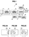
- FIG. 1 is a block diagram showing an embodiment of a circuit configuration of a digital camera (electronic still camera) to which a through-image (finder image) retrieving method of the present invention is applied.
- a digital camera 100 comprises: an optical system 11, a signal converting section 12; a signal processing section 13; a DRAM (Dynamic Random Access Memory) 14; a control section 20; an operator section 30; a display section 40; a flash memory 50; and a power supply 90.
- DRAM Dynamic Random Access Memory
- the optical system 11 includes photographic lenses 111; an automatic diaphragm control mechanism (not shown) and the like, wherein light rays of a subject collected by way of the photographic lenses 111 are focused on an image pick-up element (CCD, i.e., Charge Coupled Device) at the later stage 12.
- CCD Charge Coupled Device
- the signal converting section 12 includes the CCD, a signal converting circuit and the like, converts an image focused on the CCD through the optical system 11 into an electric signal, and outputs the converted electric signal into the form of digital data having a prescribed period.
- the signal processing section 13 processes the output from the signal converting section 12 in an ordinary still-image shooting mode to obtain signal components including a luminance-color difference multiplex signal (Y, Cb, Cr data) in the digital form, and transfers the Y, Cb, Cr data (hereinafter referred to as image data) to the DRAM 14 so as to temporarily store it.
- image data which are taken in are sent to the display section 40 intermittently. It is alternatively allowed that image data which are sequentially stored into the DRAM 14 are read out and sent to the display section 40 to display through images.
- the signal processing section 13 further reads out image data which are written in the DRAM 14 in recording for retention of an image by a shutter operation, applies the JPEG (Joint Photographic Expert Group) compression to image data.
- JPEG Joint Photographic Expert Group
- the signal processing section 13 further applies data expansion to image data which are recorded for retention in a recording memory (flash memory) 50 to write resulted data into the DRAM 14.
- the control section 20 has a microprocessor architecture comprising CPU (Central Processing Unit); RAM (Random Access Memory); program storing ROM (Read Only Memory); a timer; and the like.
- the CPU is connected to the above-described circuits and a power supply switch not shown and the like by way of a bus line.
- the CPU controls the entire digital camera 100 based on control programs stored in the program storing ROM, and executes functions of the digital camera 100, for example, an ordinary shooting, regeneration of a recorded image, shooting by through-image retrieval in a through-image retrieving mode and the like on the basis of corresponding mode processing programs read out from the program storing ROM according to state signals from the operator section 30.
- the operator section 30 comprises switches and buttons such as a processing mode change-over switch, a function selecting button, a power supply switch, a shutter button 36, a record regenerating mode selecting button, and the like.
- switches and buttons When the switches and buttons are operated, state signals are sent to the control section 20.
- the shutter button 36 in the embodiment, is provided with a function to switch to a through-image retrieving mode in one action when a shutter chance has been lost in shooting (FIG. 3).
- a through-image retrieving button 37 which is dedicated for selecting a through-image retrieving mode may separately be provided next to the shutter button 36.
- the display section 40 comprises an video encoder, VRAM (Video RAM), LCD (Liquid Crystal display) and the like.
- VRAM Video RAM
- LCD Liquid Crystal display
- Various images such as a through image in a shooting mode, a regenerative image in regenerating mode, a selection menu in a processing selecting mode, guides (or icons) are displayed on the LCD and, in addition, a past through-image in a through-image retrieving mode is displayed.
- the flash memory 50 stores an image data from the signal processing section 13. Besides, in the flash memory 50, an area for recording the image data is secured and an image data register list information (not shown) is stored, in which, when image data are stored, information of a shooting mode, shooting conditions and the like of the image is registered.
- an image data register list information (not shown) is stored, in which, when image data are stored, information of a shooting mode, shooting conditions and the like of the image is registered.
- a memory card which is freely mountable/demountable to the camera body may be employed instead of the flash memory.
- FIGS. 2A, 2B and 2C are schematic illustrations for a through-image retrieving method.
- an image 216 (hereinafter referred to a present through-image) is displayed as shown in FIG. 2A.
- past though-images may sequentially be displayed at prescribed intervals, while switching, starting an oldest image, till the present through-image 216 displayed at the time point when a user has wrongly pressed the shutter button 36.
- the shutter chance should be between the through-image 201 at a time point immediately before the switching to the through-image retrieving mode and a through image 216 at a time point when the user wrongly presses the shutter button 36. Therefore, the user can obtain a through image 210 at the shutter chance among past through images which are sequentially displayed.
- a method of the present invention can make it possible to achieve a shoot start timing by retrieving past through-images, not only when a user overlooks a shutter timing or wrongly takes a shutter chance in a so-called ordinary shooting in a single shot operation mode (first embodiment) wherein images are picked up and recorded one frame at a time by shutter operations, but also when a user wrongly takes a start timing for shooting a continuous shooting (dynamic image shooting) with deviation in time, in which a plurality of images are continuously shot by a shoot start instruction (second embodiment).
- a time length of retrieval of past through-images starting from a present through image is set to 3 sec, that is, a display time length for 16 through-images, the through-image display interval and the retrieval time period are not limited to the above described values, but may freely be determined in a proper manner in designing according to a performance and a type of a digital camera.
- a shutter button and a switching button to a through-image retrieving mode are arranged adjacent to each other so that a switching operation is easy to be performed.
- a shutter button 36 with which switching to the though-image retrieving mode can be performed in one action is used.
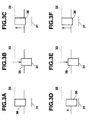
- FIGS. 3A to 3F are illustrations of an operation of a shutter button which alone makes switching to a through-image retrieving mode possible.
- FIG. 3A shows a state of the shutter button 36 which is not pressed.
- a mark 31 indicates a contact position
- a mark 32 indicates an original position to which the top of the shutter button 36 returns.
- FIG. 3B shows a state in which the shutter button 36 is forced downward by the finger or the like to reach the contact position 31, that is, where the shutter button 36 is fully pressed downward.
- the switch is on.
- image data when the shutter operation is conducted (G13 of FIG. 5) is taken out from the DRAM 14 and is displayed on the display section 40 as a still image in order to confirm a shot image.
- a record instructing signal is sent to the control section 20.
- the control section 20 performs image record processing wherein image data in the DRAM 14 corresponding to a still image in display is compressed in the signal processing section 13 to be stored in the flash memory 50.
- a present through-image (G13 of FIG. 5) is an image at the shutter chance.
- the embodiment is an example of retrieval of through-images in a so-called ordinary shooting mode in which images are picked up and recorded one at time by shutter operations and will be described based on FIGS. 1 to 5 and flow charts of FIGS. 6A and 6B.
- FIG. 4 is an illustration for a layout example of a DRAM 14 of a digital camera 100 and shows a layout in the ordinary shoot mode when an image of one frame in size is picked up.
- Areas G1 to G16 which are secured in the DRAM 14 in FIG. 4 are storage areas for image data which are taken in at prescribed intervals. Further, an area indicated by a reference numeral 1417 is a working area and an area indicated by a reference numeral 1418 is a reserved area.
- storage areas for image data are set to 16 areas G1 to G16 for the sake of convenience of description, but there is no limitation to this figure, but areas in number more or less than 16 areas may be adopted. That is, the number of storage areas which are required for a digital camera in designing in terms of a performance of a type thereof is only necessary.
- FIG. 5 is an illustration for a relation between present and past through-images.
- G13 is an area where image data corresponding to a present through-image when the shutter operation is conducted are stored
- G16 is an area where image data corresponding to a through-image obtained when a through-image retrieving operation is conducted are stored
- G1 is an area where image data corresponding to a past through-image picked up in the earliest time point in a through-image retrieving operation (in the embodiment, a through-image data 3 seconds before is stored) are stored.
- G10 is an area where image data at the desired shutter chance are stored.
- a present through-image is stored in an area G16 and a past through-image picked up at the earliest time point is stored in G1
- a series of operations are repeated in which when the most recent image is stored in the DRAM 14, all the images stored in the areas G1 to G16 are respectively shifted by one area to adjacent areas and thereby the earliest image data stored in G1 is erased, and the newest image is written in the empty G1.
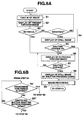
- FIG. 6A is a flow chart showing an operation example of the control section 20 including through-image retrieval in an ordinary shoot mode.
- subject images are taken in at intervals of 0.2 second and a time of retrieval is set to 3 seconds.
- Step 1 Take-in of Image
- Step 2 Display of Through-Image
- Unnecessary part of image data which are taken in at intervals of 0.2 second are removed in the signal processing section 13 and immediately thereafter displayed on a screen of the display section 40 as a real time image, that is, as a present through-image.
- the display is of dynamic images. Accordingly, the user can await a shutter chance using a display screen as a finder.
- Step 53 Operation When Shutter Chance is Overlooked
- Step S5 Confirmation of Shutter Chance and Shutter Operation
- Step S6 Display of Retrieved Through-Image
- past through-images (G1 to G16 of FIG. 5) in the past till 3 seconds before a present through-image obtained when switching to the through-image retrieving mode is effected are sequentially displayed starting from a past through-image picked up the earliest time point (G1 of FIG. 5). For example, when through-images are displayed while switching at intervals of 0.2 second which is same as the take-in interval of image data, past through-images picked up in the past till 3 seconds before a present time are always displayed.
- Step S7 Second Shutter Operation
- step S8 When the user sees past through-images and presses the shutter button 36 which is suspended at a half way position down to the contact position 31, a past through-image in display at the time point is shot and program goes to step S8.
- program flow returns to step S6 and display of past through-images is continued.
- image recording of step S9 may be started at a time when the shutter button is fully pressed while the user does not await till the shutter button 36 restores its original position 32.
- Step S8 Display of Still Image
- step S7 When the full-press shutter operation is conducted in the step S7, the control section 20 continues to display a past through-image which is displayed on the display section 40 at the time point of the shutter operation without any change as a still image. Thereafter program flow goes to step S9.
- control section 20 regards a still image displayed in step S4 or S8 as at the shutter chance and sends image data in the DRAM 14 corresponding to the still image in display to the signal processing section 13 to compress the image data, and further makes the flash memory 50 store the data. Thereafter, program flow returns to step S1 and a present through-image display state is recovered.
- the shutter button 36 can switch a mode to a through-image retrieving mode
- a through-image retrieving mode switching button 37 is provided in the vicinity of the shutter button 36 and when the switching button 37 is operated, a trigger signal is sent out to the control section 20 and thereby, making the through-image retrieving mode effective, as a result of switching.
- FIG. 6B is a flow chart showing an operation example of the control section 20 which is an alternative of step S5 of FIG. 6A, in a case where the retrieving mode switching button 37 is separately arranged.
- step S5' it is judged whether or not a prescribed time period has elapsed after a shooting instruction by an operation of the shutter button 36 in step S4 is issued.
- step S5'' it is judged whether or not the retrieving mode switching button 37 has been operated.
- program flow goes to step S6 and a past through-image is displayed on the screen of the display section 40.
- step S4 a shooting instruction is issued and image recording by step S9 of image data displayed as a still image is not conducted due to cancellation.
- step S5' if it is judged that the prescribed time length has elapsed, program flow goes to image recording of step S9, in step S4 a shooting instruction is issued and image recording of image data displayed as a still image is executed.
- step S3 it is judged whether or not the retrieving mode switching button 37 is operated.
- step S9 image recording (step S9) of image data at the time point when the instruction is issued is executed; and when the retrieving mode switching button 37 is operated within a prescribed time period after the issuance of the shooting instruction, image data which are recorded for retention in image recording are erased or the image data are designated as a recording (overwriting) position of image data picked up by the next shooting instruction.
- step S4 when the shutter button 36 is pressed down and thereafter the shutter button 36 is again fully or half way pressed down within a prescribed time period (for example 1 second) while the through-image retrieving mode switching button 37 is not provided, as a result, a trigger signal is sent out to the control section 20 to switch a mode to the through-image retrieving mode.
- a prescribed time period for example 1 second
- a display switch interval of past through-images is the same as an image take-in interval (image pick-up interval), that is, a display switch interval of present through-images
- the display switch interval of past through-images may be set longer than that of the present through-images in order to prevent it from occurring to lose a second shutter chance.
- the embodiment is an example of through-image retrieval in a so-called ordinary shooting mode in which images are picked up one at a time by shutter operations.
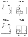
- FIGS. 7A and 7B are illustrations showing an example of through-image display and through-image retrieving display.
- a through-image display is presented on one image on one screen basis as shown in FIGS. 2A-2C
- a down-sized past through-image is presented on part of a present through-image in a superimposing manner as shown in FIG. 7A when through-images are displayed.
- a down-sized present through-image is presented on part of past through-images sequentially presented while retrieving.
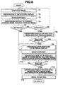
- FIG. 8 is a flow chart showing an operation example of the control section 20 in a case where down-sized another through-image occurring in time sequence is displayed on part of a through-image in the through-image retrieval in the ordinary shoot mode.
- a take-in interval of subject images is set to 0.2 second and a retrieval time is set to 3 seconds in the second embodiment in a similar manner to the first embodiment.
- a method for cyclically storing taken-in image data in the DRAM 14 is adopted, in which all images stored in the areas G1 to G16 are respectively shifted to adjacent areas each time when a new image data is written in and thereby, a present through-image is always stored in the area G16 and a past through-image picked up at the earliest time point is always stored in the area G1.
- Step T1 Take-in of Image
- image data simultaneously taken in at intervals of 0.2 second are sequentially stored in the working area 1417 of the DRAM 14 after removing unnecessary part thereof in the signal processing section 13 as a present through-image updating the previous present through-image. That is, image data which are similar to image data which are sequentially stored in the area G16 are sequentially stored in the working area 1417 updating the previous image data.
- Image data in the past 3 seconds before a present time are sequentially compressed and superimposed for synthesis on image data after removing unnecessary part thereof which are sequentially stored in the working area 1417 of the DRAM 14 in step T2 while updating the previous image data. That is, image data in the storage area G1 picked up at the earliest time point are compressed and superimposed for synthesis as a past through-image on image data after removing unnecessary part thereof, which are stored in the working area 1417 as a present through-image in the step T2, each time when image data are taken in to the storage area G16 for a present image.
- Step T4 Display of Through-image as Synthetic Image
- synthetic image data stored in the working area 1417 of the DRAM 14 are sent to the display section 40 to display through-images on the screen at intervals of 0.2 second.
- a present through-image G'16 which is taken in is displayed in frame size and a past image G'1 at the earliest time point from a present though-image is displayed on the top left part of the present through-image G'16 as a past through-image in a superimposed and synthesized manner.
- through-images are sequentially displayed at very short intervals and therefore, the images are dynamically presented.
- a user can use a display image as a finder and can not only correctly await a shutter chance but also simultaneously see a past through-image.
- Step T5 Operation When Shutter Chance is Overlooked
- the user When the user finds that he or she has lost a shutter chance without conducting a shutter operation while retaining a subject in the field of view, the user stops the shutter button on the way of pressing down without pressing down to the full extent, but to place the shutter button in a half pressed state. With the shutter button in the half-pressed state, the digital camera comes in a through-image retrieving mode and program flow goes to step T8.
- Step T6 Image Pick-up
- the switch is on.
- update recording of image data to the working area 1417 in the DRAM 14 is suspended and image data in the working area are fixed, as they are when the shutter operation is conducted.
- fixation a still image which is a shot image and a past through-image which are down-sized are displayed on the screen of the display section 40 with the past through-image superimposed on the still image.
- program flow returns to step T1. That is, subject images are taken in and present and past through images are sequentially displayed till the shutter button 36 is pressed down.
- Step T7 Confirmation of Shutter Chance and Shutter Operation
- Step T8 Preparation for Switching to Retrieval display
- image data corresponding to a present through-image displayed at a time point when the shutter button 36 is pressed down half way in step T5 or a shot image displayed as a still image in step T6 are compressed to store in the working area 1417 of the DRAM 14.
- Past image data in the past 3 seconds before a present time that is, image data in the storage area G1 are sequentially processed to remove unnecessary part thereof and synthesized with compressed image data (still image data) stored in the working area 1417 of the DRAM 14.
- image data of a present through-image displayed at a time point when the shutter button 36 is pressed down half way in step T5 or when the shutter button 36 is fully pressed down in step T6 are compressed and the compressed image data are superimposed for synthesis on a past through-image in the past 3 seconds before the present through-image. Thereafter, in the same manner, still image data compressed and past image data which shift at 0.2 second intervals are synthesized with each other.
- Step T10 Through-image Display after Shutter Chance Retrieval
- the synthesized image is sent to the display section 40 and a past through-image is displayed on the screen.
- G1' of an image of 3 seconds before is displayed in one frame size and a compressed image of a present through-image when the shutter button is pressed down is displayed on a past through-image in the top left part of the image G'1 in a superimposing manner (in a synthetic state).
- a user uses a display screen as a finder and can again await a shutter chance while referring to a present through-image displayed at a time point when a mode is switched to the retrieving mode, or a shot still image which is shot by a shutter operation, that is, an image for which a shutter chance has not been caught.
- Step T11 Second Shutter Operation
- Step T12 Still Image Display
- the control section 20 takes out image data stored in the area G1 of the DRAM 14 at a time point when a shooting instruction is issued, that is, image data corresponding to a past through image displayed at a time point when the shutter button is pressed down, and sent out to the display section 40 to present a still image thereof on the screen of the display section 40. Thereafter, program flow goes to step T13.
- an image a compressed image + a past through-image
- the display may be regarded as a still image display.
- control section 20 regards a still image displayed in one frame size in the step T6 or T10 as an image of a shutter chance and sends image data in the DRAM 14 corresponding to the still image to the signal processing section 13 to compress and store in the flash memory 50. Thereafter, program flow returns to step T1 and a display state presenting present and past through images is restored.
- a present through-image may be displayed as a down-sized image together with a past through-image.
- step T10 when program flow comes to the step from step T5, a present through-image may be displayed as a down-sized image together with a past through-image and when program flow comes to the step from step T7, a shot still image may be displayed as a down-sized image together with a past through-image. That is, an image which is displayed in one frame size before a mode is changed to the through-image retrieving mode may be displayed as a down-sized image and an image which is displayed as a down-sized image may be displayed as a one frame image.
- step T12 While in step T12, a down-sized still image at a time point when the shutter button is pressed down (step T5 and T6) is displayed together with a shot still image which is given a shoot instruction in step T11, only the shot still image may be displayed or the shot still image and the present through image which is down sized may be displayed.
- present and past through-images are respectively displayed in different image sizes, for example as shown in FIG. 9B, present and past through images may be displayed in the same size.
- FIGS. 9A and 9B are examples showing a through-image display.
- switching to the through-image retrieving mode is made possible and thereby, present and past through-images are displayed in a switching manner so that the present and past through-images can selectively be shot.
- the present and past through-images both may be always displayed and thereby the present and past through-images can selectively be shot with no switching to the through-image retrieving mode.
- the present through-image is displayed in one frame size and a down-sized past through image is displayed in a superimposing manner on the present through-image and, further alternatively as in FIG. 9B, the screen is halved into left and right halves and a 1/2-sized past through-image is displayed on the left half screen and a 1/2-sized present through-image is displayed on the right half screen.
- the screen is halved into upper and lower halves and the past and present through-images are respectively displayed on the half-sized screens.
- FIG. 10 a flow chart of FIG. 10 will be described based on FIGS. 1, 3 to 5 and 9A and 9B.
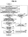
- FIG. 10 is a flow chart showing an operation example of the control section 20 in which past and present through-images are constantly simultaneously displayed in a through-image retrieval in an ordinary shooting mode and present and past images are selectively shot by adopting different shoot instructing methods.
- a take-in time of subject images is set to 0.2 second and a retrieval interval is set to 3 seconds.
- a method for cyclically storing image data in the DRAM 14 is similar to that of the second embodiment.
- the shutter button 36 is a shutter button for shooting a present through-image and the through-image retrieving mode-switching button 37 is a shutter (shooting instructing) button for shooting a past through-image.
- image data which are taken in at 0.2 second intervals are partly removed to eliminate unnecessary part and stored in the working area 1417 of the DRAM 14.
- image data when image data are taken in the area G16 at 0.2 second intervals, the image data are partly removed to eliminate unnecessary part and sequentially stored in the working area 1417 as a present through-image while updating.
- image data which are taken in at 0.2 second intervals are sequentially compressed in the signal processing section 13 to store in the working area 1417 of the DRAM 14.
- image data are sequentially compressed in 1/2 size and sequentially stored in the working area 1417.
- image data in the past a prescribed time period before an image which is sequentially taken in the area G16 are down-sized in a prescribed size and synthesized with image data (a present through-image), which are stored in the working area 1417 of the DRAM 14 in step U2, and which are partly removed to eliminate unnecessary part.
- Step U4 Display of Through Image: Synthesized Image
- a synthesized image data are sent to the display section 40 and present and past through-images are displayed.
- through-images are sequentially displayed at very short intervals, the images are dynamically presented. Accordingly, a user uses a display screen as a finder and can not only await a shutter chance but also simultaneously see a past through-image.
- a present image G'16 is displayed in one frame size and a past image G'1 which is down-sized is displayed on the top left part thereof being superimposed on (or being synthesized with) the image G'16.
- a past image G'1 which is down-sized in 1/2 size is displayed on the left half and a present image G'16 which is down sized in 1/2 size is displayed on the right half.
- Step U5 Shooting of Present Through-image
- Step U6 Display of Present Still Image
- step U5 when a shooting instruction for a present image is issued, the control section 20 takes out, as a shot still image, present image data taken in the area G16 of the DRAM 14 at a time point when the shoot instruction is issued; stored in the working area 1417; at the same time, sequentially compress a past through-image; synthesizes the compressed image with the shot still image data by performing a similar processing to that of step U3 and starts display of a synthetic image on the screen of the display section 40. Thereafter, program flow goes to step U7.
- a shot still image is displayed on the right half screen and a past through-image is displayed on the left half screen.
- step U4 dynamic display of the present through-image is ceased to be presented and a still image thereof is displayed.
- Step U7 Shooting of Past Through-image
- step U6 When a user confirms a shot still image whose display gets started in step U6 and if the user judges that the image is not an image at a shutter chance, the user awaits a second shutter chance while watching past through-images which are simultaneously displayed and presses the shutter button 37 for a past shooting when the shutter chance comes.
- the user presses the shutter button 37 a shooting instruction is issued for a past through-image which is displayed at the time point when the shutter button 37 is pressed down and program flow goes to step U11.
- Step U8 Passage of Prescribed Time Period
- program flow if it is judged that the prescribed time period has not elapsed, program flow returns to step U7 and when the prescribed time period has elapsed, program flow goes to step U9.
- Step U9 Present Image Recording
- step U8 when it is judged that the prescribed time period has elapsed after the shutter button 36 is operated, the control section 20 sends a present image data which is taken out as a shot image in the step U6 while regarding a shot still image which is displayed as one picked up at a shutter chance to the signal processing section 13 to compress the image data, records the image data in the flash memory 50 and then, the processing is terminated. Thereafter, program flow returns to step U1 and a display state presenting present and past through-images is restored.
- Step U10 Shooting of Past Through-image
- Step U11 Display of Past Still Image
- step U7 or U10 when a shooting instruction for a past through-image is issued, the control section 20 takes out, as a shot still image, past image data which are stored in the area G1 of the DRAM 14 at the time point when the shooting instruction is issued and sends the still image to the display section 40 to display the still image on the screen of the display section 40. Thereafter, program flow goes to step U12.
- step U10 the control section 20 sends past image data taken out in the step U11 as a shot image while regarding a shot still image which is displayed as one at a shutter chance to the signal processing section 13 to compress the image data and the image data are then stored in the flash memory 50. Thereafter the processing is terminated and then program flow returns to step U1.
- the shutter button 36 for present shooting and the shutter button 37 for past shooting are separately provided, different methods for respectively operating one shutter button for present shooting and past shooting may be applied to the one shutter button (for example, in the case of present shooting, full pressing-down is applied while in the case of past shooting, half pressing-down is applied).
- step U7 when the shutter button 37 for past shooting is operated, program flow goes to step U11, when the shutter button 36 which is the same as one for present shooting is twice operated within a prescribed time period after a shooting instruction is issued in step U5, program flow may go to step U11.
- step U5 when a shooting instruction is issued by an operation of the shutter button 36 for present shooting, image recording (step U9) of image data at a time point of the shooting instruction is executed and when the shutter button 37 for past shooting is operated within a prescribed time period after the shoot instruction, image data which is recorded for retention by image recording is erased, or the image data is set as a recording (overwrite) position for image data which are picked up in the next shoot instruction.
- step U6 only a shot still image may be displayed without display of past through-image.
- step U11 while only a shot still image is displayed, a present through-image may simultaneously be displayed.
- a down-sized present through-image is displayed on a still image display in a superposing manner and in the example of FIG. 9B, a shot still image is displayed on the left half screen and a present through-image is displayed on the right half screen.
- FIG. 11 is an illustration showing an example of a layout of a working memory (DRAM 14) adopted in a case where the present invention is applied to a continuous (dynamic image) shooting mode, in which a plurality of images are continuously shot by a single shutter operation.
- DRAM 14 working memory
- areas G1 to G32 secured on the DRAM 14 are storage areas for image data taken in at prescribed intervals. Further, an area indicated by a reference numeral 1417' is a working area and an area indicated by a reference numeral 1418' is a reserved area.
- storage areas for image data include the 32 areas G1 to G32, the number of storage areas is not limited to 32, but the number may be more or less than 32. That is, the number of storage areas may be the number required in designing in terms of a performance of a type of the digital camera.
- 16 images are continuously shot by a single operation of the shutter button 36 and the images are stored in the flash memory 50, when a user overlooks a shoot start timing without shutter operation, or when a shoot start timing is mistakenly recognized and conducts a wrong shutter operation, there is a chance in which the user loses the start timing for continuous shooting.
- a continuous shooting interval is set to 0.2 second, but an interval is not limited to this and may be shorter than 0.2 second. That is, a continuous shooting interval may be an interval required in designing in terms of a performance of a type of the digital camera.
- FIGS. 12A to 12D are illustrations for through-image retrieval in the continuous shooting mode.
- images in the past a prescribed time period for example 6.2 seconds before are displayed as past images in the form of a through-image.
- the number of continuously shot images is set to 16 from the viewpoint of convenience in description
- images in the number more or less than 16 may be employed. That is, the number of images in the continuous shooting mode may be the number required in designing in terms of a performance of a type of the digital camera 100.
- the number of images stored in the DRAM 14 is set to 32 for the sake of convenience in description, the number is not limited to this number either, but the number more or less than 32 may be set. That is, the number of images stored in the DRAM 14 may be more than the number of continuously shot images, or alternately may be less than that since images which are taken in after a retrieval timing can successively used.
- FIG. 13 is a flow chart showing an operation example of the control section 20 including a through-image retrieval operation in the continuous shooting mode.
- a take-in interval is set to 0.2 second and a retrieval time period is set to 6.2 seconds (corresponding to 31 images).
- Step V1 Take-in of Image
- Step V2 Display of Through-image
- image data which are taken in at 0.2 second intervals are partly removed to eliminate unnecessary part and immediately displayed on the screen of the display section 40 as a present through-image.
- through-images are sequentially displayed at very short intervals, the images are dynamically presented. Therefore, a user employs a display screen as a finder and can await a continuous shoot start timing.
- Step V3 Operation in Overlooking of Continuous Shoot Start Timing
- Step V4 Continuous Shooting Start
- continuous shoot start image may be displayed on a screen of the display section 40 as a still image.
- program flow returns to step V1 (that is, image data are taken in at 0.2 second intervals and through-images are sequentially displayed till the shutter button 36 is pressed down).
- Step V5 Confirmation of Continuous Shoot Timing and Shutter Operation
- Step V6 Display of Retrieved Through-images
- step V3 or V5 when a mode is switched to the through-image retrieving mode, past through-images are sequentially displayed with an image in the past 6.2 sec before a present image at a time point of the mode switching as an image picked up at the earliest time point.
- Step V7 Second Operation of Shutter
- Step v8 Still Image Display
- step V7 when the shutter is operated in a fully pressed condition, the control section 20 takes out image data corresponding to a past through-image displayed at the time point of the shutter operation among image data taken in the DRAM 14 and sends the data to the display section 40 to display a still image thereof on the screen thereof. Thereafter, program flow goes to step V9.
- step V5 or V7 when a user restores the shutter button 36, which has been pressed down to the contact position 31, to its original position 32, the control section 20 sequentially sends image data of 16 image (till G23 in the example of FIG. 12D) starting from the area Gi (area G8 in the example of FIG. 12A) in a corresponding continuous shoot start timing Dt to the signal processing section 13 to compress the image data one image at a time and records the image data in the flash memory 50, in which operations till 16 images are repeated. When the operations are completed, the processing is terminated.
- program flow returns to step V1 and a display state of present and past through-images are restored.
- the present invention can also be applied to a video movie camera and the like which makes it possible to shoot dynamic images for a long time (for example 60 min).
- a shooting instruction of steps T6 and T11 in the flow chart of FIG. 8 may be a continuous shoot start instruction
- displays of steps T6 and T10 may be a shot still image display + a past through-image display in a continuous shoot start timing or a through-image retrieving mode switching timing
- image recording in step T13 may be continuous shoot image recording.
- a mode is switched to a through-image retrieving mode as in the first and second embodiments
- continuous shoot start instructing buttons for present shooting and past shooting may be provided as in the third embodiment (FIGS. 9A, 9B and 10) without provision of the through-image retrieving mode.
- a shoot instruction of steps U5, U7 and U10 in the flow chart of FIG. 10 may be a continuous shoot instruction and a shot still image display of steps U6 and U11 may be a shot still image display in a continuous shoot start timing and image recording in steps U9 and U12 may be continuous shoot image recording.
Landscapes
- Engineering & Computer Science (AREA)
- Multimedia (AREA)
- Signal Processing (AREA)
- Human Computer Interaction (AREA)
- Studio Devices (AREA)
- Television Signal Processing For Recording (AREA)
- Indication In Cameras, And Counting Of Exposures (AREA)
Applications Claiming Priority (2)
| Application Number | Priority Date | Filing Date | Title |
|---|---|---|---|
| JP26094098A JP3713973B2 (ja) | 1998-08-31 | 1998-08-31 | 電子スチルカメラおよび撮影方法 |
| JP26094098 | 1998-08-31 |
Publications (3)
| Publication Number | Publication Date |
|---|---|
| EP0984614A2 true EP0984614A2 (de) | 2000-03-08 |
| EP0984614A3 EP0984614A3 (de) | 2002-04-03 |
| EP0984614B1 EP0984614B1 (de) | 2009-12-09 |
Family
ID=17354900
Family Applications (1)
| Application Number | Title | Priority Date | Filing Date |
|---|---|---|---|
| EP99117045A Expired - Lifetime EP0984614B1 (de) | 1998-08-31 | 1999-08-30 | Elektronische Kamera mit Erfassung einer Bildsequenz und mit Auswahl eines zu speichernden Bildes |
Country Status (7)
| Country | Link |
|---|---|
| US (1) | US6734910B1 (de) |
| EP (1) | EP0984614B1 (de) |
| JP (1) | JP3713973B2 (de) |
| KR (1) | KR100330350B1 (de) |
| CN (1) | CN1167257C (de) |
| DE (1) | DE69941761D1 (de) |
| TW (1) | TW432862B (de) |
Cited By (4)
| Publication number | Priority date | Publication date | Assignee | Title |
|---|---|---|---|---|
| EP1538821A1 (de) * | 2003-12-01 | 2005-06-08 | Sony Ericsson Mobile Communications AB | Kamera zur Aufnahme einer Bildsequenz |
| EP2490436A4 (de) * | 2009-10-16 | 2013-08-07 | Samsung Electronics Co Ltd | Bildfotografiegerät und verfahren mit einem in einer kamera gespeicherten bild |
| US9154700B2 (en) | 2009-10-16 | 2015-10-06 | Samsung Electronics Co., Ltd. | Apparatus and method for image capture using image stored in camera |
| EP3174281A4 (de) * | 2014-07-23 | 2018-04-04 | Sony Corporation | Anzeigesteuerungsvorrichtung, bilderfassungsvorrichtung und anzeigesteuerungsverfahren |
Families Citing this family (24)
| Publication number | Priority date | Publication date | Assignee | Title |
|---|---|---|---|---|
| JP3860367B2 (ja) * | 1999-09-14 | 2006-12-20 | 富士フイルムホールディングス株式会社 | 撮像装置 |
| KR20020023638A (ko) * | 2000-09-22 | 2002-03-29 | 니시무로 타이죠 | 촬영장치 및 촬영방법 |
| US7027094B2 (en) * | 2001-06-21 | 2006-04-11 | Hewlett-Packard Development Company, L.P. | Modeless digital still camera using touch-sensitive shutter button |
| JP4310066B2 (ja) * | 2002-01-22 | 2009-08-05 | 富士フイルム株式会社 | デジタルカメラ |
| JP4360781B2 (ja) * | 2002-07-31 | 2009-11-11 | 富士フイルム株式会社 | デジタルカメラ |
| JP2005223557A (ja) * | 2004-02-05 | 2005-08-18 | Casio Comput Co Ltd | 撮影装置及びそのプログラム |
| KR20050089923A (ko) * | 2004-03-06 | 2005-09-09 | 삼성테크윈 주식회사 | 적응적 영상 합성을 위한 디지털 촬영 장치의 제어 방법,및 이 방법을 사용한 디지털 촬영 장치 |
| JP4315085B2 (ja) * | 2004-09-09 | 2009-08-19 | カシオ計算機株式会社 | カメラ装置、及び動画撮影方法 |
| JP2006174188A (ja) | 2004-12-17 | 2006-06-29 | Casio Comput Co Ltd | 動画記録装置、及び動画撮影方法 |
| US20060197849A1 (en) * | 2005-03-02 | 2006-09-07 | Mats Wernersson | Methods, electronic devices, and computer program products for processing images using multiple image buffers |
| JP2006270868A (ja) * | 2005-03-25 | 2006-10-05 | Olympus Imaging Corp | 撮像装置及び画像記録方法 |
| JP4396712B2 (ja) * | 2006-09-15 | 2010-01-13 | カシオ計算機株式会社 | カメラ装置、撮影制御プログラム、及び、撮影制御方法 |
| TWI394437B (zh) * | 2006-09-28 | 2013-04-21 | Casio Computer Co Ltd | 攝影裝置、記錄電腦程式之記錄媒體及攝影控制方法 |
| KR100831661B1 (ko) * | 2006-12-06 | 2008-05-22 | 삼성전자주식회사 | 이미지 센서를 구비하는 촬영 장치와 그 사진 촬영 방법 |
| JP5210704B2 (ja) * | 2008-05-08 | 2013-06-12 | オリンパスイメージング株式会社 | 撮像装置 |
| US20090324098A1 (en) * | 2008-06-27 | 2009-12-31 | Sony Ericsson Mobile Communications Ab | Mobile phone with selective photographic system and method |
| TWI661723B (zh) | 2008-08-08 | 2019-06-01 | 日商尼康股份有限公司 | 攜帶資訊機器及資訊取得系統 |
| JP5359343B2 (ja) * | 2009-02-16 | 2013-12-04 | 株式会社ニコン | 電子カメラ |
| TWI418210B (zh) * | 2010-04-23 | 2013-12-01 | Alpha Imaging Technology Corp | 避免快門延遲之影像擷取模組及影像擷取方法 |
| CN102333189A (zh) * | 2011-05-25 | 2012-01-25 | 谢怀亮 | 一种具有无线传输接收功能的照相机 |
| JP5467162B2 (ja) * | 2013-02-22 | 2014-04-09 | オリンパスイメージング株式会社 | 撮像装置 |
| EP2965504B1 (de) * | 2013-03-08 | 2019-01-02 | Thomson Licensing | Verfahren und vorrichtung zur kamerasteuerung unter verwendung eines virtuellen knopfs und mit gesten |
| CN105323484B (zh) * | 2015-10-29 | 2020-11-13 | 惠州Tcl移动通信有限公司 | 一种快速拍照的方法及电子设备 |
| JP2020136932A (ja) * | 2019-02-20 | 2020-08-31 | オリンパス株式会社 | 撮像装置、撮像方法およびプログラム |
Citations (1)
| Publication number | Priority date | Publication date | Assignee | Title |
|---|---|---|---|---|
| GB2320389A (en) | 1996-12-12 | 1998-06-17 | Leo Dickinson | Video camera recorder which records via a buffer store so that video data generated before the recorder is switched on is recorded |
Family Cites Families (13)
| Publication number | Priority date | Publication date | Assignee | Title |
|---|---|---|---|---|
| JPS5773578A (en) * | 1980-10-27 | 1982-05-08 | Sony Corp | Television receiver |
| JPS60100884A (ja) | 1983-11-07 | 1985-06-04 | Asahi Optical Co Ltd | ビデオカメラ用の自動撮影装置 |
| US5138460A (en) * | 1987-08-20 | 1992-08-11 | Canon Kabushiki Kaisha | Apparatus for forming composite images |
| JP2753514B2 (ja) | 1988-12-26 | 1998-05-20 | カシオ計算機株式会社 | 電子スチルカメラ |
| US5710954A (en) * | 1994-02-17 | 1998-01-20 | Olympus Optical Co., Ltd. | Camera system having function for photographing image linked to electronic image |
| US6359649B1 (en) * | 1995-04-04 | 2002-03-19 | Canon Kabushiki Kaisa | Video camera integrated with still camera |
| JPH0983849A (ja) | 1995-09-11 | 1997-03-28 | Nikon Corp | 電子スチルカメラ |
| JP4456675B2 (ja) | 1996-04-17 | 2010-04-28 | 株式会社日立製作所 | 映像記録再生装置及び映像記録再生方法 |
| US6128037A (en) | 1996-10-16 | 2000-10-03 | Flashpoint Technology, Inc. | Method and system for adding sound to images in a digital camera |
| JPH10243273A (ja) * | 1997-02-24 | 1998-09-11 | Canon Inc | デジタルカメラ用画像表示方法 |
| JPH10257370A (ja) | 1997-03-14 | 1998-09-25 | Minolta Co Ltd | 電子スチルカメラ |
| JPH1127613A (ja) | 1997-07-03 | 1999-01-29 | Mein Kk | 画像記録再生装置 |
| JP3114657B2 (ja) | 1997-07-08 | 2000-12-04 | 株式会社ニコン | 電子スチルカメラ |
-
1998
- 1998-08-31 JP JP26094098A patent/JP3713973B2/ja not_active Expired - Fee Related
-
1999
- 1999-08-26 US US09/384,005 patent/US6734910B1/en not_active Expired - Lifetime
- 1999-08-30 DE DE69941761T patent/DE69941761D1/de not_active Expired - Lifetime
- 1999-08-30 EP EP99117045A patent/EP0984614B1/de not_active Expired - Lifetime
- 1999-08-30 TW TW088114814A patent/TW432862B/zh not_active IP Right Cessation
- 1999-08-31 KR KR1019990036431A patent/KR100330350B1/ko not_active Expired - Fee Related
- 1999-08-31 CN CNB991189493A patent/CN1167257C/zh not_active Expired - Lifetime
Patent Citations (1)
| Publication number | Priority date | Publication date | Assignee | Title |
|---|---|---|---|---|
| GB2320389A (en) | 1996-12-12 | 1998-06-17 | Leo Dickinson | Video camera recorder which records via a buffer store so that video data generated before the recorder is switched on is recorded |
Cited By (7)
| Publication number | Priority date | Publication date | Assignee | Title |
|---|---|---|---|---|
| EP1538821A1 (de) * | 2003-12-01 | 2005-06-08 | Sony Ericsson Mobile Communications AB | Kamera zur Aufnahme einer Bildsequenz |
| WO2005055585A1 (en) * | 2003-12-01 | 2005-06-16 | Sony Ericsson Mobile Communications Ab | Camera for recording of an image sequence |
| CN100405809C (zh) * | 2003-12-01 | 2008-07-23 | 索尼爱立信移动通讯股份有限公司 | 用于记录图像序列的相机和用该相机拍摄画面的方法 |
| EP2490436A4 (de) * | 2009-10-16 | 2013-08-07 | Samsung Electronics Co Ltd | Bildfotografiegerät und verfahren mit einem in einer kamera gespeicherten bild |
| US9154700B2 (en) | 2009-10-16 | 2015-10-06 | Samsung Electronics Co., Ltd. | Apparatus and method for image capture using image stored in camera |
| US9578249B2 (en) | 2009-10-16 | 2017-02-21 | Samsung Electronics Co., Ltd | Apparatus and method for image capture using image stored in camera |
| EP3174281A4 (de) * | 2014-07-23 | 2018-04-04 | Sony Corporation | Anzeigesteuerungsvorrichtung, bilderfassungsvorrichtung und anzeigesteuerungsverfahren |
Also Published As
| Publication number | Publication date |
|---|---|
| DE69941761D1 (de) | 2010-01-21 |
| JP3713973B2 (ja) | 2005-11-09 |
| CN1249610A (zh) | 2000-04-05 |
| EP0984614A3 (de) | 2002-04-03 |
| CN1167257C (zh) | 2004-09-15 |
| US6734910B1 (en) | 2004-05-11 |
| EP0984614B1 (de) | 2009-12-09 |
| TW432862B (en) | 2001-05-01 |
| JP2000078452A (ja) | 2000-03-14 |
| KR100330350B1 (ko) | 2002-04-01 |
| KR20000017650A (ko) | 2000-03-25 |
Similar Documents
| Publication | Publication Date | Title |
|---|---|---|
| EP0984614B1 (de) | Elektronische Kamera mit Erfassung einer Bildsequenz und mit Auswahl eines zu speichernden Bildes | |
| US11570414B2 (en) | Imaging device | |
| JP4717539B2 (ja) | 撮像装置及び撮像方法 | |
| JP3720812B2 (ja) | テレビジョンカメラ | |
| EP0893908A2 (de) | Digitale Kamera | |
| US8730339B2 (en) | Camera | |
| EP0920184B1 (de) | Elektronisches Kamerasystem | |
| JP2010093539A (ja) | 撮像装置 | |
| JP2008244873A (ja) | 画像管理システム、デジタルカメラ、画像管理方法、及び画像管理プログラム | |
| US20030007079A1 (en) | Electronic personal viewing device | |
| JP4249866B2 (ja) | 録画方法及び録画システム | |
| US20130050531A1 (en) | Shooting apparatus | |
| KR20080086358A (ko) | 연사기능을 구비한 화상기억장치 | |
| JP4026104B2 (ja) | 電子カメラ及び画像記録方法 | |
| JP2005184095A (ja) | 撮像装置、動画撮影方法、及び撮影制御プログラム | |
| JP2004072374A (ja) | 電子スチルカメラ及び撮像方法 | |
| JP4231586B2 (ja) | 電子撮像装置 | |
| US20020039202A1 (en) | Image processor | |
| JP5210704B2 (ja) | 撮像装置 | |
| JP5467162B2 (ja) | 撮像装置 | |
| KR100702899B1 (ko) | 촬상장치, 촬영제어방법 및 촬영제어프로그램을 기록하는 컴퓨터 판독가능한 기록매체 | |
| JP4460688B2 (ja) | 画像再生装置および画像記録装置 | |
| JP2010062905A (ja) | 撮像装置及びプログラム | |
| JPH0983849A (ja) | 電子スチルカメラ | |
| JPH02222385A (ja) | 電子カメラ装置 |
Legal Events
| Date | Code | Title | Description |
|---|---|---|---|
| PUAI | Public reference made under article 153(3) epc to a published international application that has entered the european phase |
Free format text: ORIGINAL CODE: 0009012 |
|
| 17P | Request for examination filed |
Effective date: 19990830 |
|
| AK | Designated contracting states |
Kind code of ref document: A2 Designated state(s): AT BE CH CY DE DK ES FI FR GB GR IE IT LI LU MC NL PT SE Kind code of ref document: A2 Designated state(s): DE FR GB |
|
| AX | Request for extension of the european patent |
Free format text: AL;LT;LV;MK;RO;SI |
|
| PUAL | Search report despatched |
Free format text: ORIGINAL CODE: 0009013 |
|
| AK | Designated contracting states |
Kind code of ref document: A3 Designated state(s): AT BE CH CY DE DK ES FI FR GB GR IE IT LI LU MC NL PT SE |
|
| AX | Request for extension of the european patent |
Free format text: AL;LT;LV;MK;RO;SI |
|
| AKX | Designation fees paid |
Free format text: DE FR GB |
|
| 17Q | First examination report despatched |
Effective date: 20071115 |
|
| RIC1 | Information provided on ipc code assigned before grant |
Ipc: H04N 5/232 20060101ALI20080918BHEP Ipc: H04N 1/21 20060101ALI20080918BHEP Ipc: H04N 1/00 20060101AFI20080918BHEP |
|
| RTI1 | Title (correction) |
Free format text: ELECTRONIC CAMERA WITH CAPTURE OF A SEQUENCE OF IMAGES AND SELECTION OF AN IMAGE OF TO STORE. |
|
| GRAP | Despatch of communication of intention to grant a patent |
Free format text: ORIGINAL CODE: EPIDOSNIGR1 |
|
| GRAS | Grant fee paid |
Free format text: ORIGINAL CODE: EPIDOSNIGR3 |
|
| GRAA | (expected) grant |
Free format text: ORIGINAL CODE: 0009210 |
|
| AK | Designated contracting states |
Kind code of ref document: B1 Designated state(s): DE FR GB |
|
| REG | Reference to a national code |
Ref country code: GB Ref legal event code: FG4D |
|
| REF | Corresponds to: |
Ref document number: 69941761 Country of ref document: DE Date of ref document: 20100121 Kind code of ref document: P |
|
| PLBE | No opposition filed within time limit |
Free format text: ORIGINAL CODE: 0009261 |
|
| STAA | Information on the status of an ep patent application or granted ep patent |
Free format text: STATUS: NO OPPOSITION FILED WITHIN TIME LIMIT |
|
| 26N | No opposition filed |
Effective date: 20100910 |
|
| REG | Reference to a national code |
Ref country code: FR Ref legal event code: PLFP Year of fee payment: 17 |
|
| PGFP | Annual fee paid to national office [announced via postgrant information from national office to epo] |
Ref country code: FR Payment date: 20150626 Year of fee payment: 17 |
|
| REG | Reference to a national code |
Ref country code: DE Ref legal event code: R082 Ref document number: 69941761 Country of ref document: DE Representative=s name: GRUENECKER PATENT- UND RECHTSANWAELTE PARTG MB, DE Ref country code: DE Ref legal event code: R081 Ref document number: 69941761 Country of ref document: DE Owner name: BEIJING XIAOMI MOBILE SOFTWARE CO., LTD., CN Free format text: FORMER OWNER: CASIO COMPUTER CO., LTD., TOKIO/TOKYO, JP Ref country code: DE Ref legal event code: R081 Ref document number: 69941761 Country of ref document: DE Owner name: BEJING XIAOMI MOBILE SOFTWARE CO., LTD., CN Free format text: FORMER OWNER: CASIO COMPUTER CO., LTD., TOKIO/TOKYO, JP |
|
| REG | Reference to a national code |
Ref country code: DE Ref legal event code: R082 Ref document number: 69941761 Country of ref document: DE Representative=s name: GRUENECKER PATENT- UND RECHTSANWAELTE PARTG MB, DE Ref country code: DE Ref legal event code: R081 Ref document number: 69941761 Country of ref document: DE Owner name: BEIJING XIAOMI MOBILE SOFTWARE CO., LTD., CN Free format text: FORMER OWNER: BEJING XIAOMI MOBILE SOFTWARE CO., LTD., BEIJING, CN |
|
| REG | Reference to a national code |
Ref country code: FR Ref legal event code: ST Effective date: 20170428 |
|
| PG25 | Lapsed in a contracting state [announced via postgrant information from national office to epo] |
Ref country code: FR Free format text: LAPSE BECAUSE OF NON-PAYMENT OF DUE FEES Effective date: 20160831 |
|
| PGFP | Annual fee paid to national office [announced via postgrant information from national office to epo] |
Ref country code: GB Payment date: 20170822 Year of fee payment: 19 |
|
| PGFP | Annual fee paid to national office [announced via postgrant information from national office to epo] |
Ref country code: DE Payment date: 20180823 Year of fee payment: 20 |
|
| GBPC | Gb: european patent ceased through non-payment of renewal fee |
Effective date: 20180830 |
|
| REG | Reference to a national code |
Ref country code: DE Ref legal event code: R071 Ref document number: 69941761 Country of ref document: DE |
|
| PG25 | Lapsed in a contracting state [announced via postgrant information from national office to epo] |
Ref country code: GB Free format text: LAPSE BECAUSE OF NON-PAYMENT OF DUE FEES Effective date: 20180830 |