EP0984624A2 - Appareil et procédé permettant la détermination de mouvement et appareil pour la conversion de données d'images - Google Patents
Appareil et procédé permettant la détermination de mouvement et appareil pour la conversion de données d'images Download PDFInfo
- Publication number
- EP0984624A2 EP0984624A2 EP19990306982 EP99306982A EP0984624A2 EP 0984624 A2 EP0984624 A2 EP 0984624A2 EP 19990306982 EP19990306982 EP 19990306982 EP 99306982 A EP99306982 A EP 99306982A EP 0984624 A2 EP0984624 A2 EP 0984624A2
- Authority
- EP
- European Patent Office
- Prior art keywords
- motion
- picture
- pixels
- circuit
- threshold value
- Prior art date
- Legal status (The legal status is an assumption and is not a legal conclusion. Google has not performed a legal analysis and makes no representation as to the accuracy of the status listed.)
- Withdrawn
Links
Images


Classifications
-
- G—PHYSICS
- G06—COMPUTING OR CALCULATING; COUNTING
- G06T—IMAGE DATA PROCESSING OR GENERATION, IN GENERAL
- G06T7/00—Image analysis
- G06T7/20—Analysis of motion
-
- H—ELECTRICITY
- H04—ELECTRIC COMMUNICATION TECHNIQUE
- H04N—PICTORIAL COMMUNICATION, e.g. TELEVISION
- H04N5/00—Details of television systems
- H04N5/14—Picture signal circuitry for video frequency region
- H04N5/144—Movement detection
-
- H—ELECTRICITY
- H04—ELECTRIC COMMUNICATION TECHNIQUE
- H04N—PICTORIAL COMMUNICATION, e.g. TELEVISION
- H04N7/00—Television systems
- H04N7/01—Conversion of standards, e.g. involving analogue television standards or digital television standards processed at pixel level
- H04N7/0135—Conversion of standards, e.g. involving analogue television standards or digital television standards processed at pixel level involving interpolation processes
- H04N7/0137—Conversion of standards, e.g. involving analogue television standards or digital television standards processed at pixel level involving interpolation processes dependent on presence/absence of motion, e.g. of motion zones
-
- H—ELECTRICITY
- H04—ELECTRIC COMMUNICATION TECHNIQUE
- H04N—PICTORIAL COMMUNICATION, e.g. TELEVISION
- H04N7/00—Television systems
- H04N7/01—Conversion of standards, e.g. involving analogue television standards or digital television standards processed at pixel level
- H04N7/0117—Conversion of standards, e.g. involving analogue television standards or digital television standards processed at pixel level involving conversion of the spatial resolution of the incoming video signal
- H04N7/012—Conversion between an interlaced and a progressive signal
Definitions
- the present invention relates to a motion determining apparatus, a motion determining method, and a picture information converting apparatus.
- a motion determining process for determining whether or not a considered portion of a picture has a motion is used.
- a motion determining apparatus the sum of the absolute values of differences between a picture portion (for example, a block of one frame) of one frame and the same picture portion of an adjacent frame. When the sum is larger than a predetermined threshold value, it is determined that the picture portion has a motion. In contrast, when the sum is equal to or smaller than the predetermined threshold value, it is determined that the picture portion does not have a motion.
- a telop is a sequence of characters and/or symbols superimposed with a picture. For example, when a character is horizontally moved, if one character element thereof overlaps with another character element one frame later, in a middle field of the frame, even if the current picture largely varies from a picture of a chronologically preceding field, since frame differences are small, the current picture is determined as a still picture. If a picture process is performed corresponding to the determined result, the smooth motion of the picture is lost. Thus, the processed result becomes unnatural. On the other hand, when a still picture is processed as a moving picture, the resultant picture becomes dim.
- Embodiments of the present invention seek to provide a motion determining apparatus, a motion determining method, and a picture information converting apparatus that allow a motion determining process for an artificial picture such as a telop to be separately performed from a motion determining process for other than a telop so as to properly perform a motion adaptive process.
- a first aspect of the present invention is a motion determining apparatus for detecting a motion of a partial picture of an input picture signal, comprising a first motion detecting portion for comparing a frame difference detected for the partial picture with a predetermined threshold value and determining that the partial picture has a motion when the frame difference is larger than the threshold value, a second motion detecting portion for comparing a frame difference detected for the partial picture with a predetermined threshold value, comparing a field difference detected for the partial picture with a predetermined threshold value, and determining that there is a motion of an artificial picture when the frame difference and the field difference are larger than the respective threshold values, and an output portion for forming motion determination data with determination data that is output from said first motion detecting portion and said second motion detecting portion.
- a second aspect of the present invention is a motion determining method for detecting a motion of a partial picture of an input picture signal, comprising the steps of (a) comparing a frame difference detected for the partial picture with a predetermined threshold value and determining that the partial picture has a motion when the frame difference is larger than the threshold value, (b) comparing a frame difference detected for the partial picture with a predetermined threshold value, comparing a field difference detected for the partial picture with a predetermined threshold value, and determining that there is a motion of an artificial picture when the frame difference and the field difference are larger than the respective threshold values, and (c) forming motion determination data with determination data that is output at steps (a) and (b).
- a third aspect of the present invention is a picture information converting apparatus for converting an input picture signal into a plurality of output picture signals with different scanning line structures, comprising a first data selecting means for selecting a plurality of first pixels of the input picture signal, the positions of the first pixels being present in the vicinity of pixels of an output picture signal to be generated, a second data selecting means for selecting a plurality of second pixels of the input picture signal, the positions of the second pixels being present in the vicinity of pixels of an output picture signal to be generated, a third data selecting means for selecting a plurality of third pixels of the input picture signal, the positions of the third pixels being present in the vicinity of pixels of an output picture signal to be generated, a memory means for storing pre-obtained estimation expression coefficients, a signal generating means for generating pixels of an output picture signal with the plurality of first pixels selected by said first data selecting means and a linear estimation expression of the estimation expression coefficients, a class determining means for forming a spatial class corresponding to the plurality of second pixels selected by said second data
- Classes are detected corresponding to a plurality of pixels of an input picture signal. Pixel values are generated with estimation predictive expressions that are optimum for the individual classes.
- the picture information converting apparatus can generate a still picture and a moving picture with higher picture quality than the conventional apparatus.
- motion information is placed in class information.
- the difference of the picture quality in the switching operation can be prevented.
- the picture quality can be remarkably suppressed from deteriorating against a motion detection error.
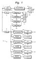
- Fig. 1 is a block diagram showing the structure of a motion determining apparatus according to an embodiment of the present invention.
- an input digital picture signal is received from an input terminal 1 and supplied to a tap forming circuit 2.
- the input digital picture signal is an interlace signal.
- the tap forming circuit 2 selects 50 pixels shown in Fig. 2 as taps used for the motion determining process and outputs the selected taps.
- Fig. 2 shows pictures of the same spatial position of three fields at chronologically successive times t-1, t, and t+1. Dots in Fig. 2 represent pixels sampled at a predetermined frequency. For example, one pixel represents an eight-bit luminance value.
- a position denoted by X represents a considered point. With respect to the considered point, the motion determining process is performed.
- the tap forming circuit 2 is connected to a telop motion detecting portion 3, a frame difference FrG detecting circuit 4, and a space slope SGsum detecting circuit 5.
- a selecting circuit 6 is connected to the telop motion detecting portion 3.
- Comparing devices 7, 8, and 9 are connected to the frame difference FrG detecting circuit 4.
- the comparing device 7 compares a frame difference FrG with a threshold value th2.
- the comparing device 8 compares the frame difference FrG with a threshold value th3.
- the comparing device 9 compares the frame difference FrG with a threshold value th4.
- a comparing device 10 is connected to the space slope SGsum detecting circuit 5.
- the comparing device 10 compares the space slope SGsum with a threshold value thl.
- the comparing device 7 When the input value (FrG) of the comparing device 7 is larger than the threshold value (th2), the comparing device 7 outputs "1". Otherwise, the comparing device 7 outputs "0".
- the comparing device 8 When the input value (FrG) of the comparing device 8 is larger than the threshold value (th3), the comparing device 8 outputs "1". Otherwise, the comparing device 8 outputs "0".
- the comparing device 9 outputs "1". Otherwise, the comparing device 9 outputs "0".
- the comparing device 10 When the input value (SGsum) of the comparing device 10 is larger than the threshold value (thl), the comparing device 10 outputs "1". Otherwise, the comparing device 10 outputs "0".
- a threshold value generating portion 12 is connected to the space slope SGsum detecting circuit 5. The relation of the threshold values is th2 > th3 > th4. The operation of the threshold value generating portion 12 will be described later.
- the frame difference FrG is obtained by calculating the differences between the pixel values of 15 taps of the field at time t-1 and the pixel values of 15 taps of the field at time t+1 (the spatial positions of the 15 taps of the field at time t-1 are the same as the spatial positions of the 15 taps of the field at time t+1), converting the obtained 15 frame difference values into the absolute values, and adding the absolute values.
- the amount of the motion between adjacent frames is proportional to the frame difference FrG.
- the space slope SGsum is the sum of the space slope SG(t-1) of the field at time t-1, the space slope SG(t) of the field at time t, and the space slope SG(t+1) of the field at time t+1. These space slopes are apace activities.
- the space slope of each field is obtained by calculating the difference values between pixels of adjacent fields and adding the absolute values of the difference values. In the case of a particular pixel at the upper left corder of the field at time t-1, the pixel immediately below the particular pixel and the pixel on the right of the particular pixel are adjacent pixels. The difference between the pixel value of the particular pixel and the pixel value of each of the adjacent pixels is calculated.
- the difference between the pixel value of a particular pixel and each of vertical and horizontal adjacent pixels is calculated.
- the space slope SG(t-1) of the field at time t-1 is obtained.
- the slope SG(t) of the field at time t and the slope SG(t+1) of the field at time t+1 are obtained.
- the compared results of the comparing devices 7, 8, and 9 are supplied to a motion class determining portion 11.
- the motion class determining portion 11 receives the compared results of the comparing devices 7, 8, 9, and 10 and generates a motion class MJ that is for example a three-bit code.
- the value of the motion class MJ is one of 0, 1, 2, and 3.
- the motion class MJ determining portion 11 determines the motion class MJ corresponding to the following conditions and supplies the determined motion class MJ to the selecting circuit 6.
- a region determining circuit 21, a region position determining circuit 22, a memory 23, and a th2 calculating circuit 24 are disposed.
- the space slope SGsum is supplied to the region determining circuit 21 and the region position determining circuit 22.
- the memory 23 outputs a parameter corresponding to output data of the region determining circuit 21.
- the th2 calculating circuit 24 receives output data of the region position determining circuit 22 and the parameter that is output from the memory 23 and generates the threshold value th2.
- four regions are defined by values represented by A0, A1, A2, and A3 of the space slope SGsum.
- the three regions (A0-A1), (A1-A2), and (A2-A3) have the same width.
- the threshold values th2, th3, and th4 are saturated.
- the region determining circuit 21 determines one of the four regions.
- threshold value levels B10, B11, B12, and B13 are defined corresponding to the values A0, A1, A2, and A3 of the space slope SGsum, respectively. These levels are output from the memory 23. In the region (A0-A1), the levels B10 and B11 are output from the memory 23 to the threshold value calculating circuit 24. Each of the three regions is equally divided by for example 64.
- the region position determining circuit 22 determines a position in a region. When the region position determining circuit 22 has determined a position in a region, the threshold value calculating circuit 24 performs linear compensating process and generates the threshold value th2. For example, at a position in the region (A0-A1), a coefficient corresponding to the position is multiplied by the levels B10 and B11 and the multiplied results are added. Thus, the threshold value th2 is obtained.
- a region determining circuit 31 To generate the threshold value th3, a region determining circuit 31, a region positon determining circuit 32, a memory 33, and a calculating circuit 34 are disposed.
- a region determining circuit 41 To generate the threshold value th4, a region determining circuit 41, a region position determining circuit 42, a memory 43, and a calculating circuit 44 are disposed.
- These structures operate in the same manner as the structure for generating the threshold value th2.
- the memory 34 stores levels B20, B21, B22, and B23 of the threshold value th3.
- the memory 44 stores levels B30, B31, B32, and B33 of the threshold value th4.
- the determined motion class MJ is supplied to the selecting circuit 6.
- the selecting circuit 6 selects the telop determined data received from the telop motion detecting portion 3 or the motion class MJ received from the motion class determining portion 11.
- the selecting circuit 6 supplies the selected data to an output terminal 13. For example, one class (mono class) is assigned to the telop determined data. When condition A or B is satisfied, the telop determined data represents that there is a motion of a telop portion.
- the selecting circuit 6 When the telop determined data represents that there is a motion of a telop portion, the selecting circuit 6 outputs the telop determined data with high priority. When the telop determined data represents that there is no motion of a telop portion, the selecting circuit 6 outputs the motion class MJ.
- the motion class determining portion 11 may be connected to a majority determining portion so as to determine the final motion class corresponding to the rule of majority. By the majority determining process, isolated points of motion classes can be removed. Thus, the conformation of motion classes in spatially adjacent regions can be improved.
- the telop determined data may be treated as a part of motion classes rather than a mono class.
- classes are determined corresponding to the following conditions.
- the telop determined data represents that there is a motion of a telop portion.
- the telop determined data represents that there is no motion of a telop portion.
- a telop is a sequence of characters and/or symbols superimposed with a picture.
- the present invention can be applied for a detecting process for pictures of video games, computer graphics, and so forth as well as the above-described telop.
- these pictures have common characteristics as picture signals of which pixels with constant luminance are chronologically and spatially successive and that represent characters, symbols, and/or graphics.
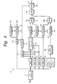
- Fig. 4 shows an example of the structure of the telop motion detecting portion 3.
- the tap forming circuit 2 is connected to detecting circuits 51, 52, and 53, a frame difference FrG detecting circuit 54, a field difference detecting circuit 55, and a dynamic range DR detecting circuit 56.
- the detecting circuits 51, 52, and 53 detect space slopes SG(t), SG(t-1), and SG(t+1), respectively.
- the space slopes SG(t), SG(t-1), and SG(t+1) are space slopes of fiels at times t-1, t, and t+1 that are chronologically successive, respectively.
- Sgsum SG(t-1) + SG(t) + SG(t+1)
- the frame difference FrG is the same as that used in the motion class detecting process.
- the detecting circuits 51, 52, 53, and 54 shown in Fig. 4 can be used in common with the detecting circuits 4 and 5 shown in Fig. 1.
- the dynamic range DR is the difference between the maximum value and the minimum value of taps (50 pixels) and represents a space activity.
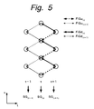
- Fig. 5 is a schematic diagram for explaining the field difference. Between successive fields, in the interlace system, vertical line positions deviate. Thus, there are two types of differences. One type is a difference between a current line and an upper line of another field (this difference is represented by a suffix u). The other type is a difference between a current line and a lower line of another field (this difference is represented by a suffix d).
- FiGut-1 represents an upward field difference between the field at time t-1 and the field at time t.
- FiGdt-1 represents a downward field difference between the field at time t-1 and the field at time t.
- FiGut represents an upward field difference between the field at time t and the field at time t+1.
- FiGdt represents a downward field difference between the field at time t and the field at time t+1.
- the frame difference FrG the sum of the absolute values of the differences of the pixels of a block of (5 x 3 pixels) and a block of (5 x 4 pixels) (see Fig. 2) is detected as a field difference.
- the field difference detecting circuit 55 detects these four field differences.
- the field difference detecting circuit 55 detects wether or not there is a motion of a telop portion corresponding to the following determination conditions. When condition A or B is satisfied, the field difference detecting circuit 55 determines that there is a motion of a telop portion. Otherwise, the field difference detection circuit 55 determines that there is no motion of a telop portion.
- the space slopes SG(t), SG(t-1), and SG(t+1) are supplied to a minimum value detecting portion 59.
- the minimum value detecting portion 59 detects the minimum space slope and supplies it to a comparing device 60.
- the comparing device 60 compares the minimum space slope with a threshold value th6.
- the comparing device 60 supplies the compared result to an AND circuit 61.
- the frame difference FrG detected by the detecting circuit 54 is supplied to a comparing device 62.
- the comparing device 62 compares the frame difference FrG with a threshold value th7.
- the comparing device 62 supplies the compared result to the AND circuit 61.
- the dynamic range DR detected by the detecting circuit 56 is supplied to a comparing device 63.
- the comparing device 63 compares the dynamic range DR with a threshold value th8.
- the comparing device 63 supplies the compared result (DR1) to the AND circuit 61.
- All the comparing devices that include those that will be described later output 1 as the compared results when input data is larger than the respective threshold value.
- the AND circuit 61 outputs "1".
- Output data of the AND circuit 61 is supplied to the AND circuit 65 through an OR circuit 64.
- the compared result of the comparing device 58 is supplied to the AND circuit 65.
- the AND circuit 65 outputs "1".
- the output data of the AND circuit 65 is "1" it represents that condition A is satisfied and that there is a motion of a telop portion.
- the output data of the AND circuit 65 is "0" it represents that there is no motion of a telop portion.
- the field differences detected by the detecting circuit 55 are supplied to a maximum value detecting portion 66.
- the maximum value detecting portion 66 detects the maximum value of the four field differences and supplies the maximum field difference to a comparing device 67.
- the comparing device 67 compares the maximum field difference with a threshold value th9.
- the comparing device 67 supplies the compared result to an AND circuit 68.
- the frame difference FrG detected by the detecting circuit 54 is supplied to a comparing device 69.
- the comparing device 69 compares the frame difference FrG with a threshold value thlO.
- the comparing device 69 supplies the compared result to the AND circuit 68.
- the dynamic range DR detected by the detecting circuit 56 is supplied to a comparing device 70.
- the comparing device 70 compares the dynamic range DR with a threshold value 11.
- the comparing device 70 supplies the compared result (DR2) to the AND circuit 68.
- the AND circuit 68 When the compared results of the comparing devices 67, 69, and 70 are all "1", the AND circuit 68 outputs "1". Output data of the AND circuit 68 is supplied to the AND circuit 65 through the OR circuit 64. The compared result of the comparing device 58 is supplied to the AND circuit 65. Thus, when the output data of the AND circuit 68 is "1" and the compared result of the comparing device 58 is “1", the AND circuit 65 outputs "1". When the output data of the AND circuit 65 is "1", it represents that condition B is satisfied and that there is a motion of a telop portion. When the output data of the AND circuit 65 is "0", it represents that there is no motion of a telop portion.
- Data that represents whether or not there is a motion of a telop portion is supplied from the telop motion detecting portion 2 to the selecting circuit 6 (see Fig. 1).
- the selecting circuit 6 selects "1".
- the selecting circuit 6 selects a motion class.
- values 0 to 3 of the motion class are represented by three bits
- a telop class that represents that there is a motion of a telop portion is assigned three bits that are different from the motion class.
- the selecting circuit 6 generates the three-bit code corresponding to the output data of the telop motion detecting portion 2.
- the tap forming circuit 2 is connected to a detecting circuit 71, a detecting circuit 72, a vertical filter 73, and a detecting circuit 74.
- the detecting circuit 71 detects the sum SGsum of space slopes SG(t), SG(t-1), and SG(t+1).
- the detecting circuit 72 detects a frame difference FrG.
- the detecting circuit 74 detects a dynamic range DR. The sum SGsum satisfies the following relation.
- An output signal of the filter 73 is supplied to a subtracting device 75.
- An output signal of the tap forming circuit 2 is also supplied to the subtracting device 75.
- the subtracting device 75 calculates the difference between a field that has been vertically filtered by the vertical filter 73 and another field.
- a field difference generating circuit 76 generates a field difference FiG1(t).
- a field difference generating circuit 77 generates a field difference FiG2 (t) .
- Fig. 7 is a schematic diagram for explaining a field difference.
- the subtracting device 75 generates the difference between a pixel of the field at time t-1 and an interpolated value of the field at time t that is output from the filter 73 (this difference is referred to as first difference) and the difference between a pixel of the field at time t+1 and an interpolated value of the field at time t that is output from the filter 73 (this difference is referred to as second difference).
- the field difference generating circuit 76 converts the first difference into the absolute value thereof. In reality, the field difference generating circuit 76 cumulates the absolute values of 15 first differences per block and generates the field difference FiG1(t). Likewise, the field difference generating circuit 77 generates the field difference FiG2(t) that is the sum of the absolute values of 15 second differences per block. With the detected field differences, it is determined whether or not there is a motion of a telop portion corresponding to the following determination conditions. When condition A or B is satisfied, it is determined that there is a motion of a telop portion. Otherwise, it is determined that there is no motion of a telop portion. The vertical filtering process may be performed for the field at time t-1 and the field at time t+1.
- the field difference FiGl(t) generated by the field difference generating circuit 76 is supplied to a comparing device 79.
- the comparing device 79 compares the field difference FiGl(t) with a threshold value th13.
- the comparing device 79 supplies the compared result to an AND circuit 82.
- the frame difference FrG detected by the detecting circuit 72 is supplied to a comparing device 80.
- the comparing device 80 compares the frame difference FrG with a threshold value th14.
- the comparing device 80 supplies the compared result to the AND circuit 82.
- the dynamic range DR detected by the detecting circuit 74 is supplied to a comparing device 81.
- the comparing device 81 comprares the dynamic range DR with a threshold value th15.
- the comparing device 81 supplies the compared result (DR1) to the AND circuit 82.
- the AND circuit 82 When the compared results of the comparing devices 79, 80, and 81 are all "1", the AND circuit 82 outputs "1".
- the output data of the AND circuit 82 is supplied to the AND circuit 84 through an OR circuit 83.
- the compared result of the comparing device 78 is supplied to the AND circuit 84.
- the AND circuit 84 When the output data of the AND circuit 84 is "1" and the compared result of the comparing device 78 is "1", the AND circuit 84 outputs "1".
- the output data of the AND circuit 84 When the output data of the AND circuit 84 is "1", it represents that condition A is satisfied and that there is a motion of a telop portion.
- the output data of the AND circuit 84 When the output data of the AND circuit 84 is "0", it represents that there is no motion of a telop portion.
- the field difference FiG2(t) generated by the field difference generating circuit 77 is supplied to a comparing device 85.
- the comparing device 85 compares the field difference FiG2(t) with a threshold value th16.
- the comparing device 85 supplies the compared result to an AND circuit 86.
- the frame difference FrG detected by the detecting circuit 72 is supplied to a comparing device 87.
- the comparing device 87 compares the frame difference FrG with a threshold value th17.
- the comparing device 87 supplies the compared result to the AND circuit 86.
- the dynamic range DR detected by the detecting circuit 74 is supplied to a comparing device 88.
- the comparing device 88 compares the dynamic range DR with a threshold value th18.
- the comparing device 88 supplies the compared result (DR2) to the AND circuit 86.
- the AND circuit 86 When the compared results of the comparing devices 85, 87, and 88 are all "1", the AND circuit 86 outputs "1".
- the output data of the AND circuit 86 is supplied to the AND circuit 84 through the OR circuit 83.
- the compared result of the comparing device 78 is supplied to the AND circuit 84.
- the AND circuit 84 When the output data of the AND circuit 86 is "1" and the compared result of the comparing device 78 is "1", the AND circuit 84 outputs "1".
- the output data of the AND circuit 84 When the output data of the AND circuit 84 is "1", it represents that condition B is satisfied and that there is a motion of a telop portion.
- the output data of the AND circuit 84 When the output data of the AND circuit 84 is "0", it represents that there is no motion of a telop portion.
- the data that represents whether or not there is a motion of a telop portion is supplied from the telop motion detecting portion 2 shown in Fig. 6 to the selecting circuit 6 shown in Fig. 1.
- the selecting circuit 6 selects "1".
- the selecting circuit 6 selects a motion class.
- the dynamic range DR is used as a space activity.
- One telop detection condition is that the dynamic range DR is equal to or larger than a predetermined threshold value.
- a space activity detected by the structure shown in Fig. 8 may be used.
- pixel values of a plurality of taps (50 taps shown in Fig. 2) connected to a tap forming circuit 91 are supplied to a maximum value detecting circuit 92 and a minimum value detecting circuit 93.
- the detected maximum value and minimum value are supplied to comparing devices 94 and 95, respectively.
- the comparing device 94 compares the maximum value with a threshold value th19.
- the comparing device 95 compares the minimum value with a threshold value th20. When the maximum value is equal to or larger than the threshold value th19, the comparing device 94 generates "1". When the minimum value is equal to or larger than the threshold value th20, the comparing device 95 output "1".
- the comparing devices 94 and 95 supply the respective compared results to an AND circuit 96.
- the AND circuit 96 generates output data.
- the output data of the AND circuit 96 represents that the maximum value is equal to or larger than the threshold values th19 and the minimum value is equal to or larger than the threshold value th20. Instead of the output data that represents that the dynamic range DR is equal to or larger than a predetermined threshold value, the output data of the AND circuit 96 may be used.
- the motion determining apparatus can be applied for a motion class generating process of a picture signal converting apparatus.
- the picture signal converting apparatus inputs an SD (Standard Definition) signal and outputs an HD (High Definition) signal.
- SD Standard Definition
- HD High Definition
- a predictive coefficient value is obtained. In such a manner, HD pixels more closer to real values can be obtained.
- Fig. 9 shows the structure of the picture signal converting apparatus that performs such a method.
- an input SD signal (525i signal) is supplied to a first tap selecting circuit 101, a second tap selecting circuit 103, and a third tap selecting circuit 104.
- the first tap selecting circuit 101 selects SD pixels that are used for predicting HD pixels (the SD pixels are referred to as predictive taps) .
- the second tap selecting circuit 103 selects SD pixels used to categorize classes corresponding to a distribution pattern of levels of SD pixels present in the vicinity of HD pixels to be generated (hereinafter, the SD pixels are referred to as spatial class taps).
- the third tap selecting circuit 104 selects SD pixels used to categorize classes of motion corresponding to SD pixels present in the vicinity of HD pixels to be generated (hereinafter the SD pixels are referred to as motion class taps).
- Predictive taps selected by the first tap selecting circuit 101 are supplied to an estimation predictive calculating circuit 102.
- Spatial class taps selected by the second tap selecting circuit 103 are supplied to a spatial class detecting circuit 105.
- the spatial class detecting circuit 105 detects a spatial class.
- the detected spatial class is supplied to a class combining circuit 107.
- Motion class taps selected by the third tap selecting circuit 104 are supplied to a motion class detecting circuit 106.
- the motion class detecting circuit 106 detects a motion class.
- the detected motion class is supplied to a class combining circuit 107.
- the class combining circuit 107 combines the spatial class and the motion class and generates a final class code.
- the class code is supplied as an address to a coefficient memory 108.
- Coefficient data corresponding to the class code is read from the coefficient memory 108.
- the coefficient data and the predictive taps are supplied to the estimation predictive calculating circuit 102.
- the estimation predictive calculating circuit 102 calculates data of an output picture signal (525p signal) corresponding to a linear estimation expression of the predictive taps (pixels of the 525i signal) and the predictive coefficients.
- the estimation predictive calculating circuit 102 outputs data of the current line (this data is referred to as line data L1) and data of a line to be generated (this data is referred to as line data L2).
- the estimation predictive calculating circuit 102 outputs pixels in the vertical direction twice as many as those in the horizontal direction.
- the 525i signal represents an interlace signal with 525 scanning lines.
- the 525p signal represents a progressive signal (non-interlace signal) with 525 scanning lines.
- the line data L1 and L2 received from the estimation predictive calculating circuit 102 are supplied to a line sequential converting circuit 109.
- the line sequential converting circuit 109 performs a line double speed process. Since the estimation predictive calculating circuit 102 generates the 525p signal with the 525i signal, the horizontal period of the 525p signal is the same as the horizontal period of the 525i signal.
- the line sequential converting circuit 109 performs a line double speed process for doubling the horizontal interval.
- the line sequential converting circuit 109 outputs the 525p signal.
- Fig. 10 is an enlarged view of a part of a picture of one field.
- Fig. 10 shows an arrangement of pixels of a 525i signal and a 525p signal.
- large dots represent pixels of the 525i signal, whereas small dots represent pixels of the 525p signal.
- Fig. 10 shows an arrangement of pixels of an odd field (o) of a particular frame (F).
- lines of the 525i signal spatially deviate by 0.5 lines each.
- line data L1 at the same position of each line of the 525i signal and line data L2 at the center position of the upper and lower lines thereof are generated.
- the number of pixels of each line in the horizontal direction is twice as many as that in the vertical direction. Consequently, the estimation predictive calculating circuit 102 generates data of four pixels of the 525p signal at a time.
- Fig. 11 shows analog waveforms in the line double speed process.
- the estimation predictive calculating circuit 102 generates line data L1 and L2.
- the line data L1 contains lines a1, a2, a3, and so forth arranged in the order.
- the line data L2 contains lines b1, b2, b3, and so forth contained in the order.
- the line sequential converting circuit 109 compresses data of each line in the time axis direction by 1/2.
- the line sequential converting circuit 109 alternately selects the compressed data of each line and generates line sequential data (a0, b0, a1, b1, and so forth).
- the output picture signal is supplied to a CRT displaying unit (not shown).
- the CRT displaying unit has a synchronizing system corresponding to the output picture signal (525p signal).
- the input picture signal is a broadcast signal or a reproduction signal of a reproducing unit such as a VCR.
- the apparatus according to the embodiment of the present invention can be built in a television receiver.
- Fig. 12 shows taps (SD pixels) selected by the second tap selecting circuit 103.
- Fig. 12 shows an arrangement of pixels in the vertical direction of an odd field of a frame F-1 (this field is denoted by F-1/o), an even field thereof (this field is denoted by F-1/e), an odd field of a frame F (this field is denoted by F/o), and an even field thereof (this field is denoted by F/e) that are chronologically sequential.
- spatial class taps for predicting line data L1 and line data L2 of the field F/o are input pixels T1 and T2, input pixels T3, T4, and T5, and input pixels T6 and T7.
- the input pixels T1 and T2 are contained in the field F/e and present spatially in the vicinity of pixels of the 525p signal to be generated.
- the input pixels T3, T4, and T5 are contained in the field F/o and present in the vicinity of pixels of the 525p signal to be generated.
- the input pixels T6 and T7 are contained in the field F-1/e.
- taps are selected. In mode 1 for predicting pixels of the line data L1, the pixel T7 may not be selected as a class tap. In mode 2 for predicting pixels of the line data L2, the pixel T4 may not be selected as a class tap.
- the motion determining apparatus is applied for the motion class detecting circuit 106.
- taps selected by the tap selecting circuit 104 namely, motion class taps
- the telop class or motion class MJ is determined.
- the determined class is supplied as a motion class to the class combining circuit 107.
- a class that represents that there is a motion of a telop portion is designated.
- a class that represents that there is a motion of a telop portion is designated as one of a plurality of classes that represent the amount of the motion of the telop portion.
- Spatial class taps selected by the tap selecting circuit 103 are supplied to the spatial class detecting circuit 105.
- the spatial class detecting circuit 105 detects a pattern of a level distribution of the selected spatial class taps.
- the spatial class detecting circuit 105 compresses eight-bit SD data of each pixel to two-bit SD data.
- the spatial class detecting circuit 105 compresses data of SD pixels as spatial class taps corresponding to ADRC (Adaptive Dynamic Range Coding) method.
- ADRC Adaptive Dynamic Range Coding
- another compressing means such as DPCM (predictive encoding method) or VQ (vector quantizing method) may be used instead of the ADRC method.
- the ADRC method is an adaptively requantizing method developed for a high efficient encoding process for use with a VCR (Video Cassette Recorder). Since the ADRC method allows a local pattern of a signal level to be effectively represented with a short word length, according to the embodiment of the present invention, the ADRC method is used to generate a spatial class categorization code. In the ADRC method, the length between the maximum value MAX and the minimum value MIN is equally divided by a designated bit length and re-quantized corresponding to the following formula (1).
- DR MAX - MIN + 1
- Q ⁇ (L - MIN + 0.5) x 2/DR ⁇
- DR represents the dynamic range of spatial class taps
- L represents the data level of the pixel of each spacial class tap
- Q represents a re-quantized code
- ⁇ ⁇ represents a truncating process
- the obtained predictive coefficient for each class is stored to the predictive coefficient memory 108.
- the predictive coefficient is information for converting the 525i signal into the 525p signal corresponding to a linear estimation expression. The method for obtaining the predictive coefficient will be described later.
- a predictive coefficient corresponding to a class is read from a relevant address of the coefficient memory 108.
- the predictive coefficient is supplied to the estimation predictive calculating circuit 102.
- the estimation predictive calculating circuit 102 calculates a liner combination expression (formula (2)) with predictive taps (pixel values) T1, T2 ..., and Ti received from the tap selecting circuit 101 and predictive coefficients w1, w2, ..., and wi and obtains line data L1 and L2. It should be noted that the predictive coefficient of the line data L1 is different from the predictive coefficient of the line data L2.
- L1 w1T1 + w2T2 + ... + wiTi
- a predictive coefficient is pre-learnt for each class and stored to the predictive coefficient memory 108.
- output data corresponding to input data is calculated and output.
- an SD picture corresponding to a known HD picture (a 525p signal) is generated by a two-dimensional thin-out filter 120 (in this case, the number of pixels of the SD picture is 1/4 that of the HD picture).
- a vertical thin-out filter For example, pixels in the vertical direction of HD data are thinned out by a vertical thin-out filter so that the frequency in the vertical direction of the field is halved.
- pixels in the horizontal direction of HD data are thinned out by a horizontal thin-out filter.
- An SD signal that is output from the two-dimensional thin-out filter 120 is supplied to a tap selecting circuit 121, a tap selecting circuit 122, and a tap selecting circuit 123.
- the tap selecting circuits 121, 122, and 123 select predictive taps, spatial class taps, and motion taps, respectively.
- the predictive taps are supplied from the tap selecting circuit 121 to a normal equation adding circuit 127.
- the spatial class taps are supplied from the tap selecting circuit 122 to a spatial class detecting circuit 124.
- the motion class taps are supplied from the tap selecting circuit 123 to a motion class detecting circuit 125.
- the spatial class detecting circuit 124 compresses data of the spatial class taps corresponding to the ADRC method and generates a spatial class code.
- the motion class detecting circuit 125 generates a motion class code with the motion class taps.
- a class combining circuit 126 combines the spatial class code and the motion class code and generates a final class code. The final class code is supplied from the class combining circuit 126 to the normal equation adding circuit 127.
- a process for learning a conversion expression for converting a plurality of SD pixels into one HD pixel and a signal converting process using a prediction expression thereof will be described.
- a predicting process using n pixels will be described.
- a liner estimation expression with n taps of coeficient data w1, ..., and wn for each class is given by the formula (3).
- wi is an undefined coefficient.
- y w1 x 1 + w2 x 2 + ... + wn x n where x1, x2, ... , and xn represent levels of SD pixels selected as predictive taps; and y represents the level of an HD pixel.
- a plurality of signals of data are learnt for each class.
- the number of pieces of data is m
- the following formula (4) is given corresponding to the formula (3).
- the formula (10) is generally referred to as normal equation.
- the normal equation adding circuit 127 shown in Fig. 13 performs the addition of the normal equation with class information received from the class combining circuit 126, predictive taps received from the tap selecting circuit 121, and pixels (a teacher signal) of a progressive picture to be generated.
- the normal equation adding circuit 127 outputs normal equation data to the predictive coefficient determining portion 128.
- the predictive coefficient determining portion 128 solves the normal equation data with respect to wi using a conventional matrix solution such as sweep-out method and obtains predictive coefficients.
- the predictive coefficient determining portion 128 writes the obtained predictive coefficients to a predictive coefficient memory 129.
- predictive coefficients that allow values that are the statistically closest to the real value of the considered pixel Y of the progressive picture to be predicted for individual classes are stored to the predictive coefficient memory 129.
- the predictive coefficients stored in the predictive coefficient memory 129 are loaded to the predictive coefficient memory 108 of the picture signal converting apparatus.
- the present invention can be applied for an output picture signal with another scanning line structure.
- the present invention can be applied to a signal converting process for converting a 525i signal into a 1050i signal (a 1050-line interlace signal).
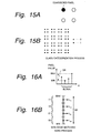
- a block of (2 x 2 pixels) (this block is referred to as class categorization block) is formed.
- each pixel is represented by one bit ("0" or "1").
- Such a pattern categorizing process is performed as a class categorizing process by the class categorizing circuit 45.
- the class categorizing process may be performed in consideration of an activity (that represents the complexity) of a picture (of the block).
- each pixel is assigned for example eight bits.
- a class categorization block is composed of nine (3 x 3) pixels with a considered pixel present at the center thereof.
- a huge number of classes of (2 8 ) 9 are obtained.
- the ADRC process is performed for a class categorization block. Consequently, the number of bits of each pixel composing the class categorization block (thus, the number of classes) is reduced.
- a block composed of four pixels arranged on a straight line is considered.
- the maximum value and the minimum value of the pixel values of the four pixels are detected.
- the pixel value of each pixel composing the block is re-quantized to K bits.
- the minimum value MIN is subtracted from each pixel value of the block.
- the resultant value is divided by DR/2 k .
- the resultant value is converted into an ADRC code.
- K 2 2 .
- it is determined whether or not the resultant value is categorized as any region of which the dynamic range DR is divided by 4 ( 2 2 ).
- a two-bit code 00B, 01B, 10B, or 11B is assigned (where B represents a binary notation).
- the ADRC code 00B, 01B, 10B, or 11B is converted into L 00 , L 01 , L 10 , or L 11 , respectively (where L 00 is the center value of the lowest level, L 01 is the center value of the second lowest level, L 10 is the center value of the third lowest level, and L 11 is the center value of the highest level).
- L 00 is the center value of the lowest level
- L 01 is the center value of the second lowest level
- L 10 is the center value of the third lowest level
- L 11 is the center value of the highest level
- Such an ADRC process is referred to as non-edge matching process.
- the number of classes can be reduced.
Landscapes
- Engineering & Computer Science (AREA)
- Multimedia (AREA)
- Signal Processing (AREA)
- Computer Vision & Pattern Recognition (AREA)
- Physics & Mathematics (AREA)
- General Physics & Mathematics (AREA)
- Theoretical Computer Science (AREA)
- Television Systems (AREA)
- Compression Or Coding Systems Of Tv Signals (AREA)
- Image Analysis (AREA)
Applications Claiming Priority (2)
| Application Number | Priority Date | Filing Date | Title |
|---|---|---|---|
| JP24944898 | 1998-09-03 | ||
| JP24944898A JP4168490B2 (ja) | 1998-09-03 | 1998-09-03 | 動き判定装置、その方法および画像情報変換装置 |
Publications (2)
| Publication Number | Publication Date |
|---|---|
| EP0984624A2 true EP0984624A2 (fr) | 2000-03-08 |
| EP0984624A3 EP0984624A3 (fr) | 2001-09-05 |
Family
ID=17193128
Family Applications (1)
| Application Number | Title | Priority Date | Filing Date |
|---|---|---|---|
| EP19990306982 Withdrawn EP0984624A3 (fr) | 1998-09-03 | 1999-09-02 | Appareil et procédé permettant la détermination de mouvement et appareil pour la conversion de données d'images |
Country Status (4)
| Country | Link |
|---|---|
| US (1) | US6597737B1 (fr) |
| EP (1) | EP0984624A3 (fr) |
| JP (1) | JP4168490B2 (fr) |
| KR (1) | KR100652467B1 (fr) |
Cited By (3)
| Publication number | Priority date | Publication date | Assignee | Title |
|---|---|---|---|---|
| EP1313310A3 (fr) * | 2001-11-19 | 2004-08-11 | Matsushita Electric Industrial Co., Ltd. | Méthode de conversion entrelacé-progressif d'un format vidéo avec faible latence |
| US7362378B2 (en) | 2005-01-10 | 2008-04-22 | Matsushita Electric Industrial Co., Ltd. | Method of edge based pixel location and interpolation |
| CN101662583B (zh) * | 2008-08-29 | 2012-12-26 | 三星Techwin株式会社 | 数字照相设备、控制该数字照相设备的方法 |
Families Citing this family (7)
| Publication number | Priority date | Publication date | Assignee | Title |
|---|---|---|---|---|
| JP4691812B2 (ja) * | 2001-03-29 | 2011-06-01 | ソニー株式会社 | 係数データの生成装置および生成方法、それを使用した情報信号の処理装置および処理方法 |
| JP2003110659A (ja) * | 2001-09-28 | 2003-04-11 | Toshiba Corp | 移動通信端末 |
| JP4296935B2 (ja) * | 2002-02-21 | 2009-07-15 | ソニー株式会社 | 信号処理装置 |
| KR100517504B1 (ko) * | 2003-07-01 | 2005-09-28 | 삼성전자주식회사 | B-픽처의 움직임 보상 모드 결정방법 및 장치 |
| CN102946504B (zh) * | 2012-11-22 | 2015-02-18 | 四川虹微技术有限公司 | 一种基于边缘检测的自适应运动检测方法 |
| CN102946505B (zh) * | 2012-11-22 | 2015-02-18 | 四川虹微技术有限公司 | 一种基于图像分块统计的自适应运动检测方法 |
| CN111462190B (zh) * | 2020-04-20 | 2023-11-17 | 海信集团有限公司 | 一种智能冰箱及食材录入方法 |
Family Cites Families (23)
| Publication number | Priority date | Publication date | Assignee | Title |
|---|---|---|---|---|
| JP2634632B2 (ja) | 1988-06-15 | 1997-07-30 | 株式会社日立製作所 | 動き検出回路 |
| JP2830111B2 (ja) * | 1989-07-21 | 1998-12-02 | ソニー株式会社 | 高能率符号化装置 |
| US5539466A (en) * | 1991-07-30 | 1996-07-23 | Sony Corporation | Efficient coding apparatus for picture signal and decoding apparatus therefor |
| US5245436A (en) * | 1992-02-14 | 1993-09-14 | Intel Corporation | Method and apparatus for detecting fades in digital video sequences |
| US6226327B1 (en) * | 1992-06-29 | 2001-05-01 | Sony Corporation | Video coding method and apparatus which select between frame-based and field-based predictive modes |
| JP3036287B2 (ja) * | 1992-12-15 | 2000-04-24 | 富士ゼロックス株式会社 | 動画像シーン検出装置 |
| JP2591441B2 (ja) * | 1993-09-28 | 1997-03-19 | 日本電気株式会社 | 動画像信号の動ベクトル検出装置 |
| JP2823495B2 (ja) * | 1993-10-27 | 1998-11-11 | 三洋電機株式会社 | 動き検出回路及びテレビジョン受信機 |
| US5903481A (en) * | 1994-09-09 | 1999-05-11 | Sony Corporation | Integrated circuit for processing digital signal |
| US5563651A (en) * | 1994-12-30 | 1996-10-08 | Thomson Consumer Electronics, Inc. | Method and apparatus for identifying video fields produced by film sources employing 2-2 and 3-2 pull down sequences |
| US5508750A (en) * | 1995-02-03 | 1996-04-16 | Texas Instruments Incorporated | Encoding data converted from film format for progressive display |
| JPH08265770A (ja) * | 1995-03-20 | 1996-10-11 | Sony Corp | 高能率符号化方法、高能率符号化装置、記録再生装置及び情報伝送システム |
| JPH08317301A (ja) * | 1995-05-22 | 1996-11-29 | Hitachi Ltd | 映像出力装置 |
| US5946044A (en) | 1995-06-30 | 1999-08-31 | Sony Corporation | Image signal converting method and image signal converting apparatus |
| JP3669530B2 (ja) * | 1995-06-30 | 2005-07-06 | ソニー株式会社 | 画像信号変換装置及び画像信号変換方法 |
| JP3504439B2 (ja) | 1996-07-25 | 2004-03-08 | 日本電信電話株式会社 | 映像検索方法 |
| US6104755A (en) * | 1996-09-13 | 2000-08-15 | Texas Instruments Incorporated | Motion detection using field-difference measurements |
| JP3609236B2 (ja) | 1997-05-16 | 2005-01-12 | 日本電信電話株式会社 | 映像テロップ検出方法および装置 |
| JP3470938B2 (ja) | 1997-05-20 | 2003-11-25 | 日本電信電話株式会社 | テロップ文字表示フレーム検出方法及び装置 |
| US6084641A (en) * | 1997-08-06 | 2000-07-04 | General Instrument Corporation | Fade detector for digital video |
| JPH1169356A (ja) * | 1997-08-25 | 1999-03-09 | Mitsubishi Electric Corp | 動画像符号化方式及び動画像復号方式 |
| JPH11168691A (ja) | 1997-12-04 | 1999-06-22 | Nippon Telegr & Teleph Corp <Ntt> | 映像蓄積表示装置 |
| JP4193233B2 (ja) * | 1998-08-12 | 2008-12-10 | ソニー株式会社 | 動き判定装置、その方法および画像情報変換装置 |
-
1998
- 1998-09-03 JP JP24944898A patent/JP4168490B2/ja not_active Expired - Fee Related
-
1999
- 1999-09-01 US US09/387,994 patent/US6597737B1/en not_active Expired - Fee Related
- 1999-09-02 EP EP19990306982 patent/EP0984624A3/fr not_active Withdrawn
- 1999-09-02 KR KR19990037080A patent/KR100652467B1/ko not_active Expired - Fee Related
Non-Patent Citations (1)
| Title |
|---|
| None |
Cited By (4)
| Publication number | Priority date | Publication date | Assignee | Title |
|---|---|---|---|---|
| EP1313310A3 (fr) * | 2001-11-19 | 2004-08-11 | Matsushita Electric Industrial Co., Ltd. | Méthode de conversion entrelacé-progressif d'un format vidéo avec faible latence |
| US7423691B2 (en) | 2001-11-19 | 2008-09-09 | Matsushita Electric Industrial Co., Ltd. | Method of low latency interlace to progressive video format conversion |
| US7362378B2 (en) | 2005-01-10 | 2008-04-22 | Matsushita Electric Industrial Co., Ltd. | Method of edge based pixel location and interpolation |
| CN101662583B (zh) * | 2008-08-29 | 2012-12-26 | 三星Techwin株式会社 | 数字照相设备、控制该数字照相设备的方法 |
Also Published As
| Publication number | Publication date |
|---|---|
| EP0984624A3 (fr) | 2001-09-05 |
| JP4168490B2 (ja) | 2008-10-22 |
| JP2000078539A (ja) | 2000-03-14 |
| US6597737B1 (en) | 2003-07-22 |
| KR100652467B1 (ko) | 2006-12-01 |
| KR20000022865A (ko) | 2000-04-25 |
Similar Documents
| Publication | Publication Date | Title |
|---|---|---|
| US7113225B2 (en) | Information signal processing apparatus, picture information converting apparatus, and picture displaying apparatus | |
| KR100289592B1 (ko) | 디지털 영상 신호에 대한 계층 엔코딩 및 디코딩장치 | |
| US7688383B2 (en) | Information signal processor, method for processing information signal, image signal processor and image display apparatus using the same, coefficient seed data production device used in the same, method for producing coefficient seed data set and information-providing medium | |
| EP0989748B1 (fr) | Conversion de données d'images et processeur vidéo | |
| EP0843475B1 (fr) | Dispositif et procede de conversion d'informations d'images | |
| EP0984624A2 (fr) | Appareil et procédé permettant la détermination de mouvement et appareil pour la conversion de données d'images | |
| US6404924B1 (en) | Image processing apparatus and method | |
| US6201833B1 (en) | Motion determining apparatus, method thereof, and picture information converting apparatus | |
| US6646684B1 (en) | Image conversion device and method | |
| US6433828B1 (en) | Picture conversion using field-by-field vertical inversion dependent upon the type of picture signal to be outputted | |
| JP3723995B2 (ja) | 画像情報変換装置および方法 | |
| US6707502B1 (en) | Apparatus and method for converting a field frequency of a picture signal | |
| KR100982625B1 (ko) | 정보 신호의 처리 장치 및 처리 방법 | |
| JP3480015B2 (ja) | 画像データの生成装置および生成方法 | |
| JP4123587B2 (ja) | 画像情報処理装置および方法 | |
| JP3800638B2 (ja) | 画像情報変換装置および方法 | |
| JP4193236B2 (ja) | 画像情報変換装置、画像情報変換方法、およびテレビジョン受像機 | |
| JPWO2000067480A1 (ja) | 画像信号変換装置および方法 | |
| JP2000050213A (ja) | 画像情報変換装置、変換方法および画像表示装置 | |
| JPH07193790A (ja) | 画像情報変換装置 | |
| JPH0799635A (ja) | 画像情報変換装置 | |
| JPH07193791A (ja) | 画像情報変換装置 |
Legal Events
| Date | Code | Title | Description |
|---|---|---|---|
| PUAI | Public reference made under article 153(3) epc to a published international application that has entered the european phase |
Free format text: ORIGINAL CODE: 0009012 |
|
| AK | Designated contracting states |
Kind code of ref document: A2 Designated state(s): AT BE CH CY DE DK ES FI FR GB GR IE IT LI LU MC NL PT SE |
|
| AX | Request for extension of the european patent |
Free format text: AL;LT;LV;MK;RO;SI |
|
| PUAL | Search report despatched |
Free format text: ORIGINAL CODE: 0009013 |
|
| AK | Designated contracting states |
Kind code of ref document: A3 Designated state(s): AT BE CH CY DE DK ES FI FR GB GR IE IT LI LU MC NL PT SE |
|
| AX | Request for extension of the european patent |
Free format text: AL;LT;LV;MK;RO;SI |
|
| 17P | Request for examination filed |
Effective date: 20020219 |
|
| AKX | Designation fees paid |
Free format text: DE FR GB |
|
| R17P | Request for examination filed (corrected) |
Effective date: 20020219 |
|
| RBV | Designated contracting states (corrected) |
Designated state(s): DE FR GB |
|
| 17Q | First examination report despatched |
Effective date: 20060929 |
|
| GRAP | Despatch of communication of intention to grant a patent |
Free format text: ORIGINAL CODE: EPIDOSNIGR1 |
|
| STAA | Information on the status of an ep patent application or granted ep patent |
Free format text: STATUS: THE APPLICATION IS DEEMED TO BE WITHDRAWN |
|
| 18D | Application deemed to be withdrawn |
Effective date: 20130319 |