EP0984816B1 - Lufttransportierte vorrichtung zum abwerfen oder spritzen von flüssigen produkten - Google Patents
Lufttransportierte vorrichtung zum abwerfen oder spritzen von flüssigen produkten Download PDFInfo
- Publication number
- EP0984816B1 EP0984816B1 EP98925764A EP98925764A EP0984816B1 EP 0984816 B1 EP0984816 B1 EP 0984816B1 EP 98925764 A EP98925764 A EP 98925764A EP 98925764 A EP98925764 A EP 98925764A EP 0984816 B1 EP0984816 B1 EP 0984816B1
- Authority
- EP
- European Patent Office
- Prior art keywords
- air according
- nozzle
- tank
- device transportable
- section
- Prior art date
- Legal status (The legal status is an assumption and is not a legal conclusion. Google has not performed a legal analysis and makes no representation as to the accuracy of the status listed.)
- Expired - Lifetime
Links
- 239000012263 liquid product Substances 0.000 title claims abstract description 16
- 238000005507 spraying Methods 0.000 title claims abstract description 14
- XLYOFNOQVPJJNP-UHFFFAOYSA-N water Substances O XLYOFNOQVPJJNP-UHFFFAOYSA-N 0.000 claims abstract description 25
- 238000004804 winding Methods 0.000 claims abstract description 10
- 239000003337 fertilizer Substances 0.000 claims abstract description 4
- 239000002917 insecticide Substances 0.000 claims abstract description 3
- 230000003247 decreasing effect Effects 0.000 claims description 4
- 238000011144 upstream manufacturing Methods 0.000 claims description 4
- 230000006641 stabilisation Effects 0.000 claims description 3
- 238000006073 displacement reaction Methods 0.000 claims description 2
- 238000011105 stabilization Methods 0.000 claims description 2
- 239000007921 spray Substances 0.000 description 12
- 238000006243 chemical reaction Methods 0.000 description 4
- 230000005484 gravity Effects 0.000 description 4
- 239000007788 liquid Substances 0.000 description 4
- 239000000047 product Substances 0.000 description 3
- 230000015572 biosynthetic process Effects 0.000 description 2
- 230000000295 complement effect Effects 0.000 description 2
- 238000010276 construction Methods 0.000 description 2
- 239000006260 foam Substances 0.000 description 2
- 238000012423 maintenance Methods 0.000 description 2
- 238000004519 manufacturing process Methods 0.000 description 2
- 208000031968 Cadaver Diseases 0.000 description 1
- 241000238631 Hexapoda Species 0.000 description 1
- 239000000654 additive Substances 0.000 description 1
- 230000000996 additive effect Effects 0.000 description 1
- 230000008033 biological extinction Effects 0.000 description 1
- 230000000694 effects Effects 0.000 description 1
- 239000012530 fluid Substances 0.000 description 1
- 239000003517 fume Substances 0.000 description 1
- 230000009545 invasion Effects 0.000 description 1
- 230000033001 locomotion Effects 0.000 description 1
- 238000005259 measurement Methods 0.000 description 1
- 239000003595 mist Substances 0.000 description 1
- 230000000284 resting effect Effects 0.000 description 1
- 239000000725 suspension Substances 0.000 description 1
Images


Classifications
-
- A—HUMAN NECESSITIES
- A62—LIFE-SAVING; FIRE-FIGHTING
- A62C—FIRE-FIGHTING
- A62C3/00—Fire prevention, containment or extinguishing specially adapted for particular objects or places
- A62C3/02—Fire prevention, containment or extinguishing specially adapted for particular objects or places for area conflagrations, e.g. forest fires, subterranean fires
- A62C3/0228—Fire prevention, containment or extinguishing specially adapted for particular objects or places for area conflagrations, e.g. forest fires, subterranean fires with delivery of fire extinguishing material by air or aircraft
- A62C3/0242—Fire prevention, containment or extinguishing specially adapted for particular objects or places for area conflagrations, e.g. forest fires, subterranean fires with delivery of fire extinguishing material by air or aircraft by spraying extinguishants from the aircraft
-
- B—PERFORMING OPERATIONS; TRANSPORTING
- B64—AIRCRAFT; AVIATION; COSMONAUTICS
- B64D—EQUIPMENT FOR FITTING IN OR TO AIRCRAFT; FLIGHT SUITS; PARACHUTES; ARRANGEMENT OR MOUNTING OF POWER PLANTS OR PROPULSION TRANSMISSIONS IN AIRCRAFT
- B64D1/00—Dropping, ejecting, releasing or receiving articles, liquids, or the like, in flight
- B64D1/16—Dropping or releasing powdered, liquid, or gaseous matter, e.g. for fire-fighting
Definitions
- the present invention relates to an airborne drop device or spraying of liquid products (for example water, with or without added products appropriate to the interventions to be carried out).
- liquid products for example water, with or without added products appropriate to the interventions to be carried out.
- the technical field of the invention is that of the fight against fires, in particular of forests, the claimed device can also be implemented in other fields such as the spreading of fertilizers or products for the fight against various pollutions or against invasion insects.
- a firefighting device using an aircraft such as a helicopter, which includes a water tank, a pressurization and propulsion pump water from the tank in a flexible pipe which extends and is suspended under the helicopter over a length or height of several tens to several hundreds of meters; a spray nozzle is fitted to one end of the flexible pipeline and allows the production of main jets, jets complementary or secondary as well as directional directed jets differently to help position the nozzle hanging at the helicopter via the hose; the tank and the pump are arranged in the helicopter.
- the air transportable device described in this document requires a special arrangement of the helicopter to receive a tank and a pump ; in addition, its use poses flight stability problems for the helicopter as the tank is emptied, as well as during variations in the attitude of the helicopter than during takeoff or the landing of the craft equipped with the above-mentioned device and its pipeline flexible.
- helicopter-borne devices comprising a tank for a liquid product arranged so that it can be suspended from a helicopter, means for the evacuation of this liquid product under pressure and spray nozzles arranged below and almost in contact with said reservoir for pouring said liquid in the form of jets or foam, some of these devices comprising a support structure provided with skids ground support.
- a first objective of the invention is therefore to remedy the drawbacks or insufficient devices of the kind described and illustrated in the attached documents.
- the latter is preferably constituted by a flexible hose "crushable" of the kind automatically adopting a flat conformation when it is outside service, the axis of rotation of this winch being advantageously arranged below of the liquid product tank.
- the helicopter or other aircraft capable of evolve at a height putting it out of reach of heat and flames generated by the braziers, and above the fumes produced by them.
- Another object of the invention is to remedy this situation unsatisfactory.
- a preferred embodiment of the invention comprises a nozzle formed by a body in the distal part of which is housed a flared core in the direction of the exit of said body, this core flared and the internal wall of the body which surrounds it defining a passage duct of variable section including, from upstream to downstream, a section of section decreasing, a section of narrowed section and a section of increasing section.
- This characteristic arrangement promotes the formation of spray jets and improves the hydraulic performance of the nozzle by reducing its pressure losses and also to decrease the reaction forces resulting from jets produced by the nozzle.
- the device 1 includes a sealed tank 2 (whose capacity is, for example, of the order of 1,000 to 10,000 liters) suitable for containing water, if necessary with additive favoring the extinction of fire fires, or other products depending on the device applications (fertilizers, insecticides, various depollutants, etc.); this tank 2 is, for example, cylindrical and / or of revolution of vertical axis 2a.
- a sealed tank 2 (whose capacity is, for example, of the order of 1,000 to 10,000 liters) suitable for containing water, if necessary with additive favoring the extinction of fire fires, or other products depending on the device applications (fertilizers, insecticides, various depollutants, etc.); this tank 2 is, for example, cylindrical and / or of revolution of vertical axis 2a.
- the reservoir 2 communicates with a flexible pipe 3 connecting the orifice outlet 25 formed in the bottom of the tank 2, to a spray nozzle 5 disposed at the free end of the pipe 3; the second end 7 of the line 3 is connected via a fitting or rotating joint 23, to a fixed pipe 24 (rigid or flexible) for connection to the outlet orifice 25 of tank 2.
- This connection pipe 24 is fitted with a valve 21 preferably motorized, the operation of which can be controlled by a operator or helicopter pilot, using an electric cable 28 supply thereof, equipped with a connector 27a for connection to a additional connector (not shown) fitted to the helicopter receiving the airborne device.
- the flexible pipe 3 is constituted by a flexible hose of the kind automatically taking a flattened conformation when it is not in use (for example a flexible hose of the hose type firefighter).
- This pipe has, for example, a thickness of the order of 2.5 mm, and its internal diameter can be between 25 and 150 mm, preferably between 50 to 100 mm, this internal diameter being, for example, of the order of 65 mm.
- the length of this flexible pipe can vary depending on the applications of the airborne spraying device and the diameter of said pipe. This length can, for example, be between 50 and 150 meters.
- This flexible pipe ensures spraying by the effect of gravity (the device according to the invention does not have a pump or any other means of pressurization), using the pressure resulting from the height of the column water or other spreading liquid existing inside said pipe and the tank.
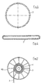
- Line 3 can be wound on a reel or winch winding 15 essentially consisting, in known manner, of a hub central cylindrical 4 equipped, at each of its ends, with a flange 18 in perforated disc shape, the pipe 3 being able to wrap around the hub central 4 and between said flanges 18 as shown particularly in the Figure 7 and Figure 2 illustrating said pipe 3 fully wound, in the state flattened, in several nested and / or coplanar turns, that is to say on a single thickness; consequently, the spacing between the flanges 18 is little greater than the width of the pipe 3 in the flattened state.
- the rotational movement of the reel 15 along its axis of rotation 17 substantially horizontal is effected by a drive motor 16 in rotation, which is preferably an electric motor connected to a source of electrical energy equipping the helicopter, via a cable 28 equipped with a suitable connector 27b; the reel 15 is fixed to the frame of the tank.
- a drive motor 16 in rotation which is preferably an electric motor connected to a source of electrical energy equipping the helicopter, via a cable 28 equipped with a suitable connector 27b; the reel 15 is fixed to the frame of the tank.
- the reel 15 is installed under the tank 2, at means of bearings 22 fixed to the lower horizontal elements 8a of the framework external 8 of the reservoir 1.
- the axis of rotation 17 of the reel 15 is arranged below the tank 2.
- the median plane of the reel coincides with one of the vertical median planes of the reservoir 2, while the axis of rotation 17 of said reel is arranged in the vertical median plane of the latter perpendicular to the previous one.
- the flight stability is further improved.
- the arrangement which has just been described allows a release or sprinkling of water or other liquid product, by gravity, with a spreading rate which can be between 100 and 1000 liters per minute, for example of the order of 400 to 600 liters per minute.
- a structure or framework 8 substantially in the form of a frame surrounding a part at less than tank 2; this structure is provided, at the bottom, with legs 10 (for example three or four) terminated by feet or skates 9 allowing the device to rest stably on the ground S as illustrated in Figure 2, when the device is waiting for use.
- legs 10 for example three or four
- feet 9 are connected by bars 9a improving the stability of the support of the device on the ground S.
- the frame-shaped structure 8 comprises, in the upper part, hooks 11 to which are attached slings 12 terminated by a suitable loop to be engaged in a hook 13a equipping a helicopter 13 or other aircraft, the hook 13a being substantially in the vertical extension of the center of gravity 14 of the helicopter and / or in the extension of the axis 26 of rotation of the main rotor thereof.
- the reservoir 2 is provided, in the central upper part, with an orifice 19 serving as a vent and allowing the introduction of air into the tank as and measurement of the emptying thereof.
- the free end of the flexible pipe 3 is provided with a spray nozzle 5 which could be of various known types in itself.
- the invention includes also an original nozzle, two embodiments of which are described below.
- This spray nozzle is first of all remarkable in that it comprises a body 30 in the distal part of which is housed coaxially a central core 38 flared towards the outlet of said body, this flared core 38 and the internal wall 31-34-35 of the body 30 which surrounds it delimiting a duct of passage of variable section including, from upstream to downstream, a section cylindrical 37, a section of decreasing section 42, a section of section narrowed 43 and a section of increasing section 44, this passage passage of variable section thus forming a nozzle and / or a venturi.
- the nozzle 5 is constituted by a body 30 delimited by a cylindrical external face of section for example constant and of longitudinal axis 36 for example common to the surface external of the body 30 and to its internal surface.
- the internal surface of the body 30 has a proximal end 32 threaded for connection of the nozzle to the flexible pipe (not shown) by the inlet port 33 of the nozzle.
- said internal surface also has a slightly convergent part 31 pursued by a portion of converging wall 34 itself pursued by a divergent inner wall portion 35; all of these walls 31, 34, 35 thus forming a nozzle or venturi with a longitudinal axis 36.
- a central core 38, preferably of revolution, of axis 36 merged with the longitudinal axis of the body 30, is housed coaxially in the distal part of said body, the outer walls 41 of this central core delimiting, with the different portions of the internal wall of the body 30, of the passage conduits (preferably axis revolution 36) which are successively identified 37, 42, 43, 44, and allow the guidance of the stream of fluid flowing in the nozzle of the orifice 33 inlet 39 outlet, and the production of jets 6 (directed to the ground) of optimally.
- the ratio of the section of the inlet orifice 33 to the section of the orifice of outlet 39 of nozzle 5, is for example between 2 and 4.
- the core 38 is fixed and maintained in position relative to the body 30 of the nozzle by three profiled fins 40 arranged radially at 120 degrees around the longitudinal axis 36 (or symmetry) of the nozzle.
- These mechanical connection fins reduce the obstacles present in the flow passage of the sprayed liquid and reduce, therefore, pressure losses, and also increase the available flow for a determined water height.
- FIGS 8 to 10 illustrate another advantageous embodiment and preferred of the spray nozzle according to the invention.
- the body 30 is connected to the distal end of the flexible pipe 3 (not shown) via a reducing cone 29 assembled at the proximal end of said body, for example by screwing.
- the internal wall of the body 30 and the lateral surface of the core 38 housed coaxially in said body delimit, as for the example of embodiment previously described, a passage section of variable section comprising, upstream towards the front, a cylindrical section 37, a section section decreasing 42, a narrowed section 43 and a section increasing 44.
- the central core 38 is fixed in the body 30 by means of a cap 45 comprising a lateral surface 46 and a bottom 47, this cap 45 covering the distal end of the body 30.
- the bottom 47 of the cap 45 is provided with slots arched 48 placed in correspondence with the outlet passage 44 of the body 30 and it is fixed to said body 30 by means of screws shown by the axis lines 49 of the figure 8.
- the central core 38 is fixed on the internal face of the bottom 47 of the cap 45 by means of an axial screw 50.
- the surfaces in contact with the central core 38 and the cap 45 include a central cylindrical post 47a, which for example has the bottom 47 of the cap 45, and a central cylindrical mortise 38a, of which is by example provided with the base of the central core 38, and into which can slide said tenon, so as to allow a slight axial displacement of said central core, by example of the order of 1 to 2 mm, using the screw 50.
- This arrangement allows to adjust the axial position of the central core 38 relative to the body 30, which allows to vary the flow and the shape of the jet.
- a piece of counter-jets 51 delimiting, around said proximal part, a chamber annular 52 communicating with the interior of the body 30, via a plurality of radial holes 53 (for example three or four in number) formed in the side wall of the latter.
- the proximal part of the piece of counter-jets 51 or external wall of the chamber 52 is provided with a plurality of channels 54 opening to the outside and oriented obliquely to the axis 36 of the nozzle, towards the end proximal to it, i.e. upwards considering the application very advantageous to airborne forest fire fighting systems or other fires.
- the counter-jet piece 51 is, for example, provided with three or four channels 54 of regularly spaced counter-jets oriented in a angle of the order of 10 ° relative to the axis 36 of the nozzle.
- the nozzle according to the invention allows water to be sprayed in the form of droplets, having the lowest possible reaction force for a flow rate important.
- the shapes of the core, the cylindrical body and the part of the counter-jets significantly reduce the reaction force of the spray of water.
- the nozzle maintains itself in a vertical position at the end a flexible pipe with a flow rate of 500 liters / minute.
- the internal functional surfaces S1, S2, S3 and S4 are of revolution and defined by specific equations.
- the surfaces S1 and S2 define the interior of the cylindrical body.
- the surfaces S3 and S4 define the core.
- the inlet diameter (corresponding to the outside diameter of the section of water passage), identical to the outlet diameter, can be between 10 and 150 millimeters, preferably around 45 millimeters.
- nozzle of different diameters (corresponding to the diameter outside of the water passage section), for example between 10 and 150 millimeters, is obtained by a homothety from equations of the nozzle of 45 millimeters.
- the interesting performances of the nozzle according to the invention allow to consider its use on other airborne spreading devices or spraying water or other liquid products, or even on equipment sprinkler working from the ground.
Landscapes
- Business, Economics & Management (AREA)
- Life Sciences & Earth Sciences (AREA)
- Ecology (AREA)
- Forests & Forestry (AREA)
- Health & Medical Sciences (AREA)
- Public Health (AREA)
- Engineering & Computer Science (AREA)
- Emergency Management (AREA)
- Biodiversity & Conservation Biology (AREA)
- Aviation & Aerospace Engineering (AREA)
- Catching Or Destruction (AREA)
- Nozzles (AREA)
- Fire-Extinguishing By Fire Departments, And Fire-Extinguishing Equipment And Control Thereof (AREA)
- Treatment Of Fiber Materials (AREA)
Claims (17)
- Lufttransportierte Vorrichtung zum Abwerfen oder Versprühen von Wasser oder einem anderen flüssigen Produkt, beispielsweise zum Bekämpfen von Bränden, Versprühen von Düngemitteln, Insektiziden oder Mitteln zur Beseitigung von Umweltverschmutzungen, umfassend:dadurch gekennzeichnet, daß sie einerseits eine biegsame Rohrleitung (3) umfaßt, deren erstes Ende mit einer Sprühdüse (5) verbunden ist und deren zweites Ende (7) mit dem Behälter (2) verbunden ist, und andererseits eine Aufrolleinrichtung oder Wickelhaspel (15) für die biegsame Rohrleitung (3).einen Behälter (2), der zum Aufnehmen von Wasser oder einem flüssigen Produkt geeignet ist;abnehmbare Aufhängungseinrichtungen(11, 12) des Behälters (2) unter einem Luftfahrzeug, wie beispielsweise unter einem Helikopter (13);Kontakt- und/oder Stützeinrichtungen (10, 9) oder Stabilisierungseinrichtungen des Behälters (2) auf dem Boden (S),
- Lufttransportierte Vorrichtung nach Anspruch 1, dadurch gekennzeichnet, daß die Rotationsachse (17) der Aufrolleinrichtung (15) über dem Behälter (2) angeordnet ist, vorzugsweise in einer mittleren vertikalen Ebene des Behälters.
- Lufttransportierte Vorrichtung nach Anspruch 1 oder 2, dadurch gekennzeichnet, daß die mittlere Ebene der Aufrolleinrichtung (15) mit einer der mittleren vertikalen Ebenen des Behälters (2) zusammenfällt.
- Lufttransportierte Vorrichtung nach einem der Ansprüche 1 bis 3, dadurch gekennzeichnet, daß die Aufrolleinrichtung oder Wickelhaspel (15) von einem Elektromotor (16) in Drehbewegung versetzt wird.
- Lufttransportierte Vorrichtung nach einem der Ansprüche 1 bis 4, dadurch gekennzeichnet, daß das proximale Ende (7) der biegsamen Rohrleitung (3) über eine feste Rohrleitung (24) und eine Drehkupplung (23) an eine Ausgangsöffnung (25) des Behälters (2) angeschlossen ist
- Lufttransportierte Vorrichtung nach Anspruch 5, dadurch gekennzeichnet, daß ein motorbetätigtes Ventil (21) zwischen dem Behälter (2) und der Drehkupplung (23) angeordnet ist, beispielsweise auf der festen Anschlußrohrleitung (24).
- Lufttransportierte Vorrichtung nach einem der Ansprüche 1 bis 6, dadurch gekennzeichnet, daß die biegsame Rohrleitung (3) aus einem Schlauch des Typs gebildet wird, der automatisch eine platte Gestalt annimmt, sobald er außer Betrieb ist.
- Lufttransportierte Vorrichtung nach Anspruch 7, dadurch gekennzeichnet, daß der Schlauch eine Dicke in der Größenordnung von 2,5 mm und einen Innendurchmesser zwischen 25 und 150 mm, vorzugsweise zwischen 50 und 100 mm aufweist, wobei dieser Innendurchmesser beispielsweise 65 mm beträgt.
- Lufttransportierte Vorrichtung nach einem der Ansprüche 1 bis 8, dadurch gekennzeichnet, daß der Behälter (2) an seinem oberen Teil mit einer Lüftungsöffnung (19) versehen ist.
- Lufttransportierte Vorrichtung nach einem der Ansprüche 1 bis 9, deren Sprühdüse (5) einen Körper (30) aufweist, in dessen distalem Teil ein zentraler Kern (38) gelagert ist, dadurch gekennzeichnet, daß dieser zentrale Kern (38) eine in Richtung auf den Ausgang des Körpers ausgeweitete Form aufweist, wobei dieser ausgeweitete Kern (38) und die Innenwand (31, 34, 35) des Körpers (30), der ihn umgibt, eine Durchführungsleitung mit variablem Querschnitt begrenzen, wobei sie, von oben nach unten, einen abnehmenden Querschnittsabschnitt (42), einen eingeschnürten Querschnittsabschnitt (43) und einen zunehmenden Querschnittsabschnitt (44) umfassen.
- Lufttransportierte Vorrichtung nach Anspruch 10, dadurch gekennzeichnet, daß sie mindestens ein Mittel zur Einstellung (47a, 38a, 50) der axialen Position des ausgeweiteten Kerns (38) umfaßt.
- Lufttransportierte Vorrichtung nach einem der Ansprüche 10 oder 11, dadurch gekennzeichnet, daß eine ringförmige Kammer (25), die mit dem Inneren des Körpers (30) der Sprühdüse in Verbindung steht, um den proximalen Teil des Körpers ausgespart ist, wobei die äußere Wand (51), welche diese Kammer begrenzt, mit mehreren Gegendüsenkanälen (54) ausgestattet ist, die nach außen münden und in bezug auf die Achse (36) der Sprühdüse schräg in Richtung auf ihr proximales Ende ausgerichtet sind.
- Lufttransportierte Vorrichtung nach Anspruch 12, dadurch gekennzeichnet, daß die Gegendüsenkanäle (54) in bezug auf die Achse (36) der Sprühdüse (5) eine Neigung in der Größenordnung von 10° aufweisen.
- Lufttransportierte Vorrichtung nach einem der Ansprüche 10 bis 13, dadurch gekennzeichnet, daß der Körper (30) der Sprühdüse (5) über ein Reduzierstück (29) mit dem distalen Ende der biegsamen Rohrleitung (3) verbunden ist.
- Lufttransportierte Vorrichtung nach einem der Ansprüche 10 oder 11, dadurch gekennzeichnet, daß der zentrale Kern (38) im Körper (30) mittels einer Abdeckkappe (45) befestigt ist, die das distale Ende des letzteren bedeckt, wobei der Boden (47) dieser Abdeckkappe (45) mit bogenförmigen Schlitzen (48) versehen ist, die in Übereinstimmung mit dem Ausgangskanal (44) des Körpers (30) positioniert sind, wobei der zentrale Kern mittels einer axialen Schraube (50) auf der Innenseite des Bodens (47) befestigt ist, und dadurch, daß die Kontaktoberflächen des zentralen Kerns (38) und des Bodens (47) der Abdeckkappe (45) jeweils ein zentrales zylindrisches Zapfenloch (38a) und einen zentralen zylindrischen Zapfen (47a) aufweisen, so daß eine leichte axiale Verschiebung des Kerns (38) mittels Drehung der Schraube (50) ermöglicht wird.
- Lufttransportierte Vorrichtung nach einem der Ansprüche 10 bis 15, dadurch gekennzeichnet, daß das Verhältnis des Querschnitts der Eingangsöffnung (33) zum Querschnitt der Ausgangsöffnung (39) der Sprühdüse (5) zwischen 2 und 4 beträgt.
- Lufttransportierte Vorrichtung nach einem der Ansprüche 10 bis 16, dadurch gekennzeichnet, daß die funktionellen Innenflächen (S1, S2) des Körpers (30) und die funktionellen Außenflächen (S3, S4) des zentralen Kerns (38) der Sprühdüse (5) durch die folgenden Gleichungen für einen Außendurchmesser des Querschnitts der Durchführungsleitung des Wassers von 45 mm definiert sind:1.) Funktionelle Innenflächen des Körpers (30):2.) Funktionelle Außenflächen des zentralen Kerns (38):
Applications Claiming Priority (3)
| Application Number | Priority Date | Filing Date | Title |
|---|---|---|---|
| FR9706495 | 1997-05-21 | ||
| FR9706495A FR2763510B1 (fr) | 1997-05-21 | 1997-05-21 | Dispositif aeroportable de lutte contre les incendies |
| PCT/FR1998/001020 WO1998052647A1 (fr) | 1997-05-21 | 1998-05-20 | Dispositif aeroportable de largage ou aspersion de produits liquides |
Publications (2)
| Publication Number | Publication Date |
|---|---|
| EP0984816A1 EP0984816A1 (de) | 2000-03-15 |
| EP0984816B1 true EP0984816B1 (de) | 2003-01-22 |
Family
ID=9507296
Family Applications (1)
| Application Number | Title | Priority Date | Filing Date |
|---|---|---|---|
| EP98925764A Expired - Lifetime EP0984816B1 (de) | 1997-05-21 | 1998-05-20 | Lufttransportierte vorrichtung zum abwerfen oder spritzen von flüssigen produkten |
Country Status (9)
| Country | Link |
|---|---|
| EP (1) | EP0984816B1 (de) |
| JP (1) | JP2002513328A (de) |
| AT (1) | ATE231405T1 (de) |
| AU (1) | AU7775598A (de) |
| BR (1) | BR9809849A (de) |
| CA (1) | CA2289601A1 (de) |
| DE (1) | DE69810923D1 (de) |
| FR (1) | FR2763510B1 (de) |
| WO (1) | WO1998052647A1 (de) |
Cited By (2)
| Publication number | Priority date | Publication date | Assignee | Title |
|---|---|---|---|---|
| US11471716B2 (en) | 2019-04-12 | 2022-10-18 | John CANNAS | Firefighting system |
| DE102021005879A1 (de) | 2021-11-27 | 2023-06-01 | Alfred Leute | Löschsystem zur Brandbekämpfung |
Families Citing this family (14)
| Publication number | Priority date | Publication date | Assignee | Title |
|---|---|---|---|---|
| WO2000032275A1 (fr) * | 1998-11-30 | 2000-06-08 | Dostovalov Viktor Alexandrovic | Ameliorations concernant les techniques de lutte contre les incendies |
| US6889776B2 (en) * | 2000-08-08 | 2005-05-10 | The University Of Hong Kong | Airborne water diffuser |
| JP2009269493A (ja) * | 2008-05-08 | 2009-11-19 | Yamaha Motor Co Ltd | 無人ヘリコプタ |
| CA2765440C (en) * | 2009-06-15 | 2015-07-14 | Aerial X Equipment | Aerial distribution system |
| US9327149B2 (en) | 2010-03-17 | 2016-05-03 | Ascent Helicopters Ltd. | Aerial fire suppression system |
| RU2444389C1 (ru) * | 2010-09-02 | 2012-03-10 | Федеральное государственное учреждение Всероссийский ордена "Знак Почета" научно-исследовательский институт противопожарной обороны МЧС России (ФГУ ВНИИПО МЧС России) | Способ тушения лесных пожаров и водосливное устройство |
| CN102451535A (zh) * | 2010-10-25 | 2012-05-16 | 薛玉良 | 一种大型灭火装置 |
| ES2548189B1 (es) * | 2014-03-13 | 2016-07-19 | Lluis Alvarez Montaner | Dispositivo extintor de incendios de uso aéreo |
| US9555886B1 (en) | 2014-04-22 | 2017-01-31 | Oubada Hawass | Multi-modular aerial firefighting control method and apparatus |
| JP2017149356A (ja) * | 2016-02-26 | 2017-08-31 | 中日本航空株式会社 | 散布装置及び開口カバー |
| ES2722350A1 (es) * | 2018-02-09 | 2019-08-09 | Garcia Bascunana Jose Antonio | Dispositivo generador de lluvia para helicoptero como medio de extincion y descontaminador |
| EP4090436A4 (de) * | 2020-01-17 | 2024-03-06 | Helitak Fire Fighting Equipment Pty Ltd | Zurückziehbare tankanordnung für hubschrauber |
| KR102467708B1 (ko) * | 2022-07-22 | 2022-11-16 | 에이지테크 주식회사 | 부피 조절이 가능한 자바라식 물탱크 |
| ES1304407Y (es) * | 2023-06-23 | 2024-02-28 | Barrigon Lafita Jorge | Equipo anti-incendios |
Family Cites Families (5)
| Publication number | Priority date | Publication date | Assignee | Title |
|---|---|---|---|---|
| FR798564A (fr) * | 1933-09-22 | 1936-05-20 | Feuerwehrgerate U Spritzenfabr | Dispositif pour l'obtention de jets d'eau ou de mousses extinctrices d'incendie |
| DE3315945A1 (de) * | 1983-05-02 | 1984-11-08 | Herbert 3000 Hannover Grams | Vorrichtung zum gesteuerten verspruehen fliessfaehiger stoffe mit einem luftfahrzeug |
| US5385208A (en) * | 1993-04-13 | 1995-01-31 | Baker; R. Arnold | Airborne fire suppressant foam delivery apparatus |
| NO303766B1 (no) * | 1993-06-10 | 1998-08-31 | Lufttransport As | Anordning for slukking av brann |
| FR2737853B3 (fr) * | 1995-08-18 | 1997-10-31 | Maisonneuve Alban De | Procede et dispositif de lutte contre les incendies |
-
1997
- 1997-05-21 FR FR9706495A patent/FR2763510B1/fr not_active Expired - Fee Related
-
1998
- 1998-05-20 WO PCT/FR1998/001020 patent/WO1998052647A1/fr not_active Ceased
- 1998-05-20 JP JP55006098A patent/JP2002513328A/ja active Pending
- 1998-05-20 AT AT98925764T patent/ATE231405T1/de not_active IP Right Cessation
- 1998-05-20 AU AU77755/98A patent/AU7775598A/en not_active Abandoned
- 1998-05-20 EP EP98925764A patent/EP0984816B1/de not_active Expired - Lifetime
- 1998-05-20 BR BR9809849-7A patent/BR9809849A/pt not_active Application Discontinuation
- 1998-05-20 DE DE69810923T patent/DE69810923D1/de not_active Expired - Lifetime
- 1998-05-20 CA CA002289601A patent/CA2289601A1/fr not_active Abandoned
Cited By (2)
| Publication number | Priority date | Publication date | Assignee | Title |
|---|---|---|---|---|
| US11471716B2 (en) | 2019-04-12 | 2022-10-18 | John CANNAS | Firefighting system |
| DE102021005879A1 (de) | 2021-11-27 | 2023-06-01 | Alfred Leute | Löschsystem zur Brandbekämpfung |
Also Published As
| Publication number | Publication date |
|---|---|
| WO1998052647A1 (fr) | 1998-11-26 |
| AU7775598A (en) | 1998-12-11 |
| FR2763510A1 (fr) | 1998-11-27 |
| FR2763510B1 (fr) | 1999-07-09 |
| BR9809849A (pt) | 2000-06-27 |
| EP0984816A1 (de) | 2000-03-15 |
| JP2002513328A (ja) | 2002-05-08 |
| CA2289601A1 (fr) | 1998-11-26 |
| DE69810923D1 (de) | 2003-02-27 |
| ATE231405T1 (de) | 2003-02-15 |
Similar Documents
| Publication | Publication Date | Title |
|---|---|---|
| EP0984816B1 (de) | Lufttransportierte vorrichtung zum abwerfen oder spritzen von flüssigen produkten | |
| US5678766A (en) | Foam nozzle | |
| EP0470911B1 (de) | Zerstäubungssystem | |
| CH615606A5 (de) | ||
| WO1991009649A1 (fr) | Dispositif automatique pour combattre les incendies de foret | |
| EP0608176A1 (de) | Gerät zum Verteilen von Nebel | |
| EP0061370B1 (de) | Anlage zum Versprühen vom Flugzeug aus | |
| FR2737853A1 (fr) | Procede et dispositif de lutte contre les incendies | |
| EP1804926B1 (de) | Durchflussgeregelter niederdruck-pulververteiler | |
| EP4535991B1 (de) | Abschnitt eines sprühauslegers für das sprühen eines produkts auf eine pflanze, sprühausleger und landwirtschaftliches sprühgerät | |
| FR2586194A1 (fr) | Procedes et dispositifs heliportes de lutte contre l'incendie et helicopteres equipes de ces dispositifs | |
| EP0037747B1 (de) | Sprühdüse, insbesondere für Dünger | |
| FR2888124A1 (fr) | Extincteur a brouillard de liquide et son utilisation | |
| EP1893340A2 (de) | Autonome sprühvorrichtung mit rotierender scheibe | |
| FR2507104A1 (fr) | Appareil pulverisateur de liquide | |
| EP0660755A1 (de) | Lineare zerstäubungsvorrichtung für flüssigkeiten, insbesondere für kühlflüssigkeiten. | |
| FR2507105A1 (fr) | Appareil pulverisateur | |
| EP0719590B1 (de) | Vorrichtung zum Versprühen von einem Flüssigkeit-Luft-Gemisch | |
| EP0579565A2 (de) | Flüssigkeitsverteiler und seine Wirkung | |
| WO2024160521A1 (fr) | Tuyère diphasique à jet de brouillard | |
| FR2705901A1 (fr) | Diffuseur mixte eau et mousse de protection contre les incendies. | |
| FR2905559A1 (fr) | Dispositif et systeme pulverisateurs de produits phytosanitaires | |
| FR2727287A1 (fr) | Machine de pulverisation pneumatique pour le traitement de la vigne ou autres plantes | |
| BE506886A (de) | ||
| EP4249084A1 (de) | Lanze für feuerlöscher und feuerlöscher mit einer solchen lanze |
Legal Events
| Date | Code | Title | Description |
|---|---|---|---|
| PUAI | Public reference made under article 153(3) epc to a published international application that has entered the european phase |
Free format text: ORIGINAL CODE: 0009012 |
|
| 17P | Request for examination filed |
Effective date: 19991204 |
|
| AK | Designated contracting states |
Kind code of ref document: A1 Designated state(s): AT BE CH CY DE DK ES FI FR GB GR IE IT LI LU MC NL PT SE |
|
| 17Q | First examination report despatched |
Effective date: 20000904 |
|
| GRAH | Despatch of communication of intention to grant a patent |
Free format text: ORIGINAL CODE: EPIDOS IGRA |
|
| GRAH | Despatch of communication of intention to grant a patent |
Free format text: ORIGINAL CODE: EPIDOS IGRA |
|
| GRAA | (expected) grant |
Free format text: ORIGINAL CODE: 0009210 |
|
| AK | Designated contracting states |
Kind code of ref document: B1 Designated state(s): AT BE CH CY DE DK ES FI FR GB GR IE IT LI LU MC NL PT SE |
|
| PG25 | Lapsed in a contracting state [announced via postgrant information from national office to epo] |
Ref country code: NL Free format text: LAPSE BECAUSE OF FAILURE TO SUBMIT A TRANSLATION OF THE DESCRIPTION OR TO PAY THE FEE WITHIN THE PRESCRIBED TIME-LIMIT Effective date: 20030122 Ref country code: IT Free format text: LAPSE BECAUSE OF FAILURE TO SUBMIT A TRANSLATION OF THE DESCRIPTION OR TO PAY THE FEE WITHIN THE PRESCRIBED TIME-LIMIT;WARNING: LAPSES OF ITALIAN PATENTS WITH EFFECTIVE DATE BEFORE 2007 MAY HAVE OCCURRED AT ANY TIME BEFORE 2007. THE CORRECT EFFECTIVE DATE MAY BE DIFFERENT FROM THE ONE RECORDED. Effective date: 20030122 Ref country code: IE Free format text: LAPSE BECAUSE OF FAILURE TO SUBMIT A TRANSLATION OF THE DESCRIPTION OR TO PAY THE FEE WITHIN THE PRESCRIBED TIME-LIMIT Effective date: 20030122 Ref country code: GR Free format text: LAPSE BECAUSE OF FAILURE TO SUBMIT A TRANSLATION OF THE DESCRIPTION OR TO PAY THE FEE WITHIN THE PRESCRIBED TIME-LIMIT Effective date: 20030122 Ref country code: GB Free format text: LAPSE BECAUSE OF FAILURE TO SUBMIT A TRANSLATION OF THE DESCRIPTION OR TO PAY THE FEE WITHIN THE PRESCRIBED TIME-LIMIT Effective date: 20030122 Ref country code: FI Free format text: LAPSE BECAUSE OF FAILURE TO SUBMIT A TRANSLATION OF THE DESCRIPTION OR TO PAY THE FEE WITHIN THE PRESCRIBED TIME-LIMIT Effective date: 20030122 Ref country code: AT Free format text: LAPSE BECAUSE OF FAILURE TO SUBMIT A TRANSLATION OF THE DESCRIPTION OR TO PAY THE FEE WITHIN THE PRESCRIBED TIME-LIMIT Effective date: 20030122 |
|
| REG | Reference to a national code |
Ref country code: GB Ref legal event code: FG4D Free format text: NOT ENGLISH |
|
| REG | Reference to a national code |
Ref country code: CH Ref legal event code: EP |
|
| REG | Reference to a national code |
Ref country code: IE Ref legal event code: FG4D Free format text: FRENCH |
|
| REF | Corresponds to: |
Ref document number: 69810923 Country of ref document: DE Date of ref document: 20030227 Kind code of ref document: P |
|
| PG25 | Lapsed in a contracting state [announced via postgrant information from national office to epo] |
Ref country code: SE Free format text: LAPSE BECAUSE OF FAILURE TO SUBMIT A TRANSLATION OF THE DESCRIPTION OR TO PAY THE FEE WITHIN THE PRESCRIBED TIME-LIMIT Effective date: 20030422 Ref country code: PT Free format text: LAPSE BECAUSE OF FAILURE TO SUBMIT A TRANSLATION OF THE DESCRIPTION OR TO PAY THE FEE WITHIN THE PRESCRIBED TIME-LIMIT Effective date: 20030422 Ref country code: DK Free format text: LAPSE BECAUSE OF FAILURE TO SUBMIT A TRANSLATION OF THE DESCRIPTION OR TO PAY THE FEE WITHIN THE PRESCRIBED TIME-LIMIT Effective date: 20030422 |
|
| PG25 | Lapsed in a contracting state [announced via postgrant information from national office to epo] |
Ref country code: DE Free format text: LAPSE BECAUSE OF FAILURE TO SUBMIT A TRANSLATION OF THE DESCRIPTION OR TO PAY THE FEE WITHIN THE PRESCRIBED TIME-LIMIT Effective date: 20030423 |
|
| PG25 | Lapsed in a contracting state [announced via postgrant information from national office to epo] |
Ref country code: CY Free format text: LAPSE BECAUSE OF FAILURE TO SUBMIT A TRANSLATION OF THE DESCRIPTION OR TO PAY THE FEE WITHIN THE PRESCRIBED TIME-LIMIT Effective date: 20030520 |
|
| REG | Reference to a national code |
Ref country code: CH Ref legal event code: NV Representative=s name: MICHELI & CIE INGENIEURS-CONSEILS |
|
| NLV1 | Nl: lapsed or annulled due to failure to fulfill the requirements of art. 29p and 29m of the patents act | ||
| PG25 | Lapsed in a contracting state [announced via postgrant information from national office to epo] |
Ref country code: ES Free format text: LAPSE BECAUSE OF FAILURE TO SUBMIT A TRANSLATION OF THE DESCRIPTION OR TO PAY THE FEE WITHIN THE PRESCRIBED TIME-LIMIT Effective date: 20030730 |
|
| REG | Reference to a national code |
Ref country code: IE Ref legal event code: FD4D Ref document number: 0984816E Country of ref document: IE |
|
| GBV | Gb: ep patent (uk) treated as always having been void in accordance with gb section 77(7)/1977 [no translation filed] |
Effective date: 20030122 |
|
| PLBE | No opposition filed within time limit |
Free format text: ORIGINAL CODE: 0009261 |
|
| STAA | Information on the status of an ep patent application or granted ep patent |
Free format text: STATUS: NO OPPOSITION FILED WITHIN TIME LIMIT |
|
| 26N | No opposition filed |
Effective date: 20031023 |
|
| PGFP | Annual fee paid to national office [announced via postgrant information from national office to epo] |
Ref country code: MC Payment date: 20040413 Year of fee payment: 7 |
|
| PGFP | Annual fee paid to national office [announced via postgrant information from national office to epo] |
Ref country code: LU Payment date: 20040421 Year of fee payment: 7 |
|
| PGFP | Annual fee paid to national office [announced via postgrant information from national office to epo] |
Ref country code: BE Payment date: 20040510 Year of fee payment: 7 |
|
| PGFP | Annual fee paid to national office [announced via postgrant information from national office to epo] |
Ref country code: CH Payment date: 20040707 Year of fee payment: 7 |
|
| PG25 | Lapsed in a contracting state [announced via postgrant information from national office to epo] |
Ref country code: LU Free format text: LAPSE BECAUSE OF NON-PAYMENT OF DUE FEES Effective date: 20050520 |
|
| PG25 | Lapsed in a contracting state [announced via postgrant information from national office to epo] |
Ref country code: LI Free format text: LAPSE BECAUSE OF NON-PAYMENT OF DUE FEES Effective date: 20050531 Ref country code: CH Free format text: LAPSE BECAUSE OF NON-PAYMENT OF DUE FEES Effective date: 20050531 Ref country code: BE Free format text: LAPSE BECAUSE OF NON-PAYMENT OF DUE FEES Effective date: 20050531 |
|
| PG25 | Lapsed in a contracting state [announced via postgrant information from national office to epo] |
Ref country code: MC Free format text: LAPSE BECAUSE OF THE APPLICANT RENOUNCES Effective date: 20050624 |
|
| BERE | Be: lapsed |
Owner name: *DE MAISONNEUVE ALBAN Effective date: 20050531 |
|
| REG | Reference to a national code |
Ref country code: CH Ref legal event code: PL |
|
| BERE | Be: lapsed |
Owner name: *DE MAISONNEUVE ALBAN Effective date: 20050531 |
|
| PGFP | Annual fee paid to national office [announced via postgrant information from national office to epo] |
Ref country code: FR Payment date: 20070530 Year of fee payment: 10 |
|
| REG | Reference to a national code |
Ref country code: FR Ref legal event code: ST Effective date: 20090119 |
|
| PG25 | Lapsed in a contracting state [announced via postgrant information from national office to epo] |
Ref country code: FR Free format text: LAPSE BECAUSE OF NON-PAYMENT OF DUE FEES Effective date: 20080602 |