EP0985328B1 - Structure de banc de filtres et procede servant a filtrer et a separer un signal d'information en differentes bandes, en particulier pour des signaux sonores dans des protheses auditives - Google Patents
Structure de banc de filtres et procede servant a filtrer et a separer un signal d'information en differentes bandes, en particulier pour des signaux sonores dans des protheses auditives Download PDFInfo
- Publication number
- EP0985328B1 EP0985328B1 EP98914754A EP98914754A EP0985328B1 EP 0985328 B1 EP0985328 B1 EP 0985328B1 EP 98914754 A EP98914754 A EP 98914754A EP 98914754 A EP98914754 A EP 98914754A EP 0985328 B1 EP0985328 B1 EP 0985328B1
- Authority
- EP
- European Patent Office
- Prior art keywords
- frequency band
- band signals
- filterbank
- digital
- signal
- Prior art date
- Legal status (The legal status is an assumption and is not a legal conclusion. Google has not performed a legal analysis and makes no representation as to the accuracy of the status listed.)
- Expired - Lifetime
Links
Images



Classifications
-
- H—ELECTRICITY
- H04—ELECTRIC COMMUNICATION TECHNIQUE
- H04R—LOUDSPEAKERS, MICROPHONES, GRAMOPHONE PICK-UPS OR LIKE ACOUSTIC ELECTROMECHANICAL TRANSDUCERS; ELECTRIC HEARING AIDS; PUBLIC ADDRESS SYSTEMS
- H04R25/00—Electric hearing aids
- H04R25/50—Customised settings for obtaining desired overall acoustical characteristics
- H04R25/505—Customised settings for obtaining desired overall acoustical characteristics using digital signal processing
-
- H—ELECTRICITY
- H03—ELECTRONIC CIRCUITRY
- H03H—IMPEDANCE NETWORKS, e.g. RESONANT CIRCUITS; RESONATORS
- H03H17/00—Networks using digital techniques
- H03H17/02—Frequency selective networks
- H03H17/0248—Filters characterised by a particular frequency response or filtering method
- H03H17/0264—Filter sets with mutual related characteristics
- H03H17/0266—Filter banks
-
- H—ELECTRICITY
- H03—ELECTRONIC CIRCUITRY
- H03H—IMPEDANCE NETWORKS, e.g. RESONANT CIRCUITS; RESONATORS
- H03H17/00—Networks using digital techniques
- H03H17/02—Frequency selective networks
- H03H17/0294—Variable filters; Programmable filters
-
- H—ELECTRICITY
- H04—ELECTRIC COMMUNICATION TECHNIQUE
- H04R—LOUDSPEAKERS, MICROPHONES, GRAMOPHONE PICK-UPS OR LIKE ACOUSTIC ELECTROMECHANICAL TRANSDUCERS; ELECTRIC HEARING AIDS; PUBLIC ADDRESS SYSTEMS
- H04R2225/00—Details of deaf aids covered by H04R25/00, not provided for in any of its subgroups
- H04R2225/43—Signal processing in hearing aids to enhance the speech intelligibility
-
- H—ELECTRICITY
- H04—ELECTRIC COMMUNICATION TECHNIQUE
- H04R—LOUDSPEAKERS, MICROPHONES, GRAMOPHONE PICK-UPS OR LIKE ACOUSTIC ELECTROMECHANICAL TRANSDUCERS; ELECTRIC HEARING AIDS; PUBLIC ADDRESS SYSTEMS
- H04R2460/00—Details of hearing devices, i.e. of ear- or headphones covered by H04R1/10 or H04R5/033 but not provided for in any of their subgroups, or of hearing aids covered by H04R25/00 but not provided for in any of its subgroups
- H04R2460/03—Aspects of the reduction of energy consumption in hearing devices
-
- H—ELECTRICITY
- H04—ELECTRIC COMMUNICATION TECHNIQUE
- H04R—LOUDSPEAKERS, MICROPHONES, GRAMOPHONE PICK-UPS OR LIKE ACOUSTIC ELECTROMECHANICAL TRANSDUCERS; ELECTRIC HEARING AIDS; PUBLIC ADDRESS SYSTEMS
- H04R25/00—Electric hearing aids
- H04R25/35—Electric hearing aids using translation techniques
- H04R25/356—Amplitude, e.g. amplitude shift or compression
-
- H—ELECTRICITY
- H04—ELECTRIC COMMUNICATION TECHNIQUE
- H04R—LOUDSPEAKERS, MICROPHONES, GRAMOPHONE PICK-UPS OR LIKE ACOUSTIC ELECTROMECHANICAL TRANSDUCERS; ELECTRIC HEARING AIDS; PUBLIC ADDRESS SYSTEMS
- H04R25/00—Electric hearing aids
- H04R25/40—Arrangements for obtaining a desired directivity characteristic
- H04R25/407—Circuits for combining signals of a plurality of transducers
Definitions
- This invention relates to a filterbank structure and a method for filtering and separating an information signal into different bands, particularly for such filtering and separation of audio signals in hearing aids.
- This invention more particularly relates to such a technique carried out using digital signal processing in hearing aids.
- This invention more particularly relates to a method and architecture for a digital filterbank for hearing aid applications.
- Hearing loss is generally associated with a loss of hearing sensitivity which is a function of frequency.
- the most common type of sensitivity loss is an increasing function of frequency.
- Sensitivity is typically a function of speech level as well.
- loud sounds should be amplified less than soft sounds. It has been long known that a hearing aid should treat the various frequency components of speech differently to render them intelligible to a hearing impaired person.
- Swedish Patent No. 462 885 B dislcoses a programmable hearing aid with a programmable filterbank.
- the filterbank is a digital control "bi-quad" filter.
- the centre frequencies, filter type, and filter order may all be reprogrammable paremeters.
- the filterbank is a single channel filter and does not separate the input signal into a plurality of frequency bands.
- the system of Swedish Patent No. 462 885 B therefore has limited processing flexibility.
- DSP digital signal processor
- 4,852,175 to Kates discloses a hearing aid signal processing system in which the absolute quantity of noise in each of a plurality of non-overlapping frequency bands is estimated.
- a programmable polyphase signal processor performs all of the filtering and processing steps in the system including analysis, synthesis, noise estimation, and gain control.
- Digital hearing aids typically operate at very low supply voltages (1 volt). If circuits for digital hearing aids are fabricated using conventional high-threshold (0.6 volt or greater) semiconductor technology they are not able to operate at high clock speeds (>1 MHz) because of the small difference between the supply voltage and threshold voltage. Even if a DSP core is capable of executing one instruction per clock cycle this limits the computation speed to less than 1 million instructions per second (1 MIPS). This is not a high enough computation rate to implement advanced processing schemes like adaptive noise reduction or multi-band wide dynamic range compression with 16 or more bands. Because ASIC implementations overcome the sequential nature of a typical DSP core and permit calculations to be made in parallel, they can provide more computational capability, i.e. a higher computation rate, and can be used to implement computationally intensive processing strategies.
- a major disadvantage of digital hearing aids that are implemented using ASICs is that they are entirely dedicated or "hardwired” and lack the flexibility required for refinements in processing schemes that will take place over time as knowledge of hearing loss increases.
- digital hearing aids that use programmable DSP cores can be re-programmed to implement a wide range of different processing strategies.
- the basic processing strategy used by the vast majority of hearing aids applies frequency specific gain to compensate for hearing loss.
- Adaptive processing schemes like compression and noise reduction extend this basic processing scheme by adjusting the frequency specific gain in response to changes in input signal conditions.
- Digital techniques promise far greater possibilities for signal processing to aid the hearing impaired.
- the present inventors have realized that digital filterbanks offer a flexible framework for separating the input signal into a number of independent frequency bands, for separate or combined processing. This allows great processing flexibility as the bands can be treated independently to compensate more precisely for hearing loss.
- the present invention is based on the realization that significant advantages can be obtained if the benefits of a fully-programmable DSP core are combined with dedicated hardware resources such as an ASIC. More specifically, the present invention proposes implementing the fixed portion of the processing strategy in a dedicated ASIC and using a programmable DSP core or other form of microcontroller to control the parameters of the fixed processing scheme. This combined approach provides improved flexibility and processing capabilities while still achieving low power consumption and small chip size. In particular, it is realized that signal processing in a digital filterbank hearing aid, occurs at two different rates. High-speed processing that processes input samples at the sampling rate is used to split the incoming signal into a plurality of frequency bands.
- the parameters of the processing strategy are typically adjusted at a much slower rate (on the order of milliseconds) in response to changes in input signal conditions.
- the present invention uses a dedicated ASIC to implement the high-speed processing and a programmable digital signal processor for the lower-speed processing, to achieve a balance between the conflicting requirements of flexibility, processing capability, size and power consumption.
- the dedicated hardware resources of the ASIC can be optimized to carry out the anlysis and synthesis filtering steps according to the present invention.
- a filterbank for filtering an information signal
- the filterbank structure comprising a filter means defining a filter bandwidth, said filter means filtering said audio signal and separating said audio signal into a plurality of frequency band signals each representing one of a plurality of uniformly spaced frequency bands within said filter bandwidth, said frequency bands being stacked in an even or odd manner and said frequency bands abutting, overlapping, or being spaced apart from one another, said frequency band signals being downsampled by a decimation factor
- the filter means includes a selection input enabling at least one of the following to be selected: (i) the number of frequency band signals, (ii) the bandwidth of said frequency bands, (iii) whether said frequency bands are stacked in an even or odd manner, (iv) whether said frequency bands abut, overlap, or are spaced apart from one another, and (v) the decimation factor for downsampling said frequency band signals.
- the filterbank can be configured to enable one or more of usual parameters of a digital filterbank to be adjustable, and these can include: the number of bands; the width of each band; whether the bands have abutting band edges, overlap or are spaced apart; coefficients for both analysis and synthesis windows; whether there is any relationship between the analysis and synthesis windows; even or odd stacking of bands; and the degree of oversampling above the critical sampling rate. Details of these parameters are set out below.
- the selection input enables at least one of the number of frequency bands and whether said frequency bands are stacked in an even or odd manner to be selected, said number of frequency bands being equal to N
- the filter means comprises (a) a first analysis filterbank means for separating said signal into a plurality of N separate frequency band signals; (b) processing means for receiving and processing each of said separate frequency band signals to provide N separate processed frequency band signals; and (c) a second synthesis filterbank means for receiving and recombining the N separate processed frequency band signals into a single output signal, wherein both of the first analysis filterbank means and the second synthesis filterbank means are connected to the selection input, to enable the number of bands and the band width of each frequency band to be selected, the processing means being coupled between the first analysis filterbank means and the second synthesis filterbank means.
- the filterbank comprises a dedicated application specific integrated circuit (ASIC), said ASIC including the first analysis and the second synthesis filterbanks, and a programmable digital signal processor for controlling the number of frequency bands and the bandwidth of each frequency band, said digital signal processor being provided with the selection input.
- ASIC application specific integrated circuit
- the filterbank may be adapted to receive a single real monaural information signal, wherein said transform means generates non-negative frequency band signals and negative frequency band signals, said negative frequency band signals being derivable from the non-negative frequency band signals, and said processing means processes only said non-negative frequency band signals.
- said processing means includes: (a) channel separation means for separating the N combined frequency band signals into the N frequency band signals corresponding to said first information signal and the N frequency band signals corresponding to said second information signal, each of said N frequency band signals comprising non-negative and negative frequency band signals; (b) first independent channel processing means connected to the channel separation means for receiving and processing each of said separate frequency band signals of said first information signal to provide a first set of N separate processed frequency band signals; (c) second independent channel processing means connected to channel separation means for receiving and processing each of said separate frequency band signals of said second information signal to provide a second set of N separate processed frequency band signals; and (d) channel combination means connected to the first and second independent channel processing means for combining said first set of N processed separate frequency band signals and said second set of N processed separate frequency band signals.
- the present invention provides an apparatus, for use in a digital hearing aid, the apparatus comprising: a dedicated application specific integrated circuit, which includes analysis filter means for separating a signal into a plurality of different frequency band signals in different frequency bands and synthesis filter means for recombining the frequency band signals into an output signal; a programmable digital signal processor; and a multiplication means connected to the programmable digital signal processor and to the application specific integrated circuit, wherein the multiplication means multiplies each band by a desired gain, and wherein the gain for each band is controlled by the programmable digital signal processor.
- a method of processing an information signal to selectively modify different frequency bands comprising the steps of: (1) defining a filter frequency bandwidth to be analyzed; (2) dividing the filter bandwidth into a plurality of uniformly spaced bands, said frequency bands being stacked in an even or odd manner and said frequency bands abutting, overlapping, or being spaced apart from one another; (3) filtering the information signal to separate the signal into a plurality of frequency band signals, each representing one of said uniform filter bands, said frequency band signals being downsampled by a decimation factor; (4) processing the frequency band signals; (5) recombining the signals of the individual bands to form an output signal; and (6) providing an input for enabling at least one of the following to be selected: (i) the number of frequency band signals, (ii) the bandwidth of said frequency bands, (iii) whether said frequency bands are stacked in an even or odd manner, (iv) whether said frequency bands abut, overlap, or are spaced apart from one
- step (4) comprises setting a gain for each frequency band and multiplying each frequency band signal by the respective set gain.
- the method further comprises (a) in step (3) separating said signal into N separate frequency band signals; (b) in step (4) processing each of said separate frequency band signals to provide N separate processed frequency band signals; (c) in step (5), recombining the N separate processed frequency band signals to form the output signal; and (d) selecting either the number of frequency bands or whether said frequency bands are stacked in an even or odd manner.
- the method includes transforming the information signal into the frequency domain, providing N separate frequency band signals in the frequency domain, and effecting an inverse transform of the N separate processed frequency band signals into the output signal in the time domain.
- the signal in one variant of the invention, is filtered to give a plurality of evenly stacked bands, as described in Crochiere, R E. and Rabiner, L.R., Multirate Digital Signal Processing, (Prentice-Hall, 1988) which is incorporated herein by reference.
- it can be filtered to give a plurality of oddly stacked bands.
- This has the advantage that the placement of the band edges is selectable and this technique gives twice the number of potential band edges.
- the band edges can be selected depending on the characteristics of a person's hearing loss.
- other parameters of a digital filterbank are made adjustable either alone or in combination.
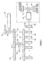
- the apparatus of the present invention has a microphone 10, as a first input, connected to a preamplifier 12, which in turn is connected to an analog-to-digital (A/D) converter 14.
- A/D analog-to-digital
- a secondary input 11 (which may also comprise a microphone) may also be connected to a preamplifier 13 which is in turn connected to an analog-to-digital (A/D) converter 15.
- Figure 1 shows an audio input signal or signals, the present invention is not limited to use with such signals and can have other information signals, such as a seismological signal, as an input.
- the term monaural describes embodiments which process one digital stream and the term stereo describes embodiments which process two digital streams.
- Theoretically according to the Nyquist Sampling Theorem, provided a signal is sampled at a rate of at least twice the input signal bandwidth, there will be adequate information content to reconstruct the signal. This minimum sampling rate required for reconstruction is commonly referred to as the Nyquist rate.
- the output of the A/D converter 14 (and where a secondary input exists, the output of A/D converter 15) is connected to a filterbank application specific integrated circuit (ASIC) 16 as shown in Figure 1 or, alternatively, directly to a programable DSP unit 18 via a synchronous serial port. Additional A/D converters (not shown) may be provided to permit digital processing of multiple separate input signals. Further input signals may be mixed together in the analog domain prior to digitization by these A/D converters. Mixing may also be done in the digital domain using the programmable DSP prior to processing by a monaural filterbank.
- the output of the filterbank ASIC 16 is connected to a digital-to-analog (D/A) converter 20.
- the converter 20 is in turn connected through a power amplifier 22 to a hearing aid receiver 24.
- the filtered signal in known manner, is converted back to an analog signal, amplified and applied to the receiver 24.
- the output of the A/D converter 14, and any additional A/D converter that is provided, may, instead of being connected to the ASIC 16 as shown, be connected to the programmable DSP 18 via a synchronous serial port.
- the output D/A converter 20 can alternatively be connected to the programmable DSP 18.
- an analysis filterbank 26 that splits or divides the digital representation of the input signal or signals into a plurality of separate complex bands 1-N. As shown in Figure 1, each of these bands is multiplied by a desired gain in a respective multiplier 28. In the case of monaural processing, the negative frequency bands are complex conjugate versions of the positive frequency bands. As a result, the negative frequency bands are implicitly known and need not be processed.
- the outputs of the multipliers 28 are then connected to inputs of a synthesis filterbank 30 in which these outputs are recombined to form a complete digital representation of the signal.
- the complex conjugate symmetry property does not hold.
- the N band outputs are unique and represent the frequency content of two real signals.
- the band outputs must first be processed to separate the content of the two signals from each other into two frequency domain signals before the gain multiplication step is performed.
- the two frequency separated signals are complex conjugate symmetric and obey the same redundancy properties as described previously for monaural processing.
- Multiplier resource 28 must, therefore, perform two sets of gain multiplications for the non-redundant (i.e. positive frequency) portion of each signal. After multiplication, the signals are combined into a monaural signal, and further processing is identical to the monaural case.
- the band outputs from the analysis filterbank 26 are downsampled or decimated. Theoretically, it is possible to preserve the signal information content with a decimation factor as high as N, corresponding to critical sampling at the Nyquist rate. This stems from the fact that the bandwidth of the N individual band outputs from the analysis filterbank 26 is reduced by N times relative to the input signal. However, it was found that maximum decimation, although easing computational requirements, created severe aliasing distortion if adjacent band gains differ greatly. Since this distortion unacceptably corrupts the input signal, a lesser amount of decimation was used.
- the band outputs are oversampled by a factor OS times the theoretical minimum sampling rate.
- the factor OS represents a compromise or trade-off, with larger values providing less distortion at the expense of greater computation (and hence power consumption).
- the factor OS is made a programmable parameter by the DSP.
- a time folding structure is used as is shown in the transform-based filter bank of Figure 3, and described in greater detail below.
- a window function which is also referred to as a prototype low pass filter
- the resulting signal is broken into segments, stacked and added together into a new signal.
- This signal is real for monaural applications and complex for stereo applications.
- the output of the analysis filterbank is the (even or odd) discrete Fourier transform (DFT) of this segment signal (the DFT is normally implemented with a fast Fourier transform algorithm).
- DFT discrete Fourier transform
- the odd DFT is an extension of the even or regular DFT as described in Bellanger, M., Digital Processing of Signals, (John Wiley and Sons, 1984), which is incorporated herein by reference.
- the present invention comprises a transform-based filterbank in which the action of the DFT is as a modulator or replicator of the frequency response of the prototype low pass filter (i.e. the window function), so that the discrete Fourier transform of the windowed time domain signal or signals results in a series of uniformly spaced frequency bands which are output from the analysis filterbank.
- the time-folding structure of the present invention further allows the number of frequency bands and their width to be programmable.
- this time-folding structure reduces the size of the DFT from the window size to the segment size and reduces complexity when the desired number of filter bands is less than the window size.
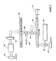
- This technique is shown generally for a filterbank of window size L and DFT size N in Figure 3.
- N full frequency bands including both non-negative and negative frequency bands, represented by N frequency band signals.
- these bands i.e. the band signals
- the frequency content of the two input signal streams are first separated as shown in Fig. 3a.
- the negative frequency bands are redundant because they can be exactly derived from the positive frequency bands (since they are complex conjugate versions of each other).
- the positive frequency bands i.e. the positive frequency band signals
- the non-positive frequency bands i.e. the non-positive frequency band signals.
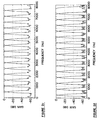
- there are N/2 non-negative complex frequency bands of normalized width 2 ⁇ N for odd stacking; and there are N/2 - 1 non-negative complex frequency bands of width 2 ⁇ N and 2 non-negative real frequency bands of width ⁇ N for even stacking. This is illustrated in Figure 2a for N 8.
- each filterbank channel is band limited to 2 ⁇ N and each band output can be decimated by the factor R (i.e. its sampling rate is reduced by keeping only every Rth sample) without, theoretically, any loss of fidelity if R ⁇ N.
- R the decimation factor
- the delay created by the FIFO shifting is smaller by the factor OS.
- the overlap-add analysis filterbank 26 includes an input 50 for R samples.
- the input 50 is connected to a multiplication unit 52 which also has an input connected to a circular ⁇ sign sequencer input 54 having a length of 2*OS samples.
- This circular sequencer input 54 which may be generated by a shift register, has a series of inputs for odd stacking of the filter bands and inputs for even stacking of the filter bands.
- each block of R input samples is multiplied by +1, so as to remain unchanged.
- the even DFT which has basis functions ending in the same sign (i.e. which are continuous)
- no modulation is required to obtain continuous basis functions.
- the first OS blocks of R input samples are multiplied by +1 and the next OS blocks by -1, the next OS blocks by +1, etc. Since the odd DFT has basis functions ending in opposite signs (i.e. which are not continuous), this modulation serves to produce continuous basis functions.
- the output of the multiplication unit 52 is connected to a first buffer 56 holding L samples, indicated as X(1:L). These samples are split up into individual segments 57, each of which contains R samples.
- the buffer 56 is sized so that the L samples form a desired window length. The larger the window length L, the more selective each channel becomes at the expense of additional delay.
- the buffer 56 is connected to a second multiplication unit 58, together with a window function 60, indicated as W(1:L).
- the modulation property of the fast Fourier transform procedure creates a complete uniformly spaced filterbank by replicating the frequency response of the window function (also referred to as the prototype low-pass filter) at equally spaced frequency intervals. It is necessary to properly design this window function to give a desired passband and stopband response to the filter bands and thereby reduce audible aliasing distortion.
- the window function (which is a prototype low pass filter) ideally satisfies the requirements for a good M-band filter, i.e. a good low pass filter which has zeros at every interval of N samples.
- Other window functions can also be used. See Vaidyanathan, P.P., “Multirate Digital Filters, Filter Banks, Polyphase Networks, and Applications: A tutorial", Proc. IEEE, Vol. 78, No. 1, pp. 56-93 (January 1990), which is incorporated herein by this reference.
- this filter may be designed as a windowed sinc function or by using Eigenfilters (see Vaidyanathan, P.P., and Nguyen, T.Q., "Eigenfilters: A New approach to least-squares FIR filter design and applications including Nyquist filters", IEEE Trans. on Circuits and Systems, Vol. 40, No. 4 (December 1994), pp. 11-23).
- the coefficients of the window function are generated by the programmable DSP or generated and stored in non-volatile memory.
- a general window is typically stored in non-volatile memory, however for the parametric classes of windows based on the sinc function, the window function need not be stored as it may be calculated on system initialization using only a few parameters.
- the output of the second multiplication unit 58 is connected to a second output buffer 62.
- This output buffer 62 again has the same L samples, arranged into segments 64.
- the segments contain N samples.
- N might equal 32 and the number of channels is 16 (for an odd DFT/odd stacking) or 17 (for an even DFT/even stacking -- because of the two half bands).
- a window length L of 256 samples can be used (the window length L is constrained to be a multiple of N, and in preferred embodiments is also a multiple of 2 N for computational simplicity) and the over-sampling factor, OS, should be 2 or greater.
- OS over-sampling factor
- R i.e N/OS
- the samples are real, and for stereo applications the samples are complex.
- the segments are separated, and as indicated below the buffer 62, individual segments 64 are added to one another to effect the time folding or time aliasing operation, and thereby reduce the number of necessary computations in processing the input signal or signals.
- the details of the time folding step are described in Crochiere, R.E. and Rabiner, L.R., Multirate Digital Signal Processing, supra. Ideally, the time folding step does not result in any loss of information, and in practical implementations any resulting loss can be made insignificant.
- the time aliased stacked and summed total is then subject to an odd FFT, or even FFT as required, by the FFT unit 68 (as shown in Figure 3 for monaural applications) or the FFT unit 68' (as shown in Figure 3a for stereo applications) to produce the DFT.
- the DFT provided by 68 is an N-point transform with real inputs (monaural), and the DFT provided by 68' is an N-point transform with complex inputs (stereo).
- the non-negative frequency components of the DFT output by the FFT unit 68, and a set of gain values G(1:N/2) for odd stacking (or G(1:N/2 + 1) for even stacking) from a multiplier resource unit 70, are connected to a multiplication unit 72.
- the two channels must first, i.e. before the multiplication step, be separated in a stereo channel separation step indicated at 76.
- a stereo channel separation step indicated at 76.
- the filterbank operation is linear, the resulting output from the analysis filterbank is X1 + jX2, where X1 and X2 are also N samples long.
- the frequency information of the two channels X1 and X2 are separable by using the symmetry relationships present in the N band outputs (i.e.
- the first channel spectrum has a symmetric real portion and an anti-symmetric imaginary portion
- the second channel has an anti-symmetric real portion and a symmetric imaginary portion
- the non-negative frequency components of these data streams are each multiplied by a separate set of gain values from multiplier resources 70A and 70B respectively (multiplier resources 70A and 70B typically represent the separate processing of the left and right channels, and each contains N/2 values for odd stacking or N/2 + 1 values for even stacking).
- multiplier resources 70A and 70B typically represent the separate processing of the left and right channels, and each contains N/2 values for odd stacking or N/2 + 1 values for even stacking).
- the two channels are combined in a combine channels step indicated at 78, which provides an output 74 as in the monaural case.
- the combination step 78 is simply the point by point summation of the two frequency domain streams.
- the multiplication units 72 of Fig 3 and 72A and 72B of Fig. 3a are equivalent to the multiplication units 28 shown in Figure 1.
- FIG. 4 shows the corresponding synthesis filterbank.
- the input is shown at 80 of the complex representation of the signal in the frequency domain, U(1:N/2) for odd stacking (or U(1:N/2 +1) for even stacking).
- This is converted to the time domain by an inverse DFT, which again is odd or even as required and which is implemented by the inverse FFT (IFFT) algorithm unit 82.
- IFFT inverse FFT
- the IFFT unit 82 produces a real output.
- the N-sample output of the circular shift sequence 84, Z'(1:N), is replicated and concatenated as necessary to form an L / DF sample sequence in input buffer 86, where DF represents the synthesis window decimation factor (and is not to be confused with the analysis filterbank time domain decimation factor R).
- DF represents the synthesis window decimation factor (and is not to be confused with the analysis filterbank time domain decimation factor R).
- the parameter DF is less than or equal to OS when the synthesis window function is based on a decimated version of the analysis function; otherwise DF equals 1.
- This replication and concatenation step is the inverse operation of the time aliasing step previously described. As illustrated in Figure 4, this input buffer is shown as L / DF*N N-sample segments which have been periodically extended from the circular shift sequence 84.
- L / DF*N may be a non-integer fraction.
- DF, L / DF*N may also be less than 1, and in such cases the input buffer 86 becomes shorter than N samples and comprises only the central portion of Z'(1:N).
- the output of the buffer 86 is connected to a multiplication unit 88.
- the multiplication unit 88 has another input for a synthesis window 89 indicated as W(1:DF:L).
- the window 89 which is L/DF samples long removes unwanted spectral images.
- the latter may be based on the decimated analysis window by setting DF ⁇ OS if the "droop" (or attenuation) of the analysis filter at its cutoff frequency divided by DF, i.e. at ⁇ N ⁇ DF , is not significant since this represents the attenuation of the synthesis window at ⁇ N .
- the synthesis window function is generated by decimating the analysis window coefficients by a factor of DF ⁇ OS.
- This constraint i.e. having the synthesis window based on the analysis window
- L corresponds to the number of samples held in the buffer 56 in the analysis filterbank ( Figure 3)
- DF represents the synthesis window decimation factor, where for DF equal to 2 every other sample is deleted.
- the synthesis window function W(1:DF:L) (this notation indicates a vector derived from a vector W by starting at index 1 and selecting every DF'th sample not exceeding index L) is ideally a good M-band filter, i.e. a good low pass filter which has zeros at every interval of N/DF samples.
- the output of the multiplication unit 88 is connected to a summation unit 90.
- the summation unit 90 has an output unit connected to an output buffer 92.
- the buffer 92 has an input at one end for additional samples and an additional sample input 94, so that the output buffer 92 acts like a shift register that shifts R samples each time a new input block is received.
- the output of the summation unit 90 is supplied to the buffer 92.
- the contents of the buffer 92 are periodically shifted to the left by R samples. This is achieved by adding R zeros to the right hand end of the buffer 92, as viewed. Following this shift, the contents of the buffer 92 are added to the product of W(1:DF:L) and the periodically extended buffer 86.
- the result is stored in the buffer 92 which holds L / DF samples (or equivalently L / DF*N N-sample segments).
- the buffer 92 may be less than one N-sample in length for large synthesis window decimation factors, DF.
- the output from the buffer 92 is a signal which in effect has been added L / (DF•R) times, so as to comprise portions of signals added together.
- the present invention allows for a selectable number of channels, and a selectable range of bandwidths.
- the selectable even/odd stacking feature permits the bands to be shifted in unison by half of the channel bandwidth, without increasing delay.
- the present invention allows the number of channels or bands and the width of those bands to be selected.
- R samples at a time are taken from the buffer 92 and sent to a multiplication unit 96.
- a multiplication unit 96 Mirroring the circular ⁇ sign sequencer input 54, there is another circular ⁇ sign sequencer input 98, which again has a series of multiplication factors of +1 or -1, depending upon whether an odd or even DFT is executed. This step exactly undoes the modulation step performed in the analysis stage.
- R samples are present at the output 100, as indicated as Y(1:R). These samples are fed to the D/A converter 20.
- the resynthesis procedure in addition to generating the correct signal in each band, produces unwanted spectral images which, when over-sampled by OS, are spaced OS times farther apart than for critical sampling.
- the synthesis window performs the function of removing these images similar to the function of the analysis window in preventing aliasing. Since these window functions are related, when memory is scarce, it is preferable to use a synthesis window related to the analysis window in order to conserve memory.
- the reconstruction window can conveniently be the synthesis window decimated by DF, the synthesis window decimation factor.
- connections to a programmable DSP 18 are provided, to enable the DSP to implement a particular processing strategy.
- the programmable DSP 18 comprises a processor module 34 including a volatile memory 36.
- the processor 34 is additionally connected to a nonvolatile memory 38 which is provided with a charge pump 40.
- various communication ports are provided, namely: a 16 bit input/output port 42, a synchronous serial port 44 and a programming interface link 46.
- the frequency band signals received by the DSP 18 represent the frequency content of the different bands and are used by the digital signal processor 34 to determine gain adjustments, so that a desired processing strategy can be implemented.
- the gains are computed based on the characteristics of the frequency band signals and are then supplied to the multipliers 28. While individual multipliers 28 are shown, in practice, as already indicated these could be replaced by one or more multiplier resources shared amongst the filterbank bands. This can be advantageous, as it reduces the amount of processing required by the DSP, by reducing the gain update rate and by allowing further computations to be done by the more efficient ASIC. In this manner, the memory requirements are also reduced and the DSP unit can remain in sleep mode longer.
- the processor 34 can be such as to determine when gain adjustments are required. When gain adjustments are not required, the whole programmable DSP unit 18 can be switched into a low-power or standby mode, so as to reduce power consumption and hence to extend battery life.
- the multipliers 28 are omitted from the ASIC.
- the outputs from the analysis filterbank 26 would then be supplied to the digital signal processor 34, which would both calculate the gains required and apply them to the signals for the different bands.
- the thus modified band signals would then be fed back to the ASIC and then to the synthesis filterbank 30. This would be achieved by a shared memory interface, which is described below.
- Communication between the ASIC 16 and the programmable DSP 18 is preferably provided by a shared memory interface.
- the ASIC 16 and the DSP 18 may simultaneously access the shared memory, with the only constraint being that both devices cannot simultaneously write to the same location of memory.
- Both the ASIC 16 and programmable DSP 18 require non-volatile memory for storage of filter coefficients, algorithm parameters and programs as indicated at 38.
- the memory 38 can be either electrically erasable programmable read only memory (EEPROM) or Flash memory that can be read from or written to by the processor 34 as required. Because it is very difficult to achieve reliable operation for large banks (e.g., 8 kbyte) of EEPROM or Flash memory at low supply voltages (1 volt), the charge-pump 40 is provided to increase the non-volatile memory supply voltage whenever it is necessary to read from or write to non-volatile memory. Typically, the non-volatile memory 38 and its associated charge pump 40 will be enabled only when the whole apparatus or hearing aid "boots"; after this it will be disabled (powered down) to reduce power consumption.
- Program and parameter information are transmitted to the digital signal processor 34 over the bi-directional programming interface link 46 that connects it to a programming interface.
- the programming interface link 46 or the audio link through the microphone 10 (and optional second microphone for a stereo implementation) provide a selection input enabling the number of frequency bands, the width of each band, even or odd stacking, and other parameters to be selected.
- This interface receives programs and parameter information from a personal computer or dedicated programmer over a bi-directional wired or wireless link. When connected to a wired programming interface, power for non-volatile memory is supplied by the interface; this will further increase the lifetime of the hearing aid battery.
- a specially synthesized audio band signal can also be used to program the digital filterbank hearing aid.
- the synchronous serial port 44 is provided on the DSP unit 18 so that an additional analog-to-digital converter can be incorporated for processing schemes that require two input channels (e.g., beamforming - beamforming is a technique in the hearing aid art enabling a hearing aid with at least two microphones to focus in on a particular sound source).
- beamforming - beamforming is a technique in the hearing aid art enabling a hearing aid with at least two microphones to focus in on a particular sound source.
- the programmable DSP 34 also provides a flexible method for connecting and querying user controls.
- a 16-bit wide parallel port is provided for the interconnection of user controls such as switches, volume controls (shaft encoder type) and for future expansion. Having these resources under software control of the DSP unit 18 provides flexibility that would not be possible with a hardwired ASIC implementation.
- error checking or error checking and correction can be used on data stored in non-volatile memory.
- the hearing aid Whenever it is powered on, the hearing aid will also perform a self-test of volatile memory and check the signal path by applying a digital input signal and verifying that the expected output signal is generated.
- a watchdog timer is used to ensure system stability. At a predetermined rate, this timer generates an interrupt that must be serviced or the entire system will be reset. In the event that the system must be reset, the digital filterbank hearing aid produces an audible indication to warn the user.
- a number of sub-band coded (i.e., digitally compressed) audio signals can be stored in the non-volatile memory 38 and transferred to volatile memory (RAM) 36 for real-time playback to the hearing aid user.
- the sub-band coding can be as described in chapters 11 and 12 of Jayant, N.S. and Noll, P., Digital Coding of Waveforms (Prentice-Hall; 1984) which is incorporated herein by this reference. These signals are used to provide an audible indication of hearing aid operation.
- Sub-band coding of the audio signals reduces the storage (non-volatile memory) that is required and it makes efficient use of the existing synthesis filterbank and programmable DSP because they are used as the sub-band signal decoder.
- the digital processing circuit consists of an analysis filterbank that splits the digital representation of the input time domain signal into a plurality of frequency bands, a means to communicate this information to/from a programmable DSP and a synthesis filterbank that recombines the bands to generate a time domain digital output signal.
- a digital hearing aid or indeed any hearing aid, would have non-uniform frequency bands that provide high resolution in frequency only where it is required. This would minimize the number of bands, while enabling modification of the gain or other parameters only where required in the frequency spectrum.
- the most efficient implementation of multi-channel filters where the implementation is based on known transforms such as the Fourier transform, have uniform spacing. This naturally results from the fact that uniform sampling in time maps to uniform spacing in frequency.
- the present invention provides a multi-channel filter design with uniform spacing.
- the number of bands, i.e. frequency resolution, required by a digital hearing aid depends upon the application.
- a digital hearing aid should be capable of adjustment in 250 Hz frequency steps. This fine adjustment allows the low-frequency gain targets at audiometric frequencies (the standard frequencies at which hearing characteristics are measured) to be accurately set.
- the sampling rate used by a digital hearing aid is related to the desired output bandwidth. Since speech typically has little energy above 5 kHz and covering this frequency range results in highly intelligible speech, a sampling rate of 16 kHz, corresponding to a bandwidth of 8 kHz was chosen to allow a margin for safety. At a proportional increase in power consumption, however, a sampling rate of 24 kHz or beyond may prove desirable for higher fidelity. The minimum sampling rate required to achieve a desired output bandwidth should be selected to minimize power consumption. Adequate frequency coverage and resolution is achieved by using sixteen 500 Hz wide bands. This in turn requires a 32-point discrete Fourier transform. Although the bands are 500 Hz wide inthis typical embodiment, the band edges may be adjusted in unison by 250 Hz steps. This is accomplished through the use of the DFT with even or odd stacking.
- Compressor systems which attempt to map variations in input signal level to smaller variations in output level, typically employ two or more bands so that high-level sounds in one band do not reduce the gain in other bands and impair speech perception.
- some results and opinions cast doubts on past results and methodologies that were used to evaluate multichannel compression systems.
- the filters should have small bandwidths to avoid removing speech harmonics. For the 8 kHz bandwidth mentioned, 128 bands provide bandwidths of 62.5 Hz which is adequate to avoid this problem.
- the filterbanks 26, 30 provide a number of bands, which is a programmable parameter. In accordance with the discussion above, the number of bands is typically in the range of 16-128.
- a further increase in low-frequency resolution may be obtained by further processing of one or more analysis filterbank output samples. This processing causes additional system delays since the additional samples must be acquired first before processing. This technique may be acceptable at low frequencies and for certain applications.
- FIR filterbanks are usually preferred, because they exhibit better performance in fixed-point implementations, are easier to design and of constant delay.
- Frequency bands in a filterbank can be non-overlapping, slightly overlapping or substantially overlapped.
- slightly overlapped designs are preferred, because they retain all frequency domain information while providing lower interaction between adjacent bands.
- the bands would be designed to abut precisely against each other with no overlap. This however would require very large order filters with unacceptably large delay, so in practice low-order filters (128 to 512 points) are used, which creates slightly overlapped designs.
- uniform spacing of the bands is provided, because they can be implemented using fast frequency-domain transforms, e.g. either a FFT or a discrete cosine transform, which require less computation than time-domain implementations.
- fast frequency-domain transforms e.g. either a FFT or a discrete cosine transform
- Some types of hearing loss result in precipitous losses or other types of losses which vary significantly across the frequency spectrum, which in turn requires the filterbank gains to vary over a wide dynamic range with respect to each other.
- This can provide a co-operative arrangement, in which the fixed or prefilter provides a coarse adjustment of the frequency response. This then leaves the analysis filterbank to provide a fine, dynamic adjustment and the problems of widely varying gains between adjacent filter bands are avoided.
- the filterbank structure of the present invention provides a natural structure for the generation of pure tones at the centre frequencies of each filter band. As these tones hit a majority of the audiometric frequencies that are employed to measure hearing loss, the filterbank can be programmed to emit pure tones. With these pure tones, the hearing aid can be used directly, to assess hearing loss, replacing the audiometer currently used and making the test more accurate and realistic.
- a postfilter can be added after the synthesis filterbank 30.
- the hearing aid can become acoustically unstable.
- the postfilter would act as a notch filter, to remove only the narrow band of oscillatory frequencies, while leaving the rest of the filter band alone. Alternatively, this can also be accomplished in the filterbank itself.
Landscapes
- Physics & Mathematics (AREA)
- Engineering & Computer Science (AREA)
- Computer Hardware Design (AREA)
- Mathematical Physics (AREA)
- Acoustics & Sound (AREA)
- General Health & Medical Sciences (AREA)
- Otolaryngology (AREA)
- Signal Processing (AREA)
- Health & Medical Sciences (AREA)
- Neurosurgery (AREA)
- Networks Using Active Elements (AREA)
- Compression, Expansion, Code Conversion, And Decoders (AREA)
- Stereophonic System (AREA)
- Tone Control, Compression And Expansion, Limiting Amplitude (AREA)
- Signal Processing Not Specific To The Method Of Recording And Reproducing (AREA)
- Electroluminescent Light Sources (AREA)
Claims (51)
- Banc de filtres pour filtrer un signal d'information, la structure de banc de filtres comprenant un moyen de filtre définissant une largeur de bande de filtre, ledit moyen de filtre filtrant ledit signal audio et séparant ledit signal audio en une pluralité de signaux de bande de fréquence représentant chacun l'une parmi une pluralité de bandes de fréquence uniformément espacées dans ladite largeur de bande de filtre, lesdites bandes de fréquence étant empilées d'une manière régulière ou irrégulière et lesdites bandes de fréquence étant en butée, se chevauchant ou étant espacées les unes par rapport aux autres, lesdits signaux de bande de fréquence étant sous-échantillonnés d'un facteur de décimation, caractérisé en ce que :le moyen de filtre comprend une entrée de sélection (46) permettant qu'au moins l'un des suivants soit sélectionné :(i) le nombre de signaux de bande de fréquence,(ii) la largeur de bande desdites bandes de fréquence,(iii) que lesdites bandes de fréquence soient empilées d'une manière régulière ou irrégulière,(iv) que lesdites bandes de fréquence soient en butée, se chevauchent ou soient espacées les unes par rapport aux autres, et(v) le facteur de décimation pour sous-échantillonner lesdits signaux de bande de fréquence.
- Banc de filtres selon la revendication 1, dans lequel l'entrée de sélection (46) permet qu'au moins l'une parmi le nombre de bandes de fréquence et que lesdites bandes de fréquence soient empilées de manière régulière ou irrégulière soit sélectionné, ledit nombre de bandes de fréquence étant égal à N, et le moyen de filtre comprend :a) un premier moyen de banc de filtres d'analyse (26) pour séparer ledit signal en la pluralité de N signaux de bande de fréquence séparés ;b) un moyen de traitement (34) pour recevoir et traiter chacun desdits signaux de bande de fréquence séparés pour générer N signaux de bande de fréquence traités séparés ; etc) un second moyen de banc de filtres de synthèse (30) pour recevoir et recombiner les N signaux de bande de fréquence traités séparés en un signal de sortie unique, dans lequel le premier moyen de banc de filtres d'analyse (26) et le second moyen de banc de filtres de synthèse (30) sont connectés à l'entrée de sélection (46), le moyen de traitement (34) étant couplé entre le premier moyen de banc de filtres d'analyse (26) et le second moyen de banc de filtres de synthèse (30).
- Banc de filtres selon la revendication 2, qui comprend un circuit intégré à application spécifique (ASIC) dédié (16), ledit ASIC (16) comprenant le premier banc de filtres d'analyse (26) et le second banc de filtres de synthèse (30), et un processeur de signal numérique programmable (18) pour contrôler le nombre de bandes de fréquence et la largeur de bande de chaque bande de fréquence, ledit processeur de signal numérique (18) étant pourvu de l'entrée de sélection (46).
- Banc de filtres selon la revendication 3, dans lequel ledit moyen de traitement (34) comprend un moyen multiplicateur (28) pour multiplier chacun des signaux de bande de fréquence par un gain ajustable pour générer les N signaux de bande de fréquence traités séparés.
- Banc de filtres selon la revendication 4, dans lequel le premier moyen de banc de filtres d'analyse (26) comprend un moyen de transformée (68) pour transformer le signal audio en domaine de fréquence, les N signaux de bande de fréquence séparés étant présents dans le domaine de fréquence, et le second moyen de banc de filtres de synthèse (30) comprend un moyen de transformée inverse (82) pour transformer les N signaux de bande de fréquence séparés en le signal de sortie unique dans le domaine temporel.
- Banc de filtres selon la revendication 5, qui est adapté pour recevoir un signal d'information monaural réel unique, dans lequel ledit moyen de transformée (68) génère des signaux de bande de fréquence non négatifs et des signaux de bande de fréquence négatifs, lesdits signaux de bande de fréquence négatifs étant dérivables à partir des signaux de bande de fréquence non négatifs, et ledit moyen de traitement (34) traite uniquement lesdits signaux de bande de fréquence non négatifs.
- Banc de filtres selon la revendication 5, dans lequel le banc de filtres est adapté pour filtrer un signal audio comprenant des premier et second signaux d'information monauraux réels qui sont combinés en un signal stéréo complexe et dans lequel dans lequel ledit moyen de transformée (68) génère N signaux de bande de fréquence combinés, et dans lequel ledit moyen de traitement (34) comprend :a) un moyen de séparation de canal (76) pour séparer les N signaux de bande de fréquence combinés en les N signaux de bande de fréquence correspondant audit premier signal d'information et les N signaux de bande de fréquence correspondant audit second signal d'information, chacun desdits N signaux de bande de fréquence comprenant des signaux de bande de fréquence non négatifs et négatifs ;b) un premier moyen de traitement de canal indépendant (70A) connecté au moyen de séparation de canal (76) pour recevoir et traiter chacun desdits signaux de bande de fréquence séparés dudit premier signal d'information pour générer un premier jeu de N signaux de bande de fréquence traités séparés ;c) un second moyen de traitement de canal indépendant (70B) connecté au moyen de séparation de canal (76) pour recevoir et traiter chacun desdits signaux de bande de fréquence séparés dudit second signal d'information pour générer un second jeu de N signaux de bande de fréquence traités séparés ; etd) un moyen de combinaison de canal (78) connecté aux premier (70A) et second (70B) moyens de traitement de canal indépendants pour combiner ledit premier jeu de N signaux de bande de fréquence traités séparés et ledit second jeu de signaux de bande de fréquence traités séparés.
- Banc de filtres selon la revendication 7, dans lequel lesdits premier (70A) et second (70B) moyens de traitement de canal indépendants traitent chacun uniquement les signaux de bande de fréquence non négatifs du signal d'information correspondant, les signaux de bande de fréquence négatifs étant dérivables à partir des signaux de bande de fréquence non négatifs.
- Banc de filtres selon la revendication 4, dans lequel le moyen multiplicateur (28) comprend une ou plusieurs ressources multiplicatrices dédiées incorporées sur le circuit intégré à application spécifique (16).
- Banc de filtres selon la revendication 4, dans lequel le moyen multiplicateur (28) comprend une ressource multiplicatrice disposée sur le processeur de signal numérique programmable (18).
- Banc de filtres selon la revendication 1, qui comprend une interface de mémoire partagée, pour interfaçage avec un processeur de signal numérique programmable (18).
- Banc de filtres selon la revendication 1, qui comprend un moyen de traitement de basse fréquence pour le traitement supplémentaire des bandes à basse fréquence pour produire une résolution supplémentaire.
- Banc de filtres selon la revendication 2, qui comprend un moyen de préfiltrage connecté au premier moyen de banc de filtres d'analyse (26), pour modifier le gain d'au moins une partie sélectionnée du spectre de fréquence dudit signal d'information.
- Banc de filtres selon la revendication 2 ou 13, qui comprend un moyen de post-filtrage connecté au second moyen de banc de filtres (30), pour post-filtrer le signal de sortie unique.
- Banc de filtres selon la revendication 3, dans lequel le premier moyen de banc de filtres d'analyse (26), le moyen de traitement (34) et le second moyen de banc de filtres de synthèse (30) utilisent un traitement de signal numérique, le premier moyen de banc de filtres d'analyse (26) étant adapté pour recevoir un train d'échantillon numérique d'entrée et le second moyen de banc de filtres de synthèse (30) émettant un train de données numériques de sortie en tant que signal de sortie dans lequel le circuit de banc de filtres comprend un moyen de conversion analogique-numérique (14) connecté audit premier banc de filtres d'analyse (26) pour recevoir un signal analogique original et pour convertir ledit signal analogique en un train d'échantillon numérique d'entrée à une fréquence d'échantillonnage d'entrée initiale qui forme ledit signal d'information pour le banc de filtres d'analyse (26) et un moyen de conversion numérique-analogique (20) connecté audit second banc de filtres de synthèse (30) pour convertir le train de données numériques de sortie pour former une version analogique dudit signal de sortie unique.
- Banc de filtres selon la revendication 15, dans lequel le premier moyen de banc de filtres d'analyse (26) comprend :a) un moyen de blocage pour recevoir le train d'échantillon numérique d'entrée et bloquer un premier nombre, R, où R ≤ N, des échantillons numériques de manière à générer un train d'échantillon numérique d'entrée bloqué (50), le rapport N/R correspondant à un facteur de suréchantillonnage ;b) un moyen de fenêtre d'analyse pour appliquer une fonction de fenêtre d'analyse (60) au train d'échantillon numérique d'entrée (50) pour générer un train d'échantillon numérique bloqué fenêtré (64), ladite fonction de fenêtre d'analyse (60) étant définie par un jeu de coefficients de fenêtre d'analyse ;c) un moyen de pliage temporel (66) pour superposer et additionner des blocs dudit train d'échantillon numérique bloqué fenêtré (64), chacun desdits blocs comprenant N échantillons numériques, pour générer un bloc sommé de N échantillons numériques ; etd) un moyen de transformée discrète (68) pour recevoir ledit bloc sommé de N échantillons numériques et transformer le signal en un signal de domaine de fréquence discret (74) ayant N composantes, les N composantes correspondant aux N signaux de bande de fréquence.
- Banc de filtres selon la revendication 16, dans lequel le second moyen de banc de filtres de synthèse (30) comprend :a) un moyen de transformée discrète inverse (82) pour recevoir lesdits N signaux de bande de fréquence traités et pour effectuer une transformée inverse pour former un bloc de N échantillons numériques ;b) un moyen de réplication et de concaténation (84) pour répliquer et concaténer ledit bloc traité de N échantillons numériques pour générer un bloc périodiquement étendu de N échantillons numériques ;c) un moyen de fenêtre de synthèse pour appliquer une fonction de fenêtre de synthèse (89) audit bloc étendu de N échantillons numériques pour générer un bloc périodiquement étendu fenêtré de N échantillons numériques, ladite fonction de fenêtre de synthèse (89) étant définie par un jeu de coefficients de fenêtre de synthèse ; etd) un moyen de tampon de sommation (92) pour recevoir ledit bloc périodiquement étendu fenêtré de N échantillons numériques et additionner lesdits échantillons périodiquement étendus fenêtrés au contenu décalé du tampon chaque fois qu'un nouvel échantillon périodiquement étendu fenêtré est reçu, de manière à générer un signal d'information traité.
- Banc de filtres selon la revendication 17, dans lequel ladite fonction de fenêtre de synthèse (89) est basée sur une version décimée de ladite fonction de fenêtre d'analyse (60).
- Banc de filtres selon la revendication 16 ou 17, dans laquelle le processeur de signal numérique programmable (18) est opérationnel pour faire varier ledit facteur de suréchantillonnage, et dans lequel le facteur de suréchantillonnage est égal à au moins 2.
- Banc de filtres selon la revendication 16, 17 ou 18 dans lequel le processeur de signal numérique programmable (18) est opérationnel pour faire varier lesdits coefficients de fenêtre d'analyse et lesdits coefficients de fenêtre de synthèse.
- Banc de filtres selon la revendication 3 dans lequel le processeur de signal numérique programmable (18) est opérationnel pour produire un empilage régulier ou un empilage irrégulier des bandes de fréquence dans ladite largeur de bande du système.
- Banc de filtres selon la revendication 1, 2 ou 3, dans lequel ledit banc de filtres est incorporé dans une prothèse auditive numérique.
- Appareil, pour utilisation dans une prothèse auditive numérique, caractérisé en ce que l'appareil comprend :un circuit intégré à application spécifique dédié (16), qui comprend un moyen de filtre d'analyse (26) pour séparer un signal en une pluralité de signaux de bande de fréquence différents dans différentes bandes de fréquence et un moyen de filtre de synthèse (30) pour recombiner les signaux de bande de fréquence en un signal de sortie ;un processeur de signal numérique programmable (18) ; etun moyen de multiplication (28) connecté au processeur de signal numérique programmable (18) et au circuit intégré à application spécifique (16), dans lequel le moyen de multiplication (28) multiplie chaque bande par un gain souhaité, et dans lequel le gain pour chaque bande est contrôlé par le processeur de signal numérique programmable (18) .
- Appareil selon la revendication 23, dans lequel le moyen de multiplication (28) est disposé sur le circuit intégré à application spécifique (16).
- Appareil selon la revendication 24, dans lequel le moyen de multiplication (28) comprend un multiplicateur unique qui est partagé entre les bandes de fréquence.
- Appareil selon la revendication 23, dans lequel le moyen de multiplication (28) comprend un multiplicateur-accumulateur, qui comprend une interface de mémoire partagée entre le circuit intégré à application spécifique (16) et le processeur de signal numérique programmable (18), pour effectuer la transmission de données entre le circuit intégré à application spécifique (16) et le processeur de signal numérique programmable (18).
- Appareil selon la revendication 23, dans lequel le processeur de signal numérique programmable (18) comprend un moyen de contrôle de puissance, permettant au processeur de signal numérique programmable d'être mis hors tension entre les calculs de gain afin de réduire la consommation d'énergie.
- Appareil selon la revendication 23, dans lequel le processeur de signal numérique programmable (18) comprend un processeur programmable (34), qui comprend une mémoire volatile (36) pour le processeur de signal numérique programmable (34), une mémoire non volatile (38) et un moyen d'alimentation assurant une lecture et une écriture fiables dans les mémoires.
- Appareil selon la revendication 28, dans lequel le moyen d'alimentation comprend une pompe de charge (40) connectée à la mémoire non volatile (38) et dans lequel le moyen d'alimentation comprend un moyen pour mettre hors tension la pompe de charge (40) et la mémoire non volatile (38), sous contrôle logiciel, après le démarrage initial du processeur de signal numérique programmable (18) et le chargement du programme et des données de paramètre dans la mémoire volatile (36).
- Appareil selon la revendication 28, qui comprend des signaux audio codés de sous-bande stockés dans la mémoire non volatile (38), signaux audio qui peuvent être décodés par le banc de filtres de synthèse (30) et le processeur de signal numérique programmable (18), pour transmettre des signaux audio à un utilisateur.
- Appareil selon l'une quelconque des revendications 23, 26 ou 28, qui comprend :un microphone (10) ;un préamplificateur (12) connecté au microphone (10) ;un convertisseur analogique-numérique (14) connecté au préamplificateur (12) et à une entrée du circuit intégré à application spécifique (16), entrée qui est connectée au moyen de filtre d'analyse (26) ;un convertisseur numérique-analogique (20) connecté à une sortie du moyen de filtre de synthèse (30) du circuit intégré à application spécifique (16) ;un amplificateur de puissance (22) connecté au convertisseur numérique-analogique (20) ; etun récepteur (24) connecté à la sortie de l'amplificateur de puissance (22).
- Appareil selon l'une quelconque des revendications 23, 26 ou 28, qui comprend :un premier préamplificateur (12) connecté à une première entrée (10) ;un deuxième préamplificateur (13) connecté à une deuxième entrée (11), au moins l'une des première et deuxième entrées comprenant un microphone (10) ;un premier convertisseur analogique-numérique (14) connecté au premier préamplificateur (12) ;un deuxième convertisseur analogique-numérique (15) connecté au deuxième préamplificateur (13), chacun desdits premier (14) et deuxième (15) convertisseurs analogique-numérique étant connecté à un port série synchrone (44) sur l'un parmi le processeur de signal numérique programmable (18) et le circuit intégré à application spécifique (16),un convertisseur numérique-analogique (20) connecté au même parmi le processeur de signal numérique programmable (18) et le circuit intégré à application spécifique (16) que les convertisseurs analogique-numérique (14) et (15) ;un amplificateur de puissance (22) connecté au convertisseur numérique-analogique (20) ; etun récepteur connecté à la sortie de l'amplificateur de puissance (22).
- Appareil selon la revendication 23, dans lequel le moyen de filtre d'analyse (26) comprend un premier moyen de banc de filtres d'analyse pour séparer ledit signal en N signaux de bande de fréquence séparés, et le moyen de banc de filtres de synthèse (30) comprend un second moyen de banc de filtres de synthèse pour recevoir et recombiner les N signaux de bande de fréquence traités séparés en un signal de sortie unique, et dans lequel l'appareil comprend une entrée de sélection (46) connectée au premier moyen de banc de filtres d'analyse (26) et au second moyen de banc de filtres de synthèse (30), pour permettre que le nombre de bandes et la largeur de bande de chaque bande de fréquence soient sélectionnés.
- Procédé de traitement d'un signal d'information pour modifier sélectivement différentes bandes de fréquence, caractérisé en ce que le procédé comprend les étapes de :(1) définition d'une largeur de bande de fréquence de filtre à analyser ;(2) division de la largeur de bande de filtre en une pluralité de bandes uniformément espacées, lesdites bandes de fréquence étant empilées d'une manière régulière ou irrégulière et lesdites bandes de fréquence étant en butée, se chevauchant ou étant espacées les unes par rapport aux autres ;(3) filtrage du signal d'information pour séparer le signal en une pluralité de signaux de bande de fréquence, représentant chacun l'une desdites bandes de filtre uniformes, lesdits signaux de bande de fréquence étant sous-échantillonnés d'un facteur de décimation ;(4) traitement des signaux de bande de fréquence ;(5) recombinaison des signaux des bandes individuelles pour former un signal de sortie ; et(6) génération d'une entrée (46) pour permettre qu'au moins l'un des suivants soit sélectionné :(i) le nombre de signaux de bande de fréquence,(ii) la largeur de bande desdites bandes de fréquence,(iii) que lesdites bandes de fréquence soient empilées d'une manière régulière ou irrégulière,(iv) que lesdites bandes de fréquence soient en butée, se chevauchent ou soient espacées les unes des autres, et(v) le facteur de décimation pour sous-échantillonner lesdits signaux de bande de fréquence.
- Procédé selon la revendication 34, dans lequel l'étape (4) comprend la définition d'un gain pour chaque bande de fréquence et la multiplication de chaque signal de bande de fréquence par le gain défini respectif.
- Procédé selon la revendication 34, le procédé comprenant en outre :a) dans l'étape (3), la séparation dudit signal en N signaux de bande de fréquence séparés ;b) dans l'étape (4), le traitement de chacun desdits signaux de bande de fréquence séparés pour générer N signaux de bande de fréquence traités séparés ;c) dans l'étape (5), la recombinaison des N signaux de bande de fréquence traités séparés pour former le signal de sortie ; etd) la sélection du nombre de bandes de fréquence ou que lesdits bandes de fréquence soient empilées d'une manière régulière ou irrégulière.
- Procédé selon la revendication 36, qui comprend la transformation du signal d'information en domaine de fréquence, en générant N signaux de bande de fréquence séparés dans le domaine de fréquence, et la conduite d'une transformée inverse des N signaux de bande de fréquence traités séparés en le signal de sortie dans le domaine temporel.
- Procédé selon la revendication 37, qui comprend la génération de signaux de bande de fréquence non négatifs et de signaux de bande de fréquence négatifs, les signaux de bande de fréquence négatifs étant dérivables à partir des signaux de bande de fréquence non négatifs, et, dans l'étape (4), le traitement uniquement desdits signaux de bande de fréquence non négatifs.
- Procédé selon la revendication 38, qui comprend :a) la réception d'un signal d'information comprenant des premier et deuxième signaux d'information monauraux réels combinés en un signal stéréo complexe et, lors de la transformation du signal d'information en domaine de fréquence, la génération de N signaux de bande de fréquence combinés ;b) la séparation des N signaux de bande de fréquence combinés en les N signaux de bande de fréquence correspondant audit premier signal d'information et les signaux de bande de fréquence correspondant audit deuxième signal d'information chacun desdits N signaux de bande de fréquence comprenant des signaux de bande de fréquence non négatifs et négatifs ;c) le traitement de chacun desdits signaux de bande de fréquence séparés dudit premier signal d'information pour générer un premier jeu de N signaux de bande de fréquence traités séparés ;d) le traitement de chacun desdits signaux de bande de fréquence séparés dudit deuxième signal d'information pour générer un deuxième jeu de N signaux de bande de fréquence traités séparés ; ete) la combinaison dudit premier jeu de N signaux de bande de fréquence traités séparés et dudit deuxième jeu de N signaux de bande de fréquence traités séparés.
- Procédé selon la revendication 39, qui comprend, pour chacun desdits premier et deuxième signaux d'information, le traitement uniquement des signaux de bande de fréquence non négatifs du signal d'information correspondant.
- Procédé selon la revendication 37, dans lequel le procédé est conduit par traitement de signal numérique, le procédé comprenant :le passage d'un signal analogique original à travers un moyen de conversion analogique-numérique (14) pour convertir le signal analogique en un train d'échantillon numérique d'entrée à une fréquence d'échantillonnage d'entrée initiale qui forme ledit signal d'information, et dans lequel le signal de sortie après la transformée inverse comprend un train de données numériques de sortie ; etla conduite d'une conversion numérique-analogique (20) du train de données numériques de sortie pour former une version analogique du signal de sortie.
- Procédé selon la revendication 41, dans lequel l'étape de transformation du signal d'information en domaine de fréquence comprend :a) le blocage du train d'échantillon numérique d'entrée en blocs de R échantillons, où R ≤ N, pour générer un train d'échantillon numérique d'entrée bloqué, le rapport N/R correspondant à un facteur de suréchantillonnage ;b) l'application d'une fonction de fenêtre d'analyse (60) au train d'échantillon numérique d'entrée pour générer un train d'échantillon numérique bloqué fenêtré, ladite fonction de fenêtre d'analyse (60) étant définie par un jeu de coefficients de fenêtre d'analyse ;c) la superposition et l'ajout de blocs dudit train d'échantillon numérique bloqué fenêtré, chacun desdits blocs comprenant N échantillons numériques, pour générer un bloc sommé de N échantillons numériques ; etd) la transformation du signal en un signal de domaine de fréquence discret ayant N composantes, les N composantes correspondant aux N signaux de bande de fréquence.
- Procédé selon la revendication 42, dans lequel l'étape de conduite d'une transformée inverse des N signaux de bande de fréquence traités séparés comprend :a) la conduite d'une transformée inverse pour former un bloc de N échantillons numériques ;b) la réplication et la concaténation dudit bloc traité de N échantillons numériques pour générer un bloc périodiquement étendu de N échantillons numériques ;c) l'application d'une fonction de fenêtre de synthèse (89) audit bloc étendu de N échantillons numériques pour générer un bloc périodiquement étendu fenêtré de N échantillons numériques, ladite fonction de fenêtre de synthèse (89) étant définie par un jeu de coefficients de fenêtre de synthèse ;d) l'ajout dudit bloc périodiquement étendu fenêtré de N échantillons à un tampon de sommation (92) ; ete) chaque fois qu'un nouvel échantillon périodiquement étendu fenêtré est reçu, le décalage du contenu du tampon de sommation (92) de R échantillons depuis une extrémité du tampon de sommation (92) vers l'autre extrémité du tampon (92), en disposant des zéros pour remplir les R échantillons vides à la première extrémité du tampon, et le passage des R échantillons déplacés hors de l'autre extrémité du tampon vers une sortie pour générer un signal d'information traité.
- Procédé selon la revendication 43, qui comprend la formation de la fonction de fenêtre de synthèse par décimation de la fonction de fenêtre d'analyse (89).
- Procédé selon les revendications 37, 41 ou 43, qui comprend la sélection de l'empilage des bandes de fréquence en l'un parmi un empilage régulier et un empilage irrégulier, dans la largeur de bande de fréquence.
- Procédé selon la revendication 34, qui comprend l'application du procédé à un signal d'information audio dans une prothèse auditive numérique.
- Procédé selon la revendication 46, comprenant l'amélioration des bandes de basse fréquence par traitement supplémentaire.
- Procédé selon la revendication 47, qui comprend la subdivision d'au moins une bande de basse fréquence en bandes plus petites pour traitement individuel.
- Procédé selon la revendication 46, qui comprend la sélection du nombre de bandes et de la largeur des bandes, en fonction des délais acceptables et de la résolution souhaitée.
- Procédé selon la revendication 42 ou 43 dans lequel le facteur de suréchantillonnage peut varier et est égal à au moins 2.
- Procédé selon la revendication 43 dans lequel les coefficients de fenêtre d'analyse et les coefficients de fenêtre de synthèse peuvent varier.
Applications Claiming Priority (5)
| Application Number | Priority Date | Filing Date | Title |
|---|---|---|---|
| US4199097P | 1997-04-16 | 1997-04-16 | |
| US4197797P | 1997-04-16 | 1997-04-16 | |
| US41990P | 1997-04-16 | ||
| US41977P | 1997-04-16 | ||
| PCT/CA1998/000329 WO1998047313A2 (fr) | 1997-04-16 | 1998-04-16 | Structure de banc de filtres et procede servant a filtrer et a separer un signal d'information en differentes bandes, en particulier pour des signaux sonores dans des protheses auditives |
Publications (2)
| Publication Number | Publication Date |
|---|---|
| EP0985328A2 EP0985328A2 (fr) | 2000-03-15 |
| EP0985328B1 true EP0985328B1 (fr) | 2006-03-08 |
Family
ID=26718755
Family Applications (1)
| Application Number | Title | Priority Date | Filing Date |
|---|---|---|---|
| EP98914754A Expired - Lifetime EP0985328B1 (fr) | 1997-04-16 | 1998-04-16 | Structure de banc de filtres et procede servant a filtrer et a separer un signal d'information en differentes bandes, en particulier pour des signaux sonores dans des protheses auditives |
Country Status (9)
| Country | Link |
|---|---|
| EP (1) | EP0985328B1 (fr) |
| JP (1) | JP4267078B2 (fr) |
| AT (1) | ATE320162T1 (fr) |
| AU (1) | AU744008B2 (fr) |
| CA (1) | CA2286051C (fr) |
| DE (1) | DE69833749T2 (fr) |
| DK (1) | DK0985328T3 (fr) |
| NO (1) | NO314609B1 (fr) |
| WO (1) | WO1998047313A2 (fr) |
Cited By (10)
| Publication number | Priority date | Publication date | Assignee | Title |
|---|---|---|---|---|
| US8411886B2 (en) | 2006-08-04 | 2013-04-02 | Siemens Audiologische Technik Gmbh | Hearing aid with an audio signal generator |
| US8976988B2 (en) | 2011-03-24 | 2015-03-10 | Oticon A/S | Audio processing device, system, use and method |
| EP2421282B1 (fr) | 2010-08-20 | 2016-10-12 | Sivantos Pte. Ltd. | Appareil d'aide auditive et/ou de traitement d'acouphène |
| US12266375B2 (en) | 2014-08-27 | 2025-04-01 | Fraunhofer-Gesellschaft Zur Foerderung Der Angewandten Forschung E.V. | Encoder, decoder and method for encoding and decoding audio content using parameters for enhancing a concealment |
| US12273519B2 (en) | 2014-07-28 | 2025-04-08 | Fraunhofer-Gesellschaft Zur Foerderung Der Angewandten Forschung E.V. | Encoder, decoder, system and methods for encoding and decoding |
| US12272365B2 (en) | 2013-02-20 | 2025-04-08 | Fraunhofer-Gesellschaft Zur Foerderung Der Angewandten Forschung E.V. | Apparatus and method for decoding an encoded audio or image signal using an auxiliary window function |
| US12315518B2 (en) | 2013-06-21 | 2025-05-27 | Fraunhofer-Gesellschaft Zur Foerderung Der Angewandten Forschung E.V. | Apparatus and method for improved concealment of the adaptive codebook in a CELP-like concealment employing improved pitch lag estimation |
| US12431148B2 (en) | 2014-03-31 | 2025-09-30 | Fraunhofer-Gesellschaft Zur Foerderung Der Angewandten Forschung E.V. | Encoding device, decoding device, encoding method, decoding method, and non-transitory computer-readable recording medium |
| US12475903B2 (en) | 2008-12-15 | 2025-11-18 | Fraunhofer-Gesellschaft Zur Foerderung Der Angewandten Forschung E.V. | Audio encoder and bandwidth extension decoder |
| US12633298B2 (en) | 2024-05-31 | 2026-05-19 | Fraunhofer-Gesellschaft Zur Foerderung Der Angewandten Forschung E.V. | Apparatus for encoding a speech signal employing ACELP in the autocorrelation domain |
Families Citing this family (19)
| Publication number | Priority date | Publication date | Assignee | Title |
|---|---|---|---|---|
| CA2396771A1 (fr) | 2000-01-20 | 2001-07-26 | Starkey Laboratories, Inc. | Systemes pour protheses auditives |
| ATE244979T1 (de) * | 2000-01-25 | 2003-07-15 | Widex As | Eine methode und ein system zur erzeugung eines kalibrierten schallfeldes |
| EP2066139A3 (fr) * | 2000-09-25 | 2010-06-23 | Widex A/S | Appareil d'aide auditive |
| EP1191813A1 (fr) | 2000-09-25 | 2002-03-27 | TOPHOLM & WESTERMANN APS | Prothèse auditive avec un filtre adaptatif pour la suppression de la réaction acoustique |
| EP1250027A1 (fr) | 2001-04-13 | 2002-10-16 | Widex A/S | Suppression de l' occlusion percue |
| JP4681163B2 (ja) * | 2001-07-16 | 2011-05-11 | パナソニック株式会社 | ハウリング検出抑圧装置、これを備えた音響装置、及び、ハウリング検出抑圧方法 |
| US7363334B2 (en) | 2003-08-28 | 2008-04-22 | Accoutic Processing Technology, Inc. | Digital signal-processing structure and methodology featuring engine-instantiated, wave-digital-filter componentry, and fabrication thereof |
| CA2481631A1 (fr) | 2004-09-15 | 2006-03-15 | Dspfactory Ltd. | Methode et systeme de traitement des signaux physiologiques |
| CA2581810C (fr) | 2004-10-26 | 2013-12-17 | Dolby Laboratories Licensing Corporation | Calcul et reglage de la sonie percue et/ou de l'equilibre spectral percu d'un signal audio |
| DK1675431T3 (en) | 2004-12-22 | 2016-02-08 | Bernafon Ag | Hearing aid with frequency channels |
| EP1742509B1 (fr) * | 2005-07-08 | 2013-08-14 | Oticon A/S | Système et procédé pour éliminer le bruit feed-back dans un dispositif auditif |
| US7676374B2 (en) | 2006-03-28 | 2010-03-09 | Nokia Corporation | Low complexity subband-domain filtering in the case of cascaded filter banks |
| BRPI0709877B1 (pt) * | 2006-04-04 | 2019-12-31 | Dolby Laboratories Licensing Corp | método e aparelho para controlar uma característica de intensidade acústica particular de um sinal de áudio |
| DE102008024490B4 (de) * | 2008-05-21 | 2011-09-22 | Siemens Medical Instruments Pte. Ltd. | Filterbanksystem für Hörgeräte |
| DE102008058496B4 (de) | 2008-11-21 | 2010-09-09 | Siemens Medical Instruments Pte. Ltd. | Filterbanksystem mit spezifischen Sperrdämpfungsanteilen für eine Hörvorrichtung |
| EP2980797A1 (fr) | 2014-07-28 | 2016-02-03 | Fraunhofer-Gesellschaft zur Förderung der angewandten Forschung e.V. | Décodeur audio, procédé et programme d'ordinateur utilisant une réponse d'entrée zéro afin d'obtenir une transition lisse |
| EP3499916B1 (fr) | 2017-12-13 | 2022-05-11 | Oticon A/s | Dispositif, système, utilisation et procédé de traitement audio |
| WO2020089757A1 (fr) | 2018-11-02 | 2020-05-07 | Cochlear Limited | Codage de multiples sources sonores dans des prothèses auditives |
| CN115902380B (zh) * | 2023-03-08 | 2023-06-16 | 保定天威新域科技发展有限公司 | 一种超宽带电流智能传感器 |
Family Cites Families (6)
| Publication number | Priority date | Publication date | Assignee | Title |
|---|---|---|---|---|
| DE3131193A1 (de) * | 1981-08-06 | 1983-02-24 | Siemens AG, 1000 Berlin und 8000 München | Geraet zur kompensation von gehoerschaeden |
| DK546581A (da) * | 1981-12-10 | 1983-06-11 | Danavox As | Fremgangsmaade til tilpasning af overfoeringsfunktionen i et hoereapparat til forskellige hoeredefekter samt hoereapparat til udoevelse af fremgangsmaaden |
| US5029217A (en) * | 1986-01-21 | 1991-07-02 | Harold Antin | Digital hearing enhancement apparatus |
| US4852175A (en) * | 1988-02-03 | 1989-07-25 | Siemens Hearing Instr Inc | Hearing aid signal-processing system |
| SE462885B (sv) * | 1989-06-29 | 1990-09-10 | Anders Sagren | Programmerbar hoerselkorrigerande anordning |
| US5651071A (en) * | 1993-09-17 | 1997-07-22 | Audiologic, Inc. | Noise reduction system for binaural hearing aid |
-
1998
- 1998-04-16 EP EP98914754A patent/EP0985328B1/fr not_active Expired - Lifetime
- 1998-04-16 AU AU69153/98A patent/AU744008B2/en not_active Expired
- 1998-04-16 AT AT98914754T patent/ATE320162T1/de not_active IP Right Cessation
- 1998-04-16 DE DE69833749T patent/DE69833749T2/de not_active Expired - Lifetime
- 1998-04-16 WO PCT/CA1998/000329 patent/WO1998047313A2/fr not_active Ceased
- 1998-04-16 JP JP54332898A patent/JP4267078B2/ja not_active Expired - Lifetime
- 1998-04-16 CA CA002286051A patent/CA2286051C/fr not_active Expired - Lifetime
- 1998-04-16 DK DK98914754T patent/DK0985328T3/da active
-
1999
- 1999-10-14 NO NO19995009A patent/NO314609B1/no not_active IP Right Cessation
Cited By (10)
| Publication number | Priority date | Publication date | Assignee | Title |
|---|---|---|---|---|
| US8411886B2 (en) | 2006-08-04 | 2013-04-02 | Siemens Audiologische Technik Gmbh | Hearing aid with an audio signal generator |
| US12475903B2 (en) | 2008-12-15 | 2025-11-18 | Fraunhofer-Gesellschaft Zur Foerderung Der Angewandten Forschung E.V. | Audio encoder and bandwidth extension decoder |
| EP2421282B1 (fr) | 2010-08-20 | 2016-10-12 | Sivantos Pte. Ltd. | Appareil d'aide auditive et/ou de traitement d'acouphène |
| US8976988B2 (en) | 2011-03-24 | 2015-03-10 | Oticon A/S | Audio processing device, system, use and method |
| US12272365B2 (en) | 2013-02-20 | 2025-04-08 | Fraunhofer-Gesellschaft Zur Foerderung Der Angewandten Forschung E.V. | Apparatus and method for decoding an encoded audio or image signal using an auxiliary window function |
| US12315518B2 (en) | 2013-06-21 | 2025-05-27 | Fraunhofer-Gesellschaft Zur Foerderung Der Angewandten Forschung E.V. | Apparatus and method for improved concealment of the adaptive codebook in a CELP-like concealment employing improved pitch lag estimation |
| US12431148B2 (en) | 2014-03-31 | 2025-09-30 | Fraunhofer-Gesellschaft Zur Foerderung Der Angewandten Forschung E.V. | Encoding device, decoding device, encoding method, decoding method, and non-transitory computer-readable recording medium |
| US12273519B2 (en) | 2014-07-28 | 2025-04-08 | Fraunhofer-Gesellschaft Zur Foerderung Der Angewandten Forschung E.V. | Encoder, decoder, system and methods for encoding and decoding |
| US12266375B2 (en) | 2014-08-27 | 2025-04-01 | Fraunhofer-Gesellschaft Zur Foerderung Der Angewandten Forschung E.V. | Encoder, decoder and method for encoding and decoding audio content using parameters for enhancing a concealment |
| US12633298B2 (en) | 2024-05-31 | 2026-05-19 | Fraunhofer-Gesellschaft Zur Foerderung Der Angewandten Forschung E.V. | Apparatus for encoding a speech signal employing ACELP in the autocorrelation domain |
Also Published As
| Publication number | Publication date |
|---|---|
| JP2001519127A (ja) | 2001-10-16 |
| NO995009L (no) | 1999-12-10 |
| DK0985328T3 (da) | 2006-04-10 |
| CA2286051A1 (fr) | 1998-10-22 |
| WO1998047313A2 (fr) | 1998-10-22 |
| DE69833749D1 (de) | 2006-05-04 |
| DE69833749T2 (de) | 2006-08-17 |
| WO1998047313A3 (fr) | 1999-02-11 |
| NO314609B1 (no) | 2003-04-14 |
| JP4267078B2 (ja) | 2009-05-27 |
| ATE320162T1 (de) | 2006-03-15 |
| NO995009D0 (no) | 1999-10-14 |
| AU744008B2 (en) | 2002-02-14 |
| HK1024814A1 (en) | 2000-10-20 |
| CA2286051C (fr) | 2003-03-11 |
| AU6915398A (en) | 1998-11-11 |
| EP0985328A2 (fr) | 2000-03-15 |
Similar Documents
| Publication | Publication Date | Title |
|---|---|---|
| US6240192B1 (en) | Apparatus for and method of filtering in an digital hearing aid, including an application specific integrated circuit and a programmable digital signal processor | |
| US6236731B1 (en) | Filterbank structure and method for filtering and separating an information signal into different bands, particularly for audio signal in hearing aids | |
| CA2286051C (fr) | Structure de banc de filtres et procede servant a filtrer et a separer un signal d'information en differentes bandes, en particulier pour des signaux sonores dans des protheses auditives | |
| Brennan et al. | A flexible filterbank structure for extensive signal manipulations in digital hearing aids | |
| KR100859348B1 (ko) | 워핑된 처리를 이용한 디지털 오디오의 동적 범위 제어 및등화 | |
| KR101726584B1 (ko) | 저 지연 변조 필터 뱅크 | |
| KR20110111409A (ko) | 분해된 오디오 신호의 재구성 시스템 및 방법 | |
| US20050018796A1 (en) | Method of combining an analysis filter bank following a synthesis filter bank and structure therefor | |
| US7492848B2 (en) | Method and apparatus for efficient multi-stage FIR filters | |
| Schneider et al. | An ultra low-power programmable DSP system for hearing aids and other audio applications | |
| Brennan et al. | An ultra low-power DSP system with a flexible filterbank | |
| HK1024814B (en) | Filterbank structure and method for filtering and separating an information signal into different bands, particularly for audio signals in hearing aids | |
| US11837244B2 (en) | Analysis filter bank and computing procedure thereof, analysis filter bank based signal processing system and procedure suitable for real-time applications | |
| Wu et al. | Design of discrete Fourier transform modulated filter bank with sharp transition band | |
| Parfieniuk et al. | Tunable non-uniform filter bank mixing cosine modulation with perceptual frequency warping by allpass transformation | |
| Sokolova et al. | Multirate audiometric filter bank for hearing aid devices | |
| JP2895713B2 (ja) | ステレオ音声信号のサブバンドフィルタリング方法及びその装置 | |
| Vieira | Digital five-band equalizer with linear phase | |
| US7205914B1 (en) | System and method for efficient upsampled signal processing | |
| Drollinger et al. | Efficient Sub-band Coder Implementation for Portable Low-power Applications | |
| JP5466054B2 (ja) | D/aコンバータ | |
| Lin et al. | High-Definition Audio Spectrum Separation via Frequency Response Masking Filter Banks | |
| Nikoleta | Compression techniques for digital hearing aids | |
| Samad et al. | An approach for low power hearing aids design | |
| HK1244112B (en) | Complex exponential modulated filter bank for high frequency reconstruction |
Legal Events
| Date | Code | Title | Description |
|---|---|---|---|
| PUAI | Public reference made under article 153(3) epc to a published international application that has entered the european phase |
Free format text: ORIGINAL CODE: 0009012 |
|
| 17P | Request for examination filed |
Effective date: 19991111 |
|
| AK | Designated contracting states |
Kind code of ref document: A2 Designated state(s): AT BE CH CY DE DK ES FI FR GB GR IE IT LI LU MC NL PT SE |
|
| RAP1 | Party data changed (applicant data changed or rights of an application transferred) |
Owner name: DSPFACTORY LTD. |
|
| GRAP | Despatch of communication of intention to grant a patent |
Free format text: ORIGINAL CODE: EPIDOSNIGR1 |
|
| GRAS | Grant fee paid |
Free format text: ORIGINAL CODE: EPIDOSNIGR3 |
|
| RAP1 | Party data changed (applicant data changed or rights of an application transferred) |
Owner name: EMMA MIXED SIGNAL C.V. |
|
| GRAA | (expected) grant |
Free format text: ORIGINAL CODE: 0009210 |
|
| AK | Designated contracting states |
Kind code of ref document: B1 Designated state(s): AT BE CH CY DE DK ES FI FR GB GR IE IT LI LU MC NL PT SE |
|
| PG25 | Lapsed in a contracting state [announced via postgrant information from national office to epo] |
Ref country code: NL Free format text: LAPSE BECAUSE OF FAILURE TO SUBMIT A TRANSLATION OF THE DESCRIPTION OR TO PAY THE FEE WITHIN THE PRESCRIBED TIME-LIMIT Effective date: 20060308 Ref country code: IT Free format text: LAPSE BECAUSE OF FAILURE TO SUBMIT A TRANSLATION OF THE DESCRIPTION OR TO PAY THE FEE WITHIN THE PRESCRIBED TIME-LIMIT;WARNING: LAPSES OF ITALIAN PATENTS WITH EFFECTIVE DATE BEFORE 2007 MAY HAVE OCCURRED AT ANY TIME BEFORE 2007. THE CORRECT EFFECTIVE DATE MAY BE DIFFERENT FROM THE ONE RECORDED. Effective date: 20060308 Ref country code: BE Free format text: LAPSE BECAUSE OF FAILURE TO SUBMIT A TRANSLATION OF THE DESCRIPTION OR TO PAY THE FEE WITHIN THE PRESCRIBED TIME-LIMIT Effective date: 20060308 Ref country code: AT Free format text: LAPSE BECAUSE OF FAILURE TO SUBMIT A TRANSLATION OF THE DESCRIPTION OR TO PAY THE FEE WITHIN THE PRESCRIBED TIME-LIMIT Effective date: 20060308 |
|
| REG | Reference to a national code |
Ref country code: GB Ref legal event code: FG4D |
|
| REG | Reference to a national code |
Ref country code: CH Ref legal event code: EP |
|
| REG | Reference to a national code |
Ref country code: SE Ref legal event code: TRGR |
|
| REG | Reference to a national code |
Ref country code: IE Ref legal event code: FG4D |
|
| REG | Reference to a national code |
Ref country code: DK Ref legal event code: T3 |
|
| PG25 | Lapsed in a contracting state [announced via postgrant information from national office to epo] |
Ref country code: IE Free format text: LAPSE BECAUSE OF NON-PAYMENT OF DUE FEES Effective date: 20060418 |
|
| PG25 | Lapsed in a contracting state [announced via postgrant information from national office to epo] |
Ref country code: MC Free format text: LAPSE BECAUSE OF NON-PAYMENT OF DUE FEES Effective date: 20060430 |
|
| REF | Corresponds to: |
Ref document number: 69833749 Country of ref document: DE Date of ref document: 20060504 Kind code of ref document: P |
|
| PG25 | Lapsed in a contracting state [announced via postgrant information from national office to epo] |
Ref country code: ES Free format text: LAPSE BECAUSE OF FAILURE TO SUBMIT A TRANSLATION OF THE DESCRIPTION OR TO PAY THE FEE WITHIN THE PRESCRIBED TIME-LIMIT Effective date: 20060619 |
|
| REG | Reference to a national code |
Ref country code: CH Ref legal event code: NV Representative=s name: ISLER & PEDRAZZINI AG |
|
| PG25 | Lapsed in a contracting state [announced via postgrant information from national office to epo] |
Ref country code: PT Free format text: LAPSE BECAUSE OF FAILURE TO SUBMIT A TRANSLATION OF THE DESCRIPTION OR TO PAY THE FEE WITHIN THE PRESCRIBED TIME-LIMIT Effective date: 20060808 |
|
| NLV1 | Nl: lapsed or annulled due to failure to fulfill the requirements of art. 29p and 29m of the patents act | ||
| REG | Reference to a national code |
Ref country code: HK Ref legal event code: GR Ref document number: 1024814 Country of ref document: HK |
|
| ET | Fr: translation filed | ||
| PLBE | No opposition filed within time limit |
Free format text: ORIGINAL CODE: 0009261 |
|
| STAA | Information on the status of an ep patent application or granted ep patent |
Free format text: STATUS: NO OPPOSITION FILED WITHIN TIME LIMIT |
|
| 26N | No opposition filed |
Effective date: 20061211 |
|
| REG | Reference to a national code |
Ref country code: CH Ref legal event code: PCAR Free format text: ISLER & PEDRAZZINI AG;POSTFACH 1772;8027 ZUERICH (CH) |
|
| PG25 | Lapsed in a contracting state [announced via postgrant information from national office to epo] |
Ref country code: GR Free format text: LAPSE BECAUSE OF FAILURE TO SUBMIT A TRANSLATION OF THE DESCRIPTION OR TO PAY THE FEE WITHIN THE PRESCRIBED TIME-LIMIT Effective date: 20060609 |
|
| PG25 | Lapsed in a contracting state [announced via postgrant information from national office to epo] |
Ref country code: LU Free format text: LAPSE BECAUSE OF NON-PAYMENT OF DUE FEES Effective date: 20060416 |
|
| PG25 | Lapsed in a contracting state [announced via postgrant information from national office to epo] |
Ref country code: CY Free format text: LAPSE BECAUSE OF FAILURE TO SUBMIT A TRANSLATION OF THE DESCRIPTION OR TO PAY THE FEE WITHIN THE PRESCRIBED TIME-LIMIT Effective date: 20060308 |
|
| REG | Reference to a national code |
Ref country code: DE Ref legal event code: R082 Ref document number: 69833749 Country of ref document: DE Representative=s name: HOFFMANN - EITLE, DE |
|
| REG | Reference to a national code |
Ref country code: DE Ref legal event code: R082 Ref document number: 69833749 Country of ref document: DE Representative=s name: HOFFMANN - EITLE PATENT- UND RECHTSANWAELTE PA, DE Effective date: 20130823 Ref country code: DE Ref legal event code: R082 Ref document number: 69833749 Country of ref document: DE Representative=s name: HOFFMANN - EITLE, DE Effective date: 20130823 Ref country code: DE Ref legal event code: R081 Ref document number: 69833749 Country of ref document: DE Owner name: SEMICONDUCTOR COMPONENTS INDUSTRIES, LLC, PHOE, US Free format text: FORMER OWNER: EMMA MIXED SIGNAL C.V., AMSTERDAM, NL Effective date: 20130823 Ref country code: DE Ref legal event code: R081 Ref document number: 69833749 Country of ref document: DE Owner name: SEMICONDUCTOR COMPONENTS INDUSTRIES, LLC, US Free format text: FORMER OWNER: EMMA MIXED SIGNAL C.V., AMSTERDAM, NL Effective date: 20130823 |
|
| REG | Reference to a national code |
Ref country code: GB Ref legal event code: 732E Free format text: REGISTERED BETWEEN 20131010 AND 20131016 |
|
| REG | Reference to a national code |
Ref country code: GB Ref legal event code: 732E Free format text: REGISTERED BETWEEN 20131017 AND 20131023 |
|
| REG | Reference to a national code |
Ref country code: CH Ref legal event code: PUE Owner name: SEMICONDUCTOR COMPONENTS INDUSTRIES, LLC, US Free format text: FORMER OWNER: EMMA MIXED SIGNAL C.V., NL |
|
| REG | Reference to a national code |
Ref country code: FR Ref legal event code: PLFP Year of fee payment: 19 |
|
| PGFP | Annual fee paid to national office [announced via postgrant information from national office to epo] |
Ref country code: DK Payment date: 20160329 Year of fee payment: 19 |
|
| PGFP | Annual fee paid to national office [announced via postgrant information from national office to epo] |
Ref country code: FI Payment date: 20160404 Year of fee payment: 19 |
|
| PGFP | Annual fee paid to national office [announced via postgrant information from national office to epo] |
Ref country code: SE Payment date: 20160407 Year of fee payment: 19 |
|
| REG | Reference to a national code |
Ref country code: FR Ref legal event code: PLFP Year of fee payment: 20 |
|
| PGFP | Annual fee paid to national office [announced via postgrant information from national office to epo] |
Ref country code: CH Payment date: 20170427 Year of fee payment: 20 Ref country code: DE Payment date: 20170427 Year of fee payment: 20 Ref country code: GB Payment date: 20170427 Year of fee payment: 20 Ref country code: FR Payment date: 20170426 Year of fee payment: 20 |
|
| REG | Reference to a national code |
Ref country code: FR Ref legal event code: TP Owner name: SEMICONDUCTOR COMPONENTS INDUSTRIES, LLC, US Effective date: 20170908 |
|
| REG | Reference to a national code |
Ref country code: DK Ref legal event code: EBP Effective date: 20170430 |
|
| PG25 | Lapsed in a contracting state [announced via postgrant information from national office to epo] |
Ref country code: FI Free format text: LAPSE BECAUSE OF NON-PAYMENT OF DUE FEES Effective date: 20170416 |
|
| PG25 | Lapsed in a contracting state [announced via postgrant information from national office to epo] |
Ref country code: SE Free format text: LAPSE BECAUSE OF NON-PAYMENT OF DUE FEES Effective date: 20170417 |
|
| REG | Reference to a national code |
Ref country code: DE Ref legal event code: R071 Ref document number: 69833749 Country of ref document: DE |
|
| PG25 | Lapsed in a contracting state [announced via postgrant information from national office to epo] |
Ref country code: DK Free format text: LAPSE BECAUSE OF NON-PAYMENT OF DUE FEES Effective date: 20170430 |
|
| REG | Reference to a national code |
Ref country code: CH Ref legal event code: PL |
|
| REG | Reference to a national code |
Ref country code: GB Ref legal event code: PE20 Expiry date: 20180415 |
|
| PG25 | Lapsed in a contracting state [announced via postgrant information from national office to epo] |
Ref country code: GB Free format text: LAPSE BECAUSE OF EXPIRATION OF PROTECTION Effective date: 20180415 |