EP0985422A2 - Feuchtigkeits- und Bakterienbarriere für medizinische Komponenten - Google Patents
Feuchtigkeits- und Bakterienbarriere für medizinische Komponenten Download PDFInfo
- Publication number
- EP0985422A2 EP0985422A2 EP99116227A EP99116227A EP0985422A2 EP 0985422 A2 EP0985422 A2 EP 0985422A2 EP 99116227 A EP99116227 A EP 99116227A EP 99116227 A EP99116227 A EP 99116227A EP 0985422 A2 EP0985422 A2 EP 0985422A2
- Authority
- EP
- European Patent Office
- Prior art keywords
- carrier
- measuring tube
- moisture
- ventilator
- unit
- Prior art date
- Legal status (The legal status is an assumption and is not a legal conclusion. Google has not performed a legal analysis and makes no representation as to the accuracy of the status listed.)
- Granted
Links
- 230000001580 bacterial effect Effects 0.000 title claims description 3
- 230000004888 barrier function Effects 0.000 claims abstract description 29
- 241000894006 Bacteria Species 0.000 claims abstract description 13
- 239000012528 membrane Substances 0.000 claims abstract description 10
- 230000002093 peripheral effect Effects 0.000 claims description 4
- CURLTUGMZLYLDI-UHFFFAOYSA-N Carbon dioxide Chemical compound O=C=O CURLTUGMZLYLDI-UHFFFAOYSA-N 0.000 abstract description 6
- 230000029058 respiratory gaseous exchange Effects 0.000 abstract description 5
- 238000005259 measurement Methods 0.000 abstract description 4
- QVGXLLKOCUKJST-UHFFFAOYSA-N atomic oxygen Chemical compound [O] QVGXLLKOCUKJST-UHFFFAOYSA-N 0.000 abstract description 3
- 229910002092 carbon dioxide Inorganic materials 0.000 abstract description 3
- 239000001569 carbon dioxide Substances 0.000 abstract description 3
- 229910052760 oxygen Inorganic materials 0.000 abstract description 3
- 239000001301 oxygen Substances 0.000 abstract description 3
- 238000012544 monitoring process Methods 0.000 abstract 1
- 239000007789 gas Substances 0.000 description 8
- 238000002604 ultrasonography Methods 0.000 description 3
- 230000005540 biological transmission Effects 0.000 description 2
- 239000011888 foil Substances 0.000 description 2
- 239000000463 material Substances 0.000 description 2
- 238000007789 sealing Methods 0.000 description 2
- 210000001124 body fluid Anatomy 0.000 description 1
- 239000010839 body fluid Substances 0.000 description 1
- 239000000969 carrier Substances 0.000 description 1
- 238000010276 construction Methods 0.000 description 1
- 239000000356 contaminant Substances 0.000 description 1
- 210000004072 lung Anatomy 0.000 description 1
- 238000004519 manufacturing process Methods 0.000 description 1
- 229940126601 medicinal product Drugs 0.000 description 1
- 239000002184 metal Substances 0.000 description 1
- 238000000034 method Methods 0.000 description 1
- 230000005236 sound signal Effects 0.000 description 1
- 230000007704 transition Effects 0.000 description 1
Images
Classifications
-
- A—HUMAN NECESSITIES
- A61—MEDICAL OR VETERINARY SCIENCE; HYGIENE
- A61M—DEVICES FOR INTRODUCING MEDIA INTO, OR ONTO, THE BODY; DEVICES FOR TRANSDUCING BODY MEDIA OR FOR TAKING MEDIA FROM THE BODY; DEVICES FOR PRODUCING OR ENDING SLEEP OR STUPOR
- A61M16/00—Devices for influencing the respiratory system of patients by gas treatment, e.g. ventilators; Tracheal tubes
- A61M16/08—Bellows; Connecting tubes ; Water traps; Patient circuits
-
- A—HUMAN NECESSITIES
- A61—MEDICAL OR VETERINARY SCIENCE; HYGIENE
- A61M—DEVICES FOR INTRODUCING MEDIA INTO, OR ONTO, THE BODY; DEVICES FOR TRANSDUCING BODY MEDIA OR FOR TAKING MEDIA FROM THE BODY; DEVICES FOR PRODUCING OR ENDING SLEEP OR STUPOR
- A61M16/00—Devices for influencing the respiratory system of patients by gas treatment, e.g. ventilators; Tracheal tubes
- A61M16/08—Bellows; Connecting tubes ; Water traps; Patient circuits
- A61M16/0816—Joints or connectors
- A61M16/0841—Joints or connectors for sampling
- A61M16/085—Gas sampling
-
- A—HUMAN NECESSITIES
- A61—MEDICAL OR VETERINARY SCIENCE; HYGIENE
- A61M—DEVICES FOR INTRODUCING MEDIA INTO, OR ONTO, THE BODY; DEVICES FOR TRANSDUCING BODY MEDIA OR FOR TAKING MEDIA FROM THE BODY; DEVICES FOR PRODUCING OR ENDING SLEEP OR STUPOR
- A61M16/00—Devices for influencing the respiratory system of patients by gas treatment, e.g. ventilators; Tracheal tubes
- A61M16/08—Bellows; Connecting tubes ; Water traps; Patient circuits
- A61M16/0816—Joints or connectors
- A61M16/0841—Joints or connectors for sampling
- A61M16/0858—Pressure sampling ports
-
- G—PHYSICS
- G01—MEASURING; TESTING
- G01F—MEASURING VOLUME, VOLUME FLOW, MASS FLOW OR LIQUID LEVEL; METERING BY VOLUME
- G01F1/00—Measuring the volume flow or mass flow of fluid or fluent solid material wherein the fluid passes through a meter in a continuous flow
- G01F1/66—Measuring the volume flow or mass flow of fluid or fluent solid material wherein the fluid passes through a meter in a continuous flow by measuring frequency, phase shift or propagation time of electromagnetic or other waves, e.g. using ultrasonic flowmeters
- G01F1/662—Constructional details
-
- A—HUMAN NECESSITIES
- A61—MEDICAL OR VETERINARY SCIENCE; HYGIENE
- A61B—DIAGNOSIS; SURGERY; IDENTIFICATION
- A61B5/00—Measuring for diagnostic purposes; Identification of persons
- A61B5/08—Measuring devices for evaluating the respiratory organs
- A61B5/097—Devices for facilitating collection of breath or for directing breath into or through measuring devices
-
- A—HUMAN NECESSITIES
- A61—MEDICAL OR VETERINARY SCIENCE; HYGIENE
- A61M—DEVICES FOR INTRODUCING MEDIA INTO, OR ONTO, THE BODY; DEVICES FOR TRANSDUCING BODY MEDIA OR FOR TAKING MEDIA FROM THE BODY; DEVICES FOR PRODUCING OR ENDING SLEEP OR STUPOR
- A61M16/00—Devices for influencing the respiratory system of patients by gas treatment, e.g. ventilators; Tracheal tubes
- A61M16/10—Preparation of respiratory gases or vapours
- A61M16/105—Filters
- A61M16/1055—Filters bacterial
-
- A—HUMAN NECESSITIES
- A61—MEDICAL OR VETERINARY SCIENCE; HYGIENE
- A61M—DEVICES FOR INTRODUCING MEDIA INTO, OR ONTO, THE BODY; DEVICES FOR TRANSDUCING BODY MEDIA OR FOR TAKING MEDIA FROM THE BODY; DEVICES FOR PRODUCING OR ENDING SLEEP OR STUPOR
- A61M16/00—Devices for influencing the respiratory system of patients by gas treatment, e.g. ventilators; Tracheal tubes
- A61M16/10—Preparation of respiratory gases or vapours
- A61M16/105—Filters
- A61M16/106—Filters in a path
- A61M16/1065—Filters in a path in the expiratory path
-
- A—HUMAN NECESSITIES
- A61—MEDICAL OR VETERINARY SCIENCE; HYGIENE
- A61M—DEVICES FOR INTRODUCING MEDIA INTO, OR ONTO, THE BODY; DEVICES FOR TRANSDUCING BODY MEDIA OR FOR TAKING MEDIA FROM THE BODY; DEVICES FOR PRODUCING OR ENDING SLEEP OR STUPOR
- A61M16/00—Devices for influencing the respiratory system of patients by gas treatment, e.g. ventilators; Tracheal tubes
- A61M16/0003—Accessories therefor, e.g. sensors, vibrators, negative pressure
- A61M2016/003—Accessories therefor, e.g. sensors, vibrators, negative pressure with a flowmeter
- A61M2016/0033—Accessories therefor, e.g. sensors, vibrators, negative pressure with a flowmeter electrical
- A61M2016/0042—Accessories therefor, e.g. sensors, vibrators, negative pressure with a flowmeter electrical in the expiratory circuit
-
- A—HUMAN NECESSITIES
- A61—MEDICAL OR VETERINARY SCIENCE; HYGIENE
- A61M—DEVICES FOR INTRODUCING MEDIA INTO, OR ONTO, THE BODY; DEVICES FOR TRANSDUCING BODY MEDIA OR FOR TAKING MEDIA FROM THE BODY; DEVICES FOR PRODUCING OR ENDING SLEEP OR STUPOR
- A61M2205/00—General characteristics of the apparatus
- A61M2205/75—General characteristics of the apparatus with filters
- A61M2205/7518—General characteristics of the apparatus with filters bacterial
-
- A—HUMAN NECESSITIES
- A61—MEDICAL OR VETERINARY SCIENCE; HYGIENE
- A61M—DEVICES FOR INTRODUCING MEDIA INTO, OR ONTO, THE BODY; DEVICES FOR TRANSDUCING BODY MEDIA OR FOR TAKING MEDIA FROM THE BODY; DEVICES FOR PRODUCING OR ENDING SLEEP OR STUPOR
- A61M2205/00—General characteristics of the apparatus
- A61M2205/75—General characteristics of the apparatus with filters
- A61M2205/7536—General characteristics of the apparatus with filters allowing gas passage, but preventing liquid passage, e.g. liquophobic, hydrophobic, water-repellent membranes
-
- A—HUMAN NECESSITIES
- A61—MEDICAL OR VETERINARY SCIENCE; HYGIENE
- A61M—DEVICES FOR INTRODUCING MEDIA INTO, OR ONTO, THE BODY; DEVICES FOR TRANSDUCING BODY MEDIA OR FOR TAKING MEDIA FROM THE BODY; DEVICES FOR PRODUCING OR ENDING SLEEP OR STUPOR
- A61M2230/00—Measuring parameters of the user
- A61M2230/40—Respiratory characteristics
- A61M2230/43—Composition of exhalation
- A61M2230/432—Composition of exhalation partial CO2 pressure (P-CO2)
-
- A—HUMAN NECESSITIES
- A61—MEDICAL OR VETERINARY SCIENCE; HYGIENE
- A61M—DEVICES FOR INTRODUCING MEDIA INTO, OR ONTO, THE BODY; DEVICES FOR TRANSDUCING BODY MEDIA OR FOR TAKING MEDIA FROM THE BODY; DEVICES FOR PRODUCING OR ENDING SLEEP OR STUPOR
- A61M2230/00—Measuring parameters of the user
- A61M2230/40—Respiratory characteristics
- A61M2230/43—Composition of exhalation
- A61M2230/435—Composition of exhalation partial O2 pressure (P-O2)
-
- A—HUMAN NECESSITIES
- A61—MEDICAL OR VETERINARY SCIENCE; HYGIENE
- A61M—DEVICES FOR INTRODUCING MEDIA INTO, OR ONTO, THE BODY; DEVICES FOR TRANSDUCING BODY MEDIA OR FOR TAKING MEDIA FROM THE BODY; DEVICES FOR PRODUCING OR ENDING SLEEP OR STUPOR
- A61M2230/00—Measuring parameters of the user
- A61M2230/50—Temperature
-
- Y—GENERAL TAGGING OF NEW TECHNOLOGICAL DEVELOPMENTS; GENERAL TAGGING OF CROSS-SECTIONAL TECHNOLOGIES SPANNING OVER SEVERAL SECTIONS OF THE IPC; TECHNICAL SUBJECTS COVERED BY FORMER USPC CROSS-REFERENCE ART COLLECTIONS [XRACs] AND DIGESTS
- Y10—TECHNICAL SUBJECTS COVERED BY FORMER USPC
- Y10S—TECHNICAL SUBJECTS COVERED BY FORMER USPC CROSS-REFERENCE ART COLLECTIONS [XRACs] AND DIGESTS
- Y10S55/00—Gas separation
- Y10S55/35—Respirators and register filters
Definitions
- the invention relates to a moisture and bacteria barrier for medical components that follow to a measuring tube in the flow path of a ventilator is arranged, is attached.
- a ventilator can be monitored and controlled, become a number with the help of medical components Parameters, preferably measured on the expiratory side.
- the medical components are preferably in one Unit that is connected to the named measuring tube firmly arranged.
- a moisture and bacteria barrier at the entrance of the measuring tube in the form of a filter that is made in a mouthpiece Plastic is arranged to attach. That way an autoclaving of the mostly sensitive medical Components are avoided.
- the plastic mouthpiece and the filter are mostly made of a single-use material that discarded after each use and with a new one Mouthpiece with filter is replaced when a new patient arrives connected to the ventilator.
- This disposable product brings relatively high costs for the hospital and is also a burden on the environment. Besides, that can Filters a certain flow resistance in the expiratory line entail. If the filter is a long time is used, it can become clogged, which is too high Brings flow resistance. This can turn into a lead to increased pressure in the lungs, which increases the risk for damage.
- EP 0 841 083 has attempted to address this problem solve by here a procedure and an arrangement for function control of filters has been created in order optimize the usage time without risking the Patient gets problems.
- the invention is based, a proportionate task simple and cheap interchangeable moisture and Maintain bacterial barrier for medical components which have no flow resistance in the flow paths of the ventilator caused.
- this object is achieved by a carrier, on the at least two moisture and bacteria barriers are attached so that one at a time in the Respirator applied carrier exactly in front of each component is arranged.
- a is at the entrance of the measuring tube Filters avoided with the disadvantages of this application brings with it.
- the invention allows everyone to follow the measuring tube applied a medical component individually get adapted barrier.
- the barriers can Required close to the component or at a distance from the component be applied. Because the barriers on one common carriers are applied, they can if necessary can be replaced quickly and easily. Because a carrier of this Kind in construction is relatively simple, the manufacturing cost be kept low.
- the membranes are arranged at a distance from the ultrasound transmission and reception heads. So that the ultrasonic signals reach the sending or receiving unit the signals must first cross the membrane and then pass a relatively large air gap. This Transition from a membrane to a relatively large one Air gap can lead to high acoustic impedance, i.e. lead to a high sound wave reflection. This can be too cause relatively large acoustic losses, so that an unacceptably low sound signal the transmission or Receiving heads reached.
- the solution to this problem is i.a. the membrane close to the ultrasound transmit and receive heads to attach. With such a solution, which in the unpublished Swedish patent application 9801007 has been described, the membranes are no longer attached to a sterile insert tube, but are attached directly to the transmit and receive heads.
- the carrier according to the invention is between attachable to the measuring tube and the unit. By placement the wearer can close the barriers mentioned at Bearf be attached to a component.
- the carrier preferably has an elongated shape.
- the cross-sectional profile of the Carrier is preferably on the outer profile of the measuring tube customized.
- the carrier is preferably made of a plastic material manufactured.
- peripheral surface of the carrier with a seal is provided with an applied carrier is against the measuring tube. This ensures that no gas seeps out of the measuring tube.
- the supports are filters and / or membranes.
- the carrier according to the invention is preferred interchangeable. This allows each new patient a new carrier will be attached.
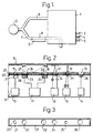
- FIG. 1 shows a ventilator 1 on which a Patient 2 is connected to thus supplied breathing gas to get.
- the gases that together form the breathing gas the fan 1 via gas connections 3, 4 and 5 fed.
- the breathing gas is released over a
- the inspiration line 6 is fed to the patient 2.
- the Exhalation is the breathing gas from patient 2 through a Expiration line 7 and via the ventilator 1 in the Environment, mostly to a collection container, not shown here, guided.
- the expiration line 7 there is a measuring tube 8 arranged with a unit 9, including medical Components.
- FIG. 2 is the measuring tube 8 and the unit 9 in one Comparison to FIG. 1 larger scale shown.
- the medical Components are fixed in the unit 9.
- the unit 9 comprises a pressure sensor 10, an ultrasonic flow meter 11, a carbon dioxide meter 12, an oxygen sensor 13 and a temperature meter 14.
- the components are in a line one after the other arranged.
- Components 10 through 14 are with the interior of the measuring tube 8 through openings 15 to 19 in the wall of the Measuring tube 8 connected.
- the barriers are on a common support 20, e.g.
- the barrier to the pressure transmitter 10 is a Bacteria filter 21, for the ultrasonic flow meter 11 foils 22, which are preferably close to the measuring heads 23 for the carbon dioxide meter 12 a window for the oxygen sensor 13 a transparent film 25 and for the temperature meter 14 a metal foil 26.
- the unit When replacing the carrier 20, the unit is preferably 9 removed from the measuring tube 8. Then the carrier 9 with it Barriers 21, 22, 24, 25, 26 removed from the measuring tube 8 and against replaced a new carrier 20 suitable for the purpose. Then the unit 9 with the medical components 10 to 14 applied again in place.
- the peripheral surface of the carrier 20 is preferably with a seal 27 provided that against an applied carrier 20 against Measuring tube 8 is applied.
- the seal 27 is intended to prevent gas oozed out of the measuring tube.
- sealing rings are also arranged around the openings 15 to 19. In this FIG. only has a sealing ring Reference numeral 28, namely for the opening 15, received.
- FIG. 3 which is a top view of the carrier 20, shows that the barriers 21, 22, 24, 25, 26 in a row one after the other are arranged.
- the seal 27 shown along the peripheral surface of the carrier 20th is arranged.
- the essentials is a replaceable carrier according to the invention with moisture and bacteria barriers to get that way are arranged that each applied to a ventilator Carrier, arranged exactly in front of each component is.
- the barriers can be applied by the carrier preferably between the measuring tube and the unit if necessary attached to the respective medical component become.
- the invention prevents a flow resistance in the ventilator's expiratory flow path.
- Another significant advantage of the invention is that the bearer common for the barriers, the barrier for all medical components in a simple manner at the same time can be exchanged.
Landscapes
- Health & Medical Sciences (AREA)
- General Health & Medical Sciences (AREA)
- Public Health (AREA)
- Engineering & Computer Science (AREA)
- Emergency Medicine (AREA)
- Biomedical Technology (AREA)
- Heart & Thoracic Surgery (AREA)
- Hematology (AREA)
- Life Sciences & Earth Sciences (AREA)
- Pulmonology (AREA)
- Animal Behavior & Ethology (AREA)
- Anesthesiology (AREA)
- Veterinary Medicine (AREA)
- Physics & Mathematics (AREA)
- Electromagnetism (AREA)
- Fluid Mechanics (AREA)
- General Physics & Mathematics (AREA)
- Measurement Of The Respiration, Hearing Ability, Form, And Blood Characteristics Of Living Organisms (AREA)
- Measuring And Recording Apparatus For Diagnosis (AREA)
- Investigating Or Analysing Biological Materials (AREA)
Abstract
Description
- FIG. 1
- ein schematsich gezeichnetes Beatmungsgerät mit einem Meßrohr und einer Einheit für medizinische Komponenten, die im Anschluß an der Exspirationsleitung angeordnet sind,
- FIG. 2
- ein Meßrohr in einem Längsschnitt, eine Einheit mit schematisch gezeichneten medizinischen Komponenten und dazwischen einen Träger für Feuchtigkeits- und Bakterienbarriere nach der Erfindung und
- FIG. 3
- einen Träger nach FIG. 2 in einer Draufsicht.
Claims (6)
- Feuchtigkeits- und Bakterienbarriere (21, 22, 24, 25, 26) für medizinische Komponenten (10 bis 14), die im Anschluß an ein Meßrohr (8), das in den Flußwegen eines Beatmungsgerätes (1) angeordnet ist, angebracht ist, gekennzeichnet durch einen Träger (20), auf dem mindestens zwei Feuchtigkeits- und Bakterienbarrieren (21, 22, 24, 25, 26) derart angebracht sind, daß jeweils eine, bei einem in dem Beatmungsgerät (1) applizierten Träger (20) genau vor jeder Komponente (10 bis 14) angeordnet ist.
- Feuchtigkeits- und Bakterienbarriere nach Anspruch 1, dadurch gekennzeichnet, daß der Träger (20) eine langgestreckte Form aufweist.
- Feuchtigkeits- und Bakterienbarriere nach Anspruch 1 oder 2, dadurch gekennzeichnet, daß die Peripherieoberfläche des Trägers (20) mit einer Dichtung (27) versehen ist, die bei einem applizierten Träger (20) gegen das Meßrohr (8) anliegt.
- Feuchtigkeits- und Bakterienbarriere nach einem der Ansprüche 1 bis 3, dadurch gekennzeichnet, daß die Träger (21, 22, 24, 25, 26) Filter und/oder Membranen sind.
- Beatmungsgerät (1) umfassend ein Meßrohr (8) und eine Einheit (9), in denen fest montierte Komponenten (10 bis 14) angeordnet sind, wobei ein Träger (20) nach einem der Ansprüche 1 bis 4 zwischen dem Meßrohr (8) und der Einheit (9) anbringbar ist.
- Beatmungsgerät nach Anspruch 5, dadurch gekennzeichnet, daß der Träger (20) austauschbar ist.
Applications Claiming Priority (2)
| Application Number | Priority Date | Filing Date | Title |
|---|---|---|---|
| SE9803047A SE9803047D0 (sv) | 1998-09-09 | 1998-09-09 | Fukt- och bakteriebarriär för medicinska komponenter |
| SE9803047 | 1998-09-09 |
Publications (3)
| Publication Number | Publication Date |
|---|---|
| EP0985422A2 true EP0985422A2 (de) | 2000-03-15 |
| EP0985422A3 EP0985422A3 (de) | 2000-12-06 |
| EP0985422B1 EP0985422B1 (de) | 2007-08-01 |
Family
ID=20412531
Family Applications (1)
| Application Number | Title | Priority Date | Filing Date |
|---|---|---|---|
| EP99116227A Expired - Lifetime EP0985422B1 (de) | 1998-09-09 | 1999-08-17 | Feuchtigkeits- und Bakterienbarriere für medizinische Komponenten |
Country Status (5)
| Country | Link |
|---|---|
| US (1) | US6397846B1 (de) |
| EP (1) | EP0985422B1 (de) |
| JP (1) | JP4194720B2 (de) |
| DE (1) | DE59914430D1 (de) |
| SE (1) | SE9803047D0 (de) |
Cited By (2)
| Publication number | Priority date | Publication date | Assignee | Title |
|---|---|---|---|---|
| EP1138341A3 (de) * | 2000-03-21 | 2003-08-13 | FISHER & PAYKEL LIMITED | Befeuchtungsvorrichtung |
| EP1279368A3 (de) * | 2001-07-17 | 2004-09-15 | ndd Medizintechnik AG | Vorrichtung zur Messung der Strömungsgeschwindigkeit und/oder der Molmasse von Gasen- oder Gasgemischen |
Families Citing this family (22)
| Publication number | Priority date | Publication date | Assignee | Title |
|---|---|---|---|---|
| US7640932B2 (en) * | 1997-04-29 | 2010-01-05 | Salter Labs | Nasal cannula for acquiring breathing information |
| US7111624B2 (en) | 2000-03-21 | 2006-09-26 | Fisher & Paykel Healthcare Limited | Apparatus for delivering humidified gases |
| US7120354B2 (en) | 2000-03-21 | 2006-10-10 | Fisher & Paykel Healthcare Limited | Gases delivery conduit |
| US7588029B2 (en) | 2000-03-21 | 2009-09-15 | Fisher & Paykel Healthcare Limited | Humidified gases delivery apparatus |
| CA2424647C (en) | 2000-10-16 | 2009-09-08 | Fisher & Paykel Healthcare Limited | Improvements to apparatus used for the humidification of gases in medical procedures |
| US20030075049A1 (en) * | 2001-10-19 | 2003-04-24 | Larsen Michael T. | Gas/liquid separator including a liquid trap filter |
| CN103143099B (zh) | 2004-08-20 | 2018-04-20 | 菲舍尔和佩克尔保健有限公司 | 用于测量供应给患者的气体的特性的装置 |
| US8757150B2 (en) * | 2004-12-17 | 2014-06-24 | Ric Investments, Llc | Condensation reduction and management systems in a gas flow delivery system |
| US7992561B2 (en) * | 2006-09-25 | 2011-08-09 | Nellcor Puritan Bennett Llc | Carbon dioxide-sensing airway products and technique for using the same |
| GB2468522B (en) * | 2009-03-12 | 2013-08-07 | Autoliv Dev | A breath analyser |
| JP5852587B2 (ja) | 2010-02-22 | 2016-02-03 | クリティケア システムズ インコーポレイテッドCriticare Systems, Inc. | インライン式水分除去装置 |
| US8752544B2 (en) * | 2011-03-21 | 2014-06-17 | General Electric Company | Medical vaporizer and method of monitoring of a medical vaporizer |
| CA3177636A1 (en) | 2011-06-03 | 2012-12-06 | Fisher & Paykel Healthcare Limited | Medical tubes and methods of manufacture |
| CA2871850A1 (en) | 2012-05-23 | 2013-11-28 | Fisher & Paykel Healthcare Limited | Flow path fault detection method for a respiratory assistance apparatus |
| CN104955510B (zh) | 2012-11-14 | 2017-05-10 | 费雪派克医疗保健有限公司 | 用于呼吸回路的分区加热 |
| JP6412879B2 (ja) | 2012-12-04 | 2018-10-24 | フィッシャー アンド ペイケル ヘルスケア リミテッド | 医療用チューブおよびその製造方法 |
| RU2544944C2 (ru) * | 2013-02-26 | 2015-03-20 | Закрытое акционерное общество "ПРОММАШСЕРВИС" | Способ удаления песчано-глинистой пробки в скважине и ее освоение в условиях аномально низких пластовых давлений |
| US10814091B2 (en) | 2013-10-24 | 2020-10-27 | Fisher & Paykel Healthcare Limited | System for delivery of respiratory gases |
| GB2558102B (en) | 2013-12-20 | 2018-11-28 | Fisher & Paykel Healthcare Ltd | Humidification system connections |
| CN111265754B (zh) | 2014-03-17 | 2023-06-06 | 费雪派克医疗保健有限公司 | 用于呼吸系统的医用管 |
| JP7014717B2 (ja) | 2015-09-09 | 2022-02-01 | フィッシャー アンド ペイケル ヘルスケア リミテッド | 呼吸回路用の区域加熱 |
| US11311695B2 (en) | 2016-12-22 | 2022-04-26 | Fisher & Paykel Healthcare Limited | Medical tubes and methods of manufacture |
Citations (2)
| Publication number | Priority date | Publication date | Assignee | Title |
|---|---|---|---|---|
| US5419326A (en) | 1992-06-03 | 1995-05-30 | Ndd Medizintechnik Gmbh | Spirometer, more particularly an ultrasonic spirometer |
| EP0841083A1 (de) | 1996-10-03 | 1998-05-13 | Siemens-Elema AB | Verfahren und Vorrichtung zur Prüfung von der Zustand eines Filters in einem Beatmungsgerät |
Family Cites Families (9)
| Publication number | Priority date | Publication date | Assignee | Title |
|---|---|---|---|---|
| US923776A (en) * | 1909-01-04 | 1909-06-01 | Samuel Danielewicz | Filtrative inhaler. |
| US4558708A (en) * | 1984-10-24 | 1985-12-17 | Tri-Med, Inc. | Patient's airway adapter to withdraw a patient's gas samples for testing free of sputum mucus and/or condensed water, by utilizing a hollow cylindrical hydrophobic liquid baffle |
| IL76939A (en) * | 1984-11-13 | 1990-01-18 | Andros Analyzers Inc | Adaptor assembly for airway tube |
| US5289255A (en) * | 1991-03-28 | 1994-02-22 | Minnesota Mining And Manufacturing Co. | Cuvette for use in making a measurement of a blood parameter and assembly utilizing the same |
| WO1993025142A2 (en) * | 1992-06-16 | 1993-12-23 | Natus Medical, Inc. | In vivo measurement of end-tidal carbon monoxide concentration apparatus and methods and filters therefor |
| US5293875A (en) * | 1992-06-16 | 1994-03-15 | Natus Medical Incorporated | In-vivo measurement of end-tidal carbon monoxide concentration apparatus and methods |
| US5361771A (en) * | 1993-03-05 | 1994-11-08 | Western Research Company, Inc. | Portable pulmonary function testing device and method |
| DE9410661U1 (de) | 1994-07-01 | 1994-10-13 | NDD Medizintechnik GmbH, 97074 Würzburg | Ultraschall-Spirometer |
| US5789660A (en) * | 1996-07-15 | 1998-08-04 | Novametrix Medical Systems, Inc. | Multiple function airway adapter |
-
1998
- 1998-09-09 SE SE9803047A patent/SE9803047D0/xx unknown
-
1999
- 1999-08-17 EP EP99116227A patent/EP0985422B1/de not_active Expired - Lifetime
- 1999-08-17 DE DE59914430T patent/DE59914430D1/de not_active Expired - Lifetime
- 1999-08-25 US US09/382,337 patent/US6397846B1/en not_active Expired - Lifetime
- 1999-09-06 JP JP25198899A patent/JP4194720B2/ja not_active Expired - Fee Related
Patent Citations (2)
| Publication number | Priority date | Publication date | Assignee | Title |
|---|---|---|---|---|
| US5419326A (en) | 1992-06-03 | 1995-05-30 | Ndd Medizintechnik Gmbh | Spirometer, more particularly an ultrasonic spirometer |
| EP0841083A1 (de) | 1996-10-03 | 1998-05-13 | Siemens-Elema AB | Verfahren und Vorrichtung zur Prüfung von der Zustand eines Filters in einem Beatmungsgerät |
Cited By (2)
| Publication number | Priority date | Publication date | Assignee | Title |
|---|---|---|---|---|
| EP1138341A3 (de) * | 2000-03-21 | 2003-08-13 | FISHER & PAYKEL LIMITED | Befeuchtungsvorrichtung |
| EP1279368A3 (de) * | 2001-07-17 | 2004-09-15 | ndd Medizintechnik AG | Vorrichtung zur Messung der Strömungsgeschwindigkeit und/oder der Molmasse von Gasen- oder Gasgemischen |
Also Published As
| Publication number | Publication date |
|---|---|
| JP2000084080A (ja) | 2000-03-28 |
| EP0985422A3 (de) | 2000-12-06 |
| DE59914430D1 (de) | 2007-09-13 |
| SE9803047D0 (sv) | 1998-09-09 |
| JP4194720B2 (ja) | 2008-12-10 |
| US6397846B1 (en) | 2002-06-04 |
| EP0985422B1 (de) | 2007-08-01 |
Similar Documents
| Publication | Publication Date | Title |
|---|---|---|
| EP0985422B1 (de) | Feuchtigkeits- und Bakterienbarriere für medizinische Komponenten | |
| WO1993024810A1 (de) | Spirometer, insbesondere ultraschall-spirometer | |
| DE69729430T2 (de) | Endotracheales Drucküberwachungs- und Medikationssystem | |
| DE602004013263T2 (de) | Sensorschutzvorrichtung mit Doppelmembran | |
| DE2847681C2 (de) | Trachealtubus | |
| DE69837926T2 (de) | Umhüllter filter für einen beatmungskreislauf | |
| DE2331687C3 (de) | Für medizinische Geräte geeignete Kupplung | |
| DE69120734T2 (de) | Y-förmiges Verbindungsstück für Beatmungsgerät | |
| DE69432862T2 (de) | Respirationsanzeige mit vereinfachtem atem-sensor | |
| EP1279368A2 (de) | Vorrichtung zur Messung der Strömungsgeschwindigkeit und/oder der Molmasse von Gasen- oder Gasgemischen | |
| DE3836590A1 (de) | Vorrichtung zur stoma-versorgung | |
| DE69521026T2 (de) | Vorrichtung zur messung der maximalströmung der ausatemluft | |
| DE2121740A1 (de) | Druckwandler | |
| WO2008052765A2 (de) | Katheter | |
| EP0945712A1 (de) | Vorrichtung zum Messen eines Gasflusses | |
| EP4007628B1 (de) | Bidirektional durchströmbare atemgas-ventilbaugruppe und beatmungsvorrichtung mit einer solchen | |
| DE102007006732A1 (de) | Atemschutzmaske mit Mikrofon | |
| WO2003063937A1 (de) | Atemflussmessvorrichtung | |
| DE102012002632B4 (de) | Beatmungssystem und Konnektorsystem hierfür zur Verminderung von Kontaminationen | |
| DE102018113154A1 (de) | Endotrachealtubusadapter | |
| EP3484562A1 (de) | Verneblereinheit mit wechselbarem mundstück | |
| DE8511214U1 (de) | Vorrichtung zur Inhalation von Allergenen | |
| DE9317549U1 (de) | System mit Zahnbohrhandstück mit Dichtelement | |
| EP0616792A1 (de) | Referenzimpedanz für die Kalibration der Druck- und Flowmesseinrichtung eines Gerätes zur oszillometrischen Messung des Atemwegwiderstands | |
| EP0340774A2 (de) | Verfahren und Vorrichtung zur Messung elektrodermaler Reaktionen |
Legal Events
| Date | Code | Title | Description |
|---|---|---|---|
| PUAI | Public reference made under article 153(3) epc to a published international application that has entered the european phase |
Free format text: ORIGINAL CODE: 0009012 |
|
| AK | Designated contracting states |
Kind code of ref document: A2 Designated state(s): DE FR |
|
| AX | Request for extension of the european patent |
Free format text: AL;LT;LV;MK;RO;SI |
|
| PUAL | Search report despatched |
Free format text: ORIGINAL CODE: 0009013 |
|
| AK | Designated contracting states |
Kind code of ref document: A3 Designated state(s): AT BE CH CY DE DK ES FI FR GB GR IE IT LI LU MC NL PT SE |
|
| AX | Request for extension of the european patent |
Free format text: AL;LT;LV;MK;RO;SI |
|
| RIC1 | Information provided on ipc code assigned before grant |
Free format text: 7A 61M 16/08 A |
|
| 17P | Request for examination filed |
Effective date: 20010605 |
|
| AKX | Designation fees paid |
Free format text: DE FR |
|
| RAP1 | Party data changed (applicant data changed or rights of an application transferred) |
Owner name: MAQUET CRITICAL CARE AB |
|
| 17Q | First examination report despatched |
Effective date: 20050630 |
|
| GRAP | Despatch of communication of intention to grant a patent |
Free format text: ORIGINAL CODE: EPIDOSNIGR1 |
|
| GRAJ | Information related to disapproval of communication of intention to grant by the applicant or resumption of examination proceedings by the epo deleted |
Free format text: ORIGINAL CODE: EPIDOSDIGR1 |
|
| 17Q | First examination report despatched |
Effective date: 20050630 |
|
| GRAP | Despatch of communication of intention to grant a patent |
Free format text: ORIGINAL CODE: EPIDOSNIGR1 |
|
| GRAS | Grant fee paid |
Free format text: ORIGINAL CODE: EPIDOSNIGR3 |
|
| GRAA | (expected) grant |
Free format text: ORIGINAL CODE: 0009210 |
|
| AK | Designated contracting states |
Kind code of ref document: B1 Designated state(s): DE FR |
|
| REF | Corresponds to: |
Ref document number: 59914430 Country of ref document: DE Date of ref document: 20070913 Kind code of ref document: P |
|
| ET | Fr: translation filed | ||
| PLBE | No opposition filed within time limit |
Free format text: ORIGINAL CODE: 0009261 |
|
| STAA | Information on the status of an ep patent application or granted ep patent |
Free format text: STATUS: NO OPPOSITION FILED WITHIN TIME LIMIT |
|
| 26N | No opposition filed |
Effective date: 20080506 |
|
| REG | Reference to a national code |
Ref country code: DE Ref legal event code: R082 Ref document number: 59914430 Country of ref document: DE Representative=s name: SCHAUMBURG UND PARTNER PATENTANWAELTE MBB, DE Ref country code: DE Ref legal event code: R082 Ref document number: 59914430 Country of ref document: DE Representative=s name: SCHAUMBURG & PARTNER PATENTANWAELTE GBR, DE |
|
| REG | Reference to a national code |
Ref country code: FR Ref legal event code: PLFP Year of fee payment: 17 |
|
| PGFP | Annual fee paid to national office [announced via postgrant information from national office to epo] |
Ref country code: DE Payment date: 20150811 Year of fee payment: 17 |
|
| PGFP | Annual fee paid to national office [announced via postgrant information from national office to epo] |
Ref country code: FR Payment date: 20150629 Year of fee payment: 17 |
|
| REG | Reference to a national code |
Ref country code: DE Ref legal event code: R119 Ref document number: 59914430 Country of ref document: DE |
|
| REG | Reference to a national code |
Ref country code: FR Ref legal event code: ST Effective date: 20170428 |
|
| PG25 | Lapsed in a contracting state [announced via postgrant information from national office to epo] |
Ref country code: FR Free format text: LAPSE BECAUSE OF NON-PAYMENT OF DUE FEES Effective date: 20160831 Ref country code: DE Free format text: LAPSE BECAUSE OF NON-PAYMENT OF DUE FEES Effective date: 20170301 |