EP0985454A2 - Spender für Medien - Google Patents
Spender für Medien Download PDFInfo
- Publication number
- EP0985454A2 EP0985454A2 EP99117184A EP99117184A EP0985454A2 EP 0985454 A2 EP0985454 A2 EP 0985454A2 EP 99117184 A EP99117184 A EP 99117184A EP 99117184 A EP99117184 A EP 99117184A EP 0985454 A2 EP0985454 A2 EP 0985454A2
- Authority
- EP
- European Patent Office
- Prior art keywords
- valve
- outlet
- media
- valve body
- chamber
- Prior art date
- Legal status (The legal status is an assumption and is not a legal conclusion. Google has not performed a legal analysis and makes no representation as to the accuracy of the status listed.)
- Granted
Links
- 239000012530 fluid Substances 0.000 title description 2
- 238000011144 upstream manufacturing Methods 0.000 claims description 28
- 238000007789 sealing Methods 0.000 claims description 6
- 238000009423 ventilation Methods 0.000 claims description 6
- 230000009969 flowable effect Effects 0.000 claims description 2
- 238000004659 sterilization and disinfection Methods 0.000 claims 1
- 230000015572 biosynthetic process Effects 0.000 abstract 1
- 210000003128 head Anatomy 0.000 description 12
- 230000001914 calming effect Effects 0.000 description 6
- 238000013459 approach Methods 0.000 description 5
- 238000012549 training Methods 0.000 description 5
- 230000001154 acute effect Effects 0.000 description 4
- 244000052616 bacterial pathogen Species 0.000 description 4
- 230000007704 transition Effects 0.000 description 4
- 230000006835 compression Effects 0.000 description 3
- 238000007906 compression Methods 0.000 description 3
- 238000001035 drying Methods 0.000 description 3
- 239000000853 adhesive Substances 0.000 description 2
- 230000001070 adhesive effect Effects 0.000 description 2
- 230000002906 microbiologic effect Effects 0.000 description 2
- 238000007639 printing Methods 0.000 description 2
- 238000012546 transfer Methods 0.000 description 2
- 210000001015 abdomen Anatomy 0.000 description 1
- 230000006399 behavior Effects 0.000 description 1
- 238000005452 bending Methods 0.000 description 1
- 230000009286 beneficial effect Effects 0.000 description 1
- 230000005540 biological transmission Effects 0.000 description 1
- 210000005252 bulbus oculi Anatomy 0.000 description 1
- 239000003795 chemical substances by application Substances 0.000 description 1
- 230000009194 climbing Effects 0.000 description 1
- 230000000295 complement effect Effects 0.000 description 1
- 238000010276 construction Methods 0.000 description 1
- 238000011109 contamination Methods 0.000 description 1
- 230000006735 deficit Effects 0.000 description 1
- 238000006073 displacement reaction Methods 0.000 description 1
- 210000001508 eye Anatomy 0.000 description 1
- 210000000887 face Anatomy 0.000 description 1
- 239000011521 glass Substances 0.000 description 1
- 230000005484 gravity Effects 0.000 description 1
- 230000008595 infiltration Effects 0.000 description 1
- 238000001764 infiltration Methods 0.000 description 1
- 238000002347 injection Methods 0.000 description 1
- 239000007924 injection Substances 0.000 description 1
- 238000001746 injection moulding Methods 0.000 description 1
- 239000007788 liquid Substances 0.000 description 1
- 239000002184 metal Substances 0.000 description 1
- 238000000034 method Methods 0.000 description 1
- 235000011837 pasties Nutrition 0.000 description 1
- 230000037452 priming Effects 0.000 description 1
- 230000001681 protective effect Effects 0.000 description 1
- 238000005086 pumping Methods 0.000 description 1
- 210000002435 tendon Anatomy 0.000 description 1
Images

Classifications
-
- B—PERFORMING OPERATIONS; TRANSPORTING
- B65—CONVEYING; PACKING; STORING; HANDLING THIN OR FILAMENTARY MATERIAL
- B65D—CONTAINERS FOR STORAGE OR TRANSPORT OF ARTICLES OR MATERIALS, e.g. BAGS, BARRELS, BOTTLES, BOXES, CANS, CARTONS, CRATES, DRUMS, JARS, TANKS, HOPPERS, FORWARDING CONTAINERS; ACCESSORIES, CLOSURES, OR FITTINGS THEREFOR; PACKAGING ELEMENTS; PACKAGES
- B65D47/00—Closures with filling and discharging, or with discharging, devices
- B65D47/04—Closures with discharging devices other than pumps
- B65D47/20—Closures with discharging devices other than pumps comprising hand-operated members for controlling discharge
- B65D47/2018—Closures with discharging devices other than pumps comprising hand-operated members for controlling discharge comprising a valve or like element which is opened or closed by deformation of the container or closure
- B65D47/2056—Closures with discharging devices other than pumps comprising hand-operated members for controlling discharge comprising a valve or like element which is opened or closed by deformation of the container or closure lift valve type
- B65D47/2062—Closures with discharging devices other than pumps comprising hand-operated members for controlling discharge comprising a valve or like element which is opened or closed by deformation of the container or closure lift valve type in which the deformation raises or lowers the valve stem
- B65D47/2075—Closures with discharging devices other than pumps comprising hand-operated members for controlling discharge comprising a valve or like element which is opened or closed by deformation of the container or closure lift valve type in which the deformation raises or lowers the valve stem in which the stem is raised by the pressure of the contents and thereby opening the valve
-
- B—PERFORMING OPERATIONS; TRANSPORTING
- B05—SPRAYING OR ATOMISING IN GENERAL; APPLYING FLUENT MATERIALS TO SURFACES, IN GENERAL
- B05B—SPRAYING APPARATUS; ATOMISING APPARATUS; NOZZLES
- B05B11/00—Single-unit hand-held apparatus in which flow of contents is produced by the muscular force of the operator at the moment of use
- B05B11/0005—Components or details
- B05B11/0037—Containers
- B05B11/0039—Containers associated with means for compensating the pressure difference between the ambient pressure and the pressure inside the container, e.g. pressure relief means
- B05B11/0044—Containers associated with means for compensating the pressure difference between the ambient pressure and the pressure inside the container, e.g. pressure relief means compensating underpressure by ingress of atmospheric air into the container, i.e. with venting means
- B05B11/00444—Containers associated with means for compensating the pressure difference between the ambient pressure and the pressure inside the container, e.g. pressure relief means compensating underpressure by ingress of atmospheric air into the container, i.e. with venting means with provision for filtering or cleaning the air flow drawn into the container
-
- B—PERFORMING OPERATIONS; TRANSPORTING
- B05—SPRAYING OR ATOMISING IN GENERAL; APPLYING FLUENT MATERIALS TO SURFACES, IN GENERAL
- B05B—SPRAYING APPARATUS; ATOMISING APPARATUS; NOZZLES
- B05B11/00—Single-unit hand-held apparatus in which flow of contents is produced by the muscular force of the operator at the moment of use
- B05B11/0005—Components or details
- B05B11/0059—Components or details allowing operation in any orientation, e.g. for discharge in inverted position
-
- B—PERFORMING OPERATIONS; TRANSPORTING
- B05—SPRAYING OR ATOMISING IN GENERAL; APPLYING FLUENT MATERIALS TO SURFACES, IN GENERAL
- B05B—SPRAYING APPARATUS; ATOMISING APPARATUS; NOZZLES
- B05B11/00—Single-unit hand-held apparatus in which flow of contents is produced by the muscular force of the operator at the moment of use
- B05B11/0005—Components or details
- B05B11/0062—Outlet valves actuated by the pressure of the fluid to be sprayed
- B05B11/0064—Lift valves
-
- B—PERFORMING OPERATIONS; TRANSPORTING
- B05—SPRAYING OR ATOMISING IN GENERAL; APPLYING FLUENT MATERIALS TO SURFACES, IN GENERAL
- B05B—SPRAYING APPARATUS; ATOMISING APPARATUS; NOZZLES
- B05B11/00—Single-unit hand-held apparatus in which flow of contents is produced by the muscular force of the operator at the moment of use
- B05B11/0005—Components or details
- B05B11/0062—Outlet valves actuated by the pressure of the fluid to be sprayed
- B05B11/0072—A valve member forming part of an outlet opening
-
- B—PERFORMING OPERATIONS; TRANSPORTING
- B05—SPRAYING OR ATOMISING IN GENERAL; APPLYING FLUENT MATERIALS TO SURFACES, IN GENERAL
- B05B—SPRAYING APPARATUS; ATOMISING APPARATUS; NOZZLES
- B05B11/00—Single-unit hand-held apparatus in which flow of contents is produced by the muscular force of the operator at the moment of use
- B05B11/0005—Components or details
- B05B11/0062—Outlet valves actuated by the pressure of the fluid to be sprayed
- B05B11/0075—Two outlet valves being placed in a delivery conduit, one downstream the other
-
- B—PERFORMING OPERATIONS; TRANSPORTING
- B05—SPRAYING OR ATOMISING IN GENERAL; APPLYING FLUENT MATERIALS TO SURFACES, IN GENERAL
- B05B—SPRAYING APPARATUS; ATOMISING APPARATUS; NOZZLES
- B05B11/00—Single-unit hand-held apparatus in which flow of contents is produced by the muscular force of the operator at the moment of use
- B05B11/01—Single-unit hand-held apparatus in which flow of contents is produced by the muscular force of the operator at the moment of use characterised by the means producing the flow
- B05B11/10—Pump arrangements for transferring the contents from the container to a pump chamber by a sucking effect and forcing the contents out through the dispensing nozzle
- B05B11/1001—Piston pumps
- B05B11/1004—Piston pumps comprising a movable cylinder and a stationary piston
-
- B—PERFORMING OPERATIONS; TRANSPORTING
- B05—SPRAYING OR ATOMISING IN GENERAL; APPLYING FLUENT MATERIALS TO SURFACES, IN GENERAL
- B05B—SPRAYING APPARATUS; ATOMISING APPARATUS; NOZZLES
- B05B11/00—Single-unit hand-held apparatus in which flow of contents is produced by the muscular force of the operator at the moment of use
- B05B11/01—Single-unit hand-held apparatus in which flow of contents is produced by the muscular force of the operator at the moment of use characterised by the means producing the flow
- B05B11/10—Pump arrangements for transferring the contents from the container to a pump chamber by a sucking effect and forcing the contents out through the dispensing nozzle
- B05B11/1001—Piston pumps
- B05B11/1023—Piston pumps having an outlet valve opened by deformation or displacement of the piston relative to its actuating stem
- B05B11/1026—Piston pumps having an outlet valve opened by deformation or displacement of the piston relative to its actuating stem the piston being deformable and its deformation allowing opening of the outlet
-
- B—PERFORMING OPERATIONS; TRANSPORTING
- B05—SPRAYING OR ATOMISING IN GENERAL; APPLYING FLUENT MATERIALS TO SURFACES, IN GENERAL
- B05B—SPRAYING APPARATUS; ATOMISING APPARATUS; NOZZLES
- B05B11/00—Single-unit hand-held apparatus in which flow of contents is produced by the muscular force of the operator at the moment of use
- B05B11/01—Single-unit hand-held apparatus in which flow of contents is produced by the muscular force of the operator at the moment of use characterised by the means producing the flow
- B05B11/10—Pump arrangements for transferring the contents from the container to a pump chamber by a sucking effect and forcing the contents out through the dispensing nozzle
- B05B11/1042—Components or details
- B05B11/1052—Actuation means
- B05B11/1053—Actuation means combined with means, other than pressure, for automatically opening a valve during actuation; combined with means for automatically removing closures or covers from the discharge nozzle during actuation
-
- B—PERFORMING OPERATIONS; TRANSPORTING
- B05—SPRAYING OR ATOMISING IN GENERAL; APPLYING FLUENT MATERIALS TO SURFACES, IN GENERAL
- B05B—SPRAYING APPARATUS; ATOMISING APPARATUS; NOZZLES
- B05B11/00—Single-unit hand-held apparatus in which flow of contents is produced by the muscular force of the operator at the moment of use
- B05B11/01—Single-unit hand-held apparatus in which flow of contents is produced by the muscular force of the operator at the moment of use characterised by the means producing the flow
- B05B11/10—Pump arrangements for transferring the contents from the container to a pump chamber by a sucking effect and forcing the contents out through the dispensing nozzle
- B05B11/1042—Components or details
- B05B11/1066—Pump inlet valves
- B05B11/107—Gate valves; Sliding valves
-
- B—PERFORMING OPERATIONS; TRANSPORTING
- B05—SPRAYING OR ATOMISING IN GENERAL; APPLYING FLUENT MATERIALS TO SURFACES, IN GENERAL
- B05B—SPRAYING APPARATUS; ATOMISING APPARATUS; NOZZLES
- B05B11/00—Single-unit hand-held apparatus in which flow of contents is produced by the muscular force of the operator at the moment of use
- B05B11/01—Single-unit hand-held apparatus in which flow of contents is produced by the muscular force of the operator at the moment of use characterised by the means producing the flow
- B05B11/10—Pump arrangements for transferring the contents from the container to a pump chamber by a sucking effect and forcing the contents out through the dispensing nozzle
- B05B11/1042—Components or details
- B05B11/1073—Springs
- B05B11/1074—Springs located outside pump chambers
Definitions
- the invention relates to a dispenser with which e.g. flowable Media released or discharged under pressure can. It is especially liquid media, but also pasty, powdery and / or gaseous media suitable.
- the dispenser should be portable with one hand and simultaneously be operable for the discharge. He or most its parts should consist of injection molding or plastic.
- the medium can be finely atomized, however, the donor is intended in particular to dispense individuals Media clusters or drops should be suitable. You have at least 5 or 15 and maximum 40 or 25 ⁇ l volume and contain medicinal agents for the treatment of the eyes or the like
- the donor should be microbiologically as dense as possible contamination of the stored medium from the outside avoid.
- the medium should be primed before first use. of the donor during the longest possible storage period, however even after the first media release against such impairments be protected.
- the donor can be for a single Discharge of a media dose or be trained that the discharge operation until it is completely emptied is only moved in one direction. There is no return or Intake stroke required.
- the entire media stock can be without additional media storage right from the start in a delivery chamber be included to promote the pressure of the medium is variable in volume.
- the donor or the discharge can also work reversibly, namely repeatedly over one working stroke to promote pressure and one immediately Subsequent return stroke to suck in another media dose into the delivery chamber. After discharge of the media dose the microbiological seal should last until the next discharge always be restored, what with a disposable donor is not always required.
- sealing is a single valve or are suitable for several valves. Their closing gaps are in Direction of flow in succession in the outlet channel. That downstream last valve is as close as possible to the media outlet or at the opening limitation of this outlet, the through the transition between an inner circumference and one this transverse end surface is formed. At this The transition separates the medium from all inner circumferences or Inner surfaces of the dispenser face outside, but can be downstream of which still directed to the outside surfaces of the dispenser become.
- the invention has for its object to a donor create the disadvantages of known training avoided or beneficial effects of the type mentioned are achieved.
- the donor should have a repeated one microbiological sealing against ingress of germs the opening limitation of the media outlet or inflow openings guarantee.
- the dispenser should be easy to use or be under construction.
- the donor is supposed to Assembling modules to be suitable for media to be able to be adapted to different flow behavior.
- the dispenser has a high surface pressure closing valve.
- the closing gap can also form the mentioned opening limitation of the media outlet.
- the closing gap reaches the most possible Location of the outlet channel at which the medium is discharged is replaced. This point is when the valve is closed microbiologically tight. Germs can therefore at most the outside of the dispenser, which is always freely accessible, but not upstream through the dense closing gap penetrate inside dispenser surfaces.
- the closing force is only useful when there is media pressure reduced in the outlet duct, which is at least 0.7 or 1 or 1.4 bar.
- the valve could be operated purely mechanically open regardless of media printing. It will however conveniently opened by fluid control when the Media printing has reached the specified value.
- the said Tightness and preventing the infiltration of germs The valve can also be opened through the smallest possible valve paths be improved.
- the maximum relative valve travel of the both valve bodies for opening or closing is under 2 mm, 1 mm, 0.7 mm or 0.4 mm., E.g. at 0.3 mm.
- When dropping the medium then occurs almost without pressure or capillary creeping out through the valve gap.
- Upstream the higher media pressure mentioned keeps the valve open.
- the exiting and the opening communicate Media shares in the outlet channel. Even further upstream can use means, such as a pump, to produce another higher or two to five times higher media pressure provided his. It is e.g. at least 4, 6 or 7 bar.
- the valve allows the valve to be kept open.
- the delivery chamber has a much lower pressure for example, at most or less than two or one generated bar, it is advantageous to open the end valve between the delivery chamber and the control member to open the End valve provided a power transmission.
- the Opening pressure on correspondingly large areas of the control element. Possibly. are areas on which the media print in the closing direction in contrast, looks much smaller.
- the discharge of the medium can be reached at the media outlet downstream of the media portions opening the valve Throttle gap provided.
- Whose passage cross section is much smaller than that of the open valve and can be variable depending on the media pressure.
- the open passage cross section of the valve is at least 2-, 40 or 50 times larger than the throttle cross-section.
- Another valve can be provided upstream of the end valve his. It has the characteristics of the choke. Also this valve closes microbiologically tight, e.g. upstream immediately adjacent to the media outlet by radial pressure.
- the closing surfaces of the throttle valve are in the Area of the nozzle channel forming the media outlet or in this. One of these closing surfaces can be made in one piece with a the closing surfaces of the closing gap at the media outlet. This allows the same valve body to open one Valves movable closing surface and one for opening the other valves, e.g. with the end valve open, fixed Form the closing surface for the throttle valve.
- Upstream of the above valves is in the exhaust port at least one further throttle or valve intended. E.g. becomes the media portion used to open the valve when continuing to flow towards the throttle or end valve already throttled in constant throttle cross-sections.
- the medium is also at the transfer from the delivery chamber throttled in the outlet channel or at this transition microbiologically sealed.
- a spring loaded Outlet or pressure relief valve suitable.
- the closing surfaces of each of the valves only line contact or maximum closing pressure along one, e.g. have an annular line. Work through it maximum specific surface pressures.
- One of the closing areas is therefore in each case as a sharp edge of two at an angle contiguous flanks or limited by a spherical surface formed.
- the medium is pumped through a piston pump or a flexible squeeze container, such as a tube, conveyed manually.
- a piston pump or a flexible squeeze container such as a tube
- the entire valve control is the dispenser arranged in the narrowed tube tip, which is in one piece with the tube jacket is formed.
- a drop former intended. With it, the medium, in particular if the dispenser is held upside down Media outlet, to an exposed drop of a metered Volume collected. The drop then adheres with it a smaller diameter than its largest diameter so on the donor that it only comes off when its lower end surface in contact with a counter surface, e.g. the eyeball comes. With this touch the begins Overflowing drops on the counter surface.
- the drop collector or drop former expediently has a convex and / or concave adhesive surface for the drop. It can be spherical or smooth or to enlarge their surface at the same Base area to be polygonal. It connects immediately the closing surfaces of the end valve. It is through that End of a mandrel passing through the media outlet.
- the dispenser 1 has two units 2, 3 with one-piece Basic bodies 4, 5. Their mutual displacement leads to shorten and lengthen the dispenser 1.
- the supporting body 5 is one with a flange 7 close to the narrowed neck Memory 6, e.g. a bottle made of glass or the like.
- the units 2, 4 and 3, 5 form a pump 9 or a piston pump with a manual discharge control. All parts lie in axis 10.
- the medium flows during discharge parallel to axis 10 in direction 11 from unit 3 the unit 2 from its media outlet 13.
- the Unit 2 in the opposite direction 12 with the outlet 13 shifted to unit 3.
- the outlet 13 can be perpendicular to the axis 10. He is by the end of only one unit 2 Outlet channel 14 formed. Whose upstream end is directly connected to a delivery chamber 15. She is of both bodies 4, 5 limited in volume. Upstream the chamber 15 closes valve-free to a preliminary or Pre-suction chamber 16. It becomes valve-free via a riser 17 supplied with medium from the bottom of the memory 6. According to its emptying flows into the storage every working stroke from outside atmospheric air via a Ventilation 18 after. It is delimited by both bodies 4, 5. The return stroke of the units 2, 3 to the longer starting position the dispenser 1 is driven by a spring 19. It is as permanently pre-tensioned helical compression spring on both bodies 4, 5 supported directly.
- valves 20 to 23 When flowing from the chamber 15 to from the outlet 13 that is Medium successively and separately from valves 20 to 23 controlled. They are in this number and order from the area of the outlet 13 upstream to the end of the Chamber 15. They each form a separate longitudinal section of the channel 14.
- the ventilation 18 is via a valve 24 controlled.
- the valve 20 has two separate one inside the other lying, one-piece valve body 25, 26. Seine Closing surfaces 27, 28 limit the outlet 13 the medium from the donor 1 to the outside or it is only liable still on a one-piece, freely accessible outer surface of the Dispensers 1.
- the outer, ring-shaped and towards 11 flared closing surface 28 forms the end of a one-piece limited nozzle bore 29 of the unit 2.
- Die inner, complementary annular or conical closing surface 27 is formed by the pin-shaped body 25. He will with a control 30 for valve opening in the direction 11 moves when a correspondingly high media pressure in the chamber 15 is reached, the valve 23 has opened and the pressure the downstream region of the channel 14 reached.
- the controller 30 has a piston 31 in the direction 12 flared piston lip, which from a piston crown stands freely. That is upstream in the piston crown Anchored at the end of the body 25. Channel 14 and enforce the rotationally symmetrical shaft 33 of the body 25 the piston crown and limit the channel 14 together here.
- the shaft has at the downstream end of the body 25 33 an enlarged head 32. It forms after the Outer circumference of the shaft 33, the closing surface 27. Zur The closed position is the body 25 with a permanently biased Spring 34 loaded. It closes immediately downstream to the piston crown and surrounds only the shaft 33 as Helical compression spring inside the channel 14. In the starting position is the body 25 with an annular disc Stop 35 set. The end of the piston lip lies on it 31 on and with its inner circumference, it delimits the channel 14.
- the cap-shaped valve body 26 has one opposite its outer diameter up to twice the jacket 36 on. It merges in one piece into an end wall 37. It is from Channel 29 and the opening 13 penetrated. In the upstream stepped widened end of the jacket 36 engages 11, a sleeve-shaped extension 38 of the body 4. Between its end face and an annular inner shoulder the stop 35 is fixed. The coat 36 extends to to a handle 39 of the actuation 8.
- the body 26 of the unit 2 forms in or parallel to Axis 10 a nozzle-shaped discharge head 40. It is in Direction 11 tapers steadily towards its end and also towards Introduction into a body, such as a nostril, suitable.
- the inner circumference of the jacket 36 forms up to the stop 35 a sealing tread 41 for the piston 31, the Inner circumference limited the channel 14.
- a narrower tread 42 for a likewise annular piston 43 Its piston lip protrudes freely in direction 11 from the bottom of the piston 31 and with its inner circumference it also delimits channel 14.
- the throttle 22 is provided between the channel sections delimited by the pistons 31, 43 .
- the effective towards 11 Piston area of the piston 31 is much larger than that oppositely acting piston surface of the piston 43. Between the piston lips of the pistons 31, 43 are bounded by the outer circumference this one-piece piston unit to an annular Drying room, which always remains free of medium.
- the lip 45 is at a radial distance from the lip 46 surrounded, lies at the stop 47 by widening the Channel 29 is not on and is acute in the direction 11 conically narrowed. Their radial expansion leads to one Movement vector towards 11.
- the inner circumference of the channel 29 is an annular gap 49 of the channel 14 limited. It is on the one hand on the lip 45 and on the other hand on the surfaces 27, 28 tightly closed.
- the spring 34 pulls the surface 27 in the direction 12 without self-locking permanently in the seat 28.
- the nozzle channel 49 also limited by part of the area 27, since this longer than the seat 28.
- a projection or Drop former 50 is provided. He is through the head 32 and if necessary, subsequent parts of the spherically curved outer End surface 53 of the wall 26 is formed.
- the exposed end face 51 of the head 32 is spherically or hemispherically curved. It closes via an annular edge 52 directly to the widest area of area 27. With the valve closed 20 closes the edge 52 directly to the outside 53 of FIG Wall 37 or the ring edge of the seat flanked by this 28 on, which delimits the opening 13. This ring edge is in Axial section acute and the edge 52 obtuse flanked.
- the outlet valve 23 of the pump chamber 15 has an acute angle conical valve seat 55 of the body 4 and a ball 56 with spherical counter surface made of plastic, metal or the like Valve body 56 is against the annular and linear contact on the valve body 55 with a permanently preloaded spring 57 charged towards 12.
- the helical compression spring 57 is located directly on the bodies 35, 56. She is on an in Direction 12 freely projecting mandrel of the sealing body 35 centered. The mandrel limits the opening travel of the body 56 by stop. From the valve 23 to the body 35 is the channel 14 limited by approach 38. Its inner circumference is with longitudinal or Control grooves 58 provided. You have direction 11 Distance from the valve seat.
- the bodies 4, 5 form a housing 60. It extends from one End wall 61 in the direction 12 to the upstream end of the Body 5. Over its wall 61 is only in the direction 11 Body 26 or head 40 freely in front, the outer surfaces free are accessible. An end face of the wall 61 forms the Handle 39. Stand over the other end face in one piece coats 62 to 64 of body 4 formed with one another only towards 12 before. The approach 38 is only over the surface 39 before.
- the body 5 also points at a distance between it End a front wall always lying within the body 4 65 and in the direction 11 freely protruding coats 66 to 68. They are formed in one piece with each other.
- the outermost and longest jacket 62 permanently surrounds all other walls 63 to 68 and can be radially opposite the outer circumference of the wall 61 be set back and / or connect to this outer circumference.
- the one with radial spacing within the shell 62 next or middle coat 63 lies with his Outer circumference the inner circumference of the jacket 67 directly opposite, on which it seals in the starting position with an end lip.
- the jackets 66, 67 are permanently between the jackets 62, 63.
- the upstream free ends of the jackets 63, 64 each form an annular, acute-angled direction 12 extended piston lip.
- the inner circumference of the jacket 64 delimits the chamber 15 with a cylinder liner 69 upstream end is conical in the direction of 12 at an acute angle extends and forms a closing surface of an intake valve 70.
- valve body of the valve 70 It forms a valve body of the valve 70.
- surface 69 and lip 72 delimit an annular inlet gap.
- the piston 71 has a radial spacing within the lip 72 a projection or mandrel 74. He attacks at the end of the Pumphubes tight or permeable in the inlet 59 and mechanically lifts the valve body 56 from the seat 55 only as far from that the channels 58 are not yet at their maximum cross section are released. The protrusion of the inlet 59 then engages in the annular groove between the projections 72, 74 and the lip 72 hits the bottom of the ring groove around the Head start. To the upstream, tapered end of the piston 71 include links such as ribs 75 of the body 5.
- the flared end lip 77 of the shell 63 is in 11 set back relative to the piston lip 73 and slides after a first short partial stroke of the working stroke via a control surface or step 78 of the inner circumference of the Sheath 67. So the valve 24 with the closing of the Valves 70 opened.
- the coats 67, 68 bound together with the jackets 63, 64 an annular chamber 79. In it air can flow or be sucked in between flows into the coats 62, 66, 63, 67.
- the bottom 65 of the chamber 79 is penetrated by a passage 81. He's around one the axis 10 annular filter 80 in the chamber 79 completely covered.
- the disk-shaped filter 80 lies with Radial pressure on the jackets 67, 68 and on the bottom 65 on and can be reached by the valve body 73 at the stroke end.
- the Spring 19 surrounds the parts 63, 64, 67, 68, 80. It lies in the annular chamber directly between the jackets 62, 63, 66, 67. It is supported directly on the walls 61, 65.
- the flange 7 forms an annular disk-shaped seal 82. It engages on the end face facing away from link 80 Wall 65 in its annular groove without radial play or on the outside and Inner circumference with radial pressure.
- Link 82 instructs an annular groove on its downstream end face. she limited with the wall 65 a continuous around the axis 10 Ring channel and is connected to the passage 81. To the The inner circumference of the seal 82 closes in the direction 12 protruding cap 84 of the one-piece flange 7. In her engages a sleeve-shaped protruding from the wall 65 Approach 83 of the body 5.
- the body 5 forms with the wall 65 and upstream thereof a cap 86 for engaging the neck of the reservoir.
- a cap 86 for engaging the neck of the reservoir.
- Whose annular end face and / or its recessed, ring-shaped opening edge lies with an axial or radial pressure on the seal 82 or on the outer circumference of the Cap 84 firmly attached.
- the inner circumference of the cap 86 is with a fastener or tendon, such as a thread, Mistake. It engages in a corresponding counterpart on Outer circumference of the storage neck.
- the end of the mantle 86, 87 abuts an annular shoulder of the memory 6. she is through the transition from the storage belly to the storage neck educated.
- the body 4 reaches with the Sheath 62 does not have the ring shoulder of sheath 87.
- the units 2, 3 and bodies 4, 5 are over a fuse 90 secured against it, twisted against each other or from each other to be deducted.
- the jacket 62 there is an adjoining the wall 61 Slot 88 provided. Its end is in Direction 11 offset from the free end of the jacket 62 and a cam 89 engages in it on the outer circumference of the jacket 66 on. In the starting position the radially protruding one strikes Cam 89 at the slot end in the downstream plane End face of the wall 65.
- the body 4 is in the direction 12 placed on the body 5.
- the cam 89 also expands an inclined surface resiliently on the jacket 62 until the cam 89 jumps into the slot 88, namely after the walls 62 up to 69 overlap and interlock.
- the body 35, 56, 57 are inserted into the body 4 in the direction 12.
- the body 40 is placed on the body 4 in the direction 12.
- the bodies 31, 34, 44 are previously in the direction 11 in the body 26, 40 used.
- the body is 25 in Direction 12 inserted into the body 4, 40 and the connection made with the piston 31, 43.
- the free end of the Sheath 63 faces the free ends of shells 62, 64 back.
- the free end 73 of the jacket 64 faces back to that of the jacket 62.
- the free ends of the coats 66, 67 are behind that of the jacket 68.
- the jacket 66 stands back from the jacket 67. Across from the free ends of the jackets 66 to 68 of the piston 71 back.
- the body 56 lies in the plane of the wall 61. Die Bodies 25, 31, 41, 43, 44 are completely outside the Body 4 and in direction 11 permanently at a distance from the body 4th
- the head becomes 40 on both sides pressed against the handle 39 with two fingers and the Unit 2 in the direction 12 against the spring 19 relative to Unit 3 moved.
- After less than a millimeter stroke closes the inlet valve 70.
- the chambers 15, 16 completely filled with medium.
- valve 24 and any vacuum in memory 6 is balanced.
- the pressure in the Chamber 15 to the opening pressure of the valve 23 or Body 56 reached by cam 74 before the end of the working stroke becomes.
- the body 56 opens in the direction 11 am Seat 55 against the force of the spring 57 either with the said smaller passage cross section or subsequently with the Passage cross section of channels 58.
- the medium therefore passes under pressure in chamber 15 into channel 14 through the Body 35 in the cup recess of the piston 31.
- the piston 31 is under this pressure against the spring 34 together with the Body 25 moves in the direction 11 until the lip 43 on the Lip 48 strikes.
- the medium flows out of the Piston cup 31 damped by the throttle 22 with increased Flow velocity in the again significantly expanded Piston cups 43, 48, where a flow calming and slowdown occurs.
- the opening stroke of parts 25, 31, 43 is only 0.3 mm with a maximum diameter of Opening 13, 28 of 5 mm, 4 mm or 2 mm.
- the medium flows out of the calming chamber against the inner circumference lip 45. It becomes radial under the media pressure from the cylindrical portion of the shaft 33 by one stroke lifted off, which with a maximum of three or two tenths Millimeters at least 10 or 20 times smaller than the axial one Stroke of the closing surface 27, e.g. between 0.005 and 0.01 mm is.
- the opening pressure of the valve 20 is 1.5 bar at least half under the pressure in chamber 15, which can be 7 bar to 8 bar.
- the medium returns to an expanded calming room. It is between the lips 45, 46 as well as from the upstream End of the channel 29 and bounded by the shaft 33. Of there the medium flows very slowly along the shaft 33 in the channel 49 between the separate surfaces 27, 28.
- the piston 44 is opposite the housing 36, 37 permanently stationary.
- the calming chamber between the pistons 43, 44 is variable in volume. It varies with the stroke of the valve 20.
- valve 23 In chamber 15 the pressure drops with the end of the stroke Pump 9, the spring 57 closes the valve 23. It can first close the passages of the channels 58 and onto the Limit the narrow passage cross section and only then at the seat 55 lying tight. This is how the medium flows in from the Chamber 15 in the channel 14 possible. Depending on the adjustment closes simultaneously with each of the closing processes mentioned of valve 23, before or after valve 20. Pulls the spring 34 in the valve body 25 via said stroke the seat 28. Also, depending on the adjustment at the same time or after said closing operations of the valves 20, 23 valve 21 also closes. This keeps the space between Closing surface 28 and lip 45 either completely with medium filled or it is at least partially emptied.
- channel 14 remains after first use (Priming) but always completely with medium filled.
- the valve 20 closes, the first one lifts Piston 43 from the stop 48, which the stroke resilient or rigidly limited.
- the spring 19 opens the valve 70. This flows during of the return stroke sucked into the chamber 16 by the piston 73 Medium suddenly into the evacuated chamber 15. At the same time becomes medium through line 17 into chamber 16 sucked up. The medium flows around the parts 76, 75, 71. In the starting position, the chambers 15, 16 communicate because of the open valve 70 permanently. Shortly before the end of the return stroke valve 24 of chamber 79 also closes Air by killing any germs in the filter 80 by the Flange 7 flowed into the memory 6.
- the line 17 and the approach 85 can also be omitted become. Then the pump 9 sucks only in the overhead position Storage 6 through the flange 7 medium because the medium in the overhead position by gravity into the chambers 15, 16 flows.
- Storage 6a and pump 9a of the dispenser 1a are by a flexible or resilient squeeze container educated. It is elongated along axis 10a Tube.
- the bodies 4a, 5a are formed in one piece with one another. Outsides of each other facing the circumference and the entire length of one-piece tube jacket 62a, 66a form the compressing and reducing handles 39a of the storage volume.
- the head 40a including the walls 36a, 37a, 38a are formed in one piece with the jacket 62a, 66a and go tapered in this one towards 12a extended intermediate section 61a. That from the outlet 13a and head 40a is the far end of memory 6a cylindrical open.
- the medium filled through this opening in the memory 6a After that, the medium filled through this opening in the memory 6a.
- the volume of the memory 6a therefore increases with each dosed media output like its media volume. This can can also be achieved with a climbing piston. It will take place of the closure 7a close to the inner circumference of the memory 6a slid away from the medium in the direction 11a.
- the piston 31a forms a preassembled with the shaft 33a or one-piece unit and is not in the starting position on the body 35a. This only forms a narrow one Throttle 23a for the valve-free transfer of the medium from the pressure chamber 15a to the channel 14a.
- the shaft 33a encloses completely channel 54a. That occurs between the seals 43a, 49a via a transverse channel 22 directly into it surrounding, expanded and ring-shaped calming chamber. This chamber always has the same volume.
- the lip 43a slides on the outer periphery of the shaft 33a. It is common with the stop 48a by one of the bodies 31a, 33a, 44a separate ring or sleeve body formed.
- the outer sleeve the sealing body surrounds its lip 43a with radial spacing, forms the stop 48a with one end and lies with the other end permanently on the outer sleeve of the body 44a at the front.
- Lip 45a slides like lip 43a Outer periphery of the shaft 33a during its working movements.
- the lip 46a is tapered in the direction 11a.
- the head 32a merges into one at the narrower end of surface 27a leaner, thorny approach over. That is as a fastener in a blind hole of the shaft 33a in Direction 12a inserted and by a snap connection set free of axial play and secured against rotation.
- the associated Snap members are integral with shaft 33a and the head 32a.
- the parts 33a, 32a close end faces of equal size congruent to each other.
- the The bottom of the blind hole lies at a distance from the channel 54a.
- the Spring 34a is supported directly on the body 43a, 48a and presses this against the body 44a and this against the Stop 47a.
- the spring 34a lies in the drying room, which of the lips 31a, 43a is limited.
- the end surface 51a can also, as indicated by dash-dotted lines, concave or be deepened to the smallest possible footprint To be able to hold drops safely.
- the user of the dispenser 1a by pressing the handles radially to the axis 10a 39a in the chamber 15a usually a pressure of at most Generate 0.4 to 0.6 bar.
- the effective one is correspondingly large Surface of the piston 31a chosen to still open the Valves 20a overcome the counterforce of the spring 34a.
- the oppositely acting piston surfaces of the bodies 43a, 48a and 44a are correspondingly smaller.
- an actuation ratio are provided, which acts on the surfaces 39a and for this e.g. a side lever or a clamp or Pliers forms.
- This lever can be at a radial distance from the memory 6a form the handle of the discharge actuation 8a and on the other side of the axis 10a a joint, such as a bending or Have spring joint, through which the pliers lever in one piece connected and movable against each other.
- the spring 34a is located in the drying room and comes with the medium not in touch.
- the levers or other links can also several dispensers 1a detachable, e.g. over predetermined breaking points, too connect a set together. The parallel side by side lying donors 1a can then be separated by separating the Lever or tabs are isolated.
- the piston unit 71b is on the unit 2b a piston plunger fixed. There is one on the pestle one-piece, elastically yielding piston sleeve attached. you the axially compressible spring 57b forms the downstream end and the other end the lip 72b widened in the direction 12b. In between, the piston sleeve forms the annular valve body 56b, the seat 55b of which forms the plunger. The piston sleeve is penetrated by the outlet channel and a core body. He points the channels 58b on the outer circumference. On this body is with an enlarged end 75b securing the piston sleeve Sleeve 76b attached in the direction 11b protruding. It's about her another sleeve 38b attached.
- the end of the jacket 67b is between the jackets 65b, 66b set with a snap lock.
- the flange 7b is integrally formed with the lid.
- the end of the coat 68b forms the valve body 78b of the valve 24b and the conical outside of the lip 72b of its movable valve body.
- the cover is penetrated by the piston tappet and in it the piston sleeve is permanently with most of it Length.
- the sleeve 38b can be formed in one piece with the sleeve 76b be and form the stop 35b.
- the valve 70b is located in the upstream end 85b narrowed end portion 83b of the shell 67b and is as Pressure relief valve with a valve ball corresponding to the valve 23 trained. Its valve body is from the closed position the spring 19b loaded, which is in the chamber 15b and on Core body is supported. The vent 18b is between the Cover and the piston sleeve limited. Downstream of the valve 23b it penetrates the jacket 67b outside the chamber 15b, so that the air from here through the filter 80b in the Memory 6b flows. The filter also forms the Accumulator seal, which is directly on the flange 7b and on the jacket 67b fits tightly.
- An inlet 16b from the reservoir 6b to the chamber 15b can also penetrate wall 67b immediately adjacent to seal 80b.
- the boundary of the inlet 16b forms with the Lip 72b is an inlet or slide valve. It's after one closed the first stroke and again towards the end of the return stroke open. As a result, the memory 6b can be completely emptied become.
- This valve and the valve 70b are without a riser 17 designed so that only in the upside down medium can be sucked in.
- the jacket 67b could also be on the upstream End closed tightly instead of an inlet opening his.
- the wall 61b is widened conically at right angles in the direction 12b and connects directly to the outer circumference in one piece of coats 36b, 62b.
- the handle 39b has protrusions or coaxial ring cams on which the fingers slide off prevent.
- the jackets 61b, 62b enclose the body 5b permanent for most of its length, so only that Protrudes at the end of 83b.
- a Crim ring 86b is provided, which on Flange 7b and on a corresponding flange of the storage neck in each case rests on the face and the seal inside 80b records.
- the hanging drop of 20 ⁇ l can be seen, its Volume three, two, or just as big as that Volume of the head is 32b.
- 4 is the valve 20b opened and the piston 72b is in the starting position Start of the pump stroke.
- Fig. 4 also shows a dash-dotted line Protective cap for the head 40b, which is close to the Outside of the walls 36b, 37b, 61b abuts and in the direction 11b is to be deducted from the dispenser 1b.
- On the front wall shows the Cap a protrusion, which is dotted or ring-shaped against the surface 51b of the one in the closed position Body 25b presses. All other parts of area 51b are on the other hand, it is non-contact, but this makes the closing pressure between the closing surfaces of the valve 20b during the Storage increased.
- the dispenser 1a can consist of a maximum of six or only four molded parts composed of plastic and the spring 34a his. E.g. parts 43a, 44a, 48a or parts 35a, 36a, 38a can be formed in one piece with one another.
- the donor 1 can without the memory 6 out of seven or eight Injection molded parts, to which three springs 19, 34, 57, the Body 56, the filter 80 and possibly the riser 17 are added.
- Bodies 5, 7, 82, Bodies 31, 44 and Bodies 4, 35 could also be formed in one piece.
- Each The springs could also be made of one piece plastic or both of those components against which it is supported directly.
- the specified characteristics and Properties can be precise or only essentially or approximately be provided as described and depending on the requirements also deviate more strongly from it, e.g. due to the viscosity of the medium.
- the proportions shown are particularly cheap, especially if the over the body 4, 5, 40 measured length of the dispenser 1 less than 10 cm or 7 cm and its smaller largest width smaller than 5 cm or
Landscapes
- Engineering & Computer Science (AREA)
- Mechanical Engineering (AREA)
- Containers And Packaging Bodies Having A Special Means To Remove Contents (AREA)
- Coating Apparatus (AREA)
- Reciprocating Pumps (AREA)
- Details Of Rigid Or Semi-Rigid Containers (AREA)
- Closures For Containers (AREA)
- Medical Preparation Storing Or Oral Administration Devices (AREA)
- Transition And Organic Metals Composition Catalysts For Addition Polymerization (AREA)
Abstract
Description
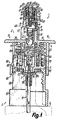
- Fig. 1
- einen erfindungsgemäßen Spender in teilweise geschnittener Ansicht und Ausgangsstellung,
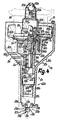
- Fig. 2
- einen weiteren Spender in Ansicht und natürlicher Größe,
- Fig. 3
- einen vergrößerten Ausschnitt der Fig. 2, teilweise im Axialschnitt, und
- Fig. 4
- ein weiterer Spender mit geöffnetem Ventil zu Beginn des Pumphubes und in Überkopflage.
Claims (11)
- Spender für Medien, wie fließfähige Medien, mit einem Grundkörper (4, 4a, 5a), einer Austragbetätigung (8, 8a), einem vom Ausgang (55, 23a) einer Förderkammer (15, 15a) mit Medium zu versorgenden Auslaßkanal (14, 14a), der in einem Medienauslaß (13, 13a) endet, welcher eine Strömungsrichtung (11, 11a) bestimmt, dadurch gekennzeichnet, daß Verschlußmittel, wie ein den Auslaßkanal (14, 14a) in einer Schließstellung an Schließflächen (27, 28; 27a, 28a) schließendendes Ventil (20, 20a) mit einem ersten und zweiten Ventilkörper (25, 26; 25a, 26a), vorgesehen sind, von denen insbesondere der erste Ventilkörper (25, 25a) einschließlich der Schließstellung Ventilstellungen einnimmt und in der Schließstellung zur Ventilöffnung unter einem Mediendruck gegen eine Schließspannung (34, 34a) o. dgl. abhebbar an dem Ventilsitz (28, 28a) des zweiten Ventilkörpers (26, 26a) ansteht, und/oder daß der erste Ventilkörper (25, 25a) zur Ventilöffnung etwa in der Strömungsrichtung (11, 11a) gegenüber dem Ventilsitz (28, 28a), gegebenenfalls seinen äußeren Vorsprung des Spenders (1, 1a) bildend, bewegbar ist.
- Spender nach Anspruch 1, dadurch gekennzeichnet, daß der Auslaßkanal (14, 14a) zur Druckbeaufschlagung mit dem Medium stromaufwärts an den Ausgang (55, 23a) der als Druckkammer ausgebildeten Förderkammer (15, 15a) angeschlossen und der Ausgang mit einem Auslaß-Verschluß (23), wie einem Überdruckventil, verschlossen ist, daß insbesondere Steuermittel (30) zur vorangehenden Öffnung des Auslaß-Verschlusses (23, 23a) und zur nachfolgenden Öffnung des Ventiles (20, 20a) vorgesehen sind, und daß vorzugsweise das Ventil (20, 20a) bei einem niedrigeren Druck als der Auslaß-Verschluß (23, 23a) öffnet.
- Spender nach Anspruch 1 oder 2, dadurchg gekennzeichnet, daß der Ventilsitz (28, 28a) gegenüber dem Grundkörper (4, 4a, 5a) im wesentlichen feststehend angeordnet und der erste Ventilkörper (25, 25a) in Strömungsrichtung (11, 11a) vom Ventilsitz (28, 28a) zum Medienauslaß (13, 13a) hin abhebbar ist, daß insbesondere der erste Ventilkörper (25, 25a) im Ventilsitz (28, 28a) liegt und eine zur Ventilbewegung geneigte Anschlagfläche (27, 27a) für den Ventilsitz (28, 28a) aufweist, und daß vorzugsweise der erste Ventilkörper (25, 25a) einen Ventilkopf (32, 32a) mit einem Ventilschaft (33, 33a) umfaßt, welcher an eine die Schließfläche (27, 27a) aufweisende Stirnseite des Ventilkopfes (32, 32a) entgegen der Strömungsrichtung (11, 11a) anschließt und mit einem Steuerkolben (31, 31a) verbunden ist.
- Spender nach einem der vorhergehenden Ansprüche, dadurch gekennzeichnet, daß der zweite Ventilkörper (26) gesondert vom Grundkörper (4) ausgebildet ist und über diesen vorsteht, daß insbesondere der erste Ventilkörper (25, 25a) den Auslaßkanal (14, 14a) volumenvariabel begrenzt, und daß vorzugsweise der zweite Ventilkörper (26, 26a) ein Gehäuse (40, 40a) bildet, in dem der Steuerkolben (31, 31a) verschiebbar geführt ist.
- Spender nach einem der vorhergehenden Ansprüche, dadurch gekennzeichnet, daß mindestens einer der Ventilkörper (25, 26; 25a, 26a) in einer bis allen Ventilstellungen bis an die frei zugängliche Außenseite des Spenders (1, 1a) reicht, daß insbesondere der erste Ventilkörper (25, 25a) in einer bis allen Ventilstellungen aus dem Medienauslaß (13, 13a) frei zugänglich vorsteht, und daß vorzugsweise der Medienauslaß (13, 13a) durch einen von den Schließflächen (27, 28; 27a, 28a) begrenzten Ringspalt gebildet ist.
- Spender nach einem der vorhergehenden Ansprüche, dadurch gekennzeichnet, daß stromaufwärts des Ventiles (20, 20a) im Auslaßkanal (14, 14a) eine Drossel (21, 22, 23; 21a, 22a, 23a) mit einem engsten Durchlaßquerschnitt für das Medium vorgesehen ist, daß insbesondere der Durchlaßquerschnitt federnd nachgiebig ist, und daß vorzugsweise der Durchlaßquerschnitt der Drossel (21, 22; 21a, 22a) zwischen dem Steuerkolben (31, 31a) und dem Ventil (20, 20a) liegt.
- Spender nach einem der vorhergehenden Ansprüche, dadurch gekennzeichnet, daß der erste Ventilkörper (25, 25a) in einem Auslaßkopf (40, 40a) liegt und gegen Strömungsrichtung (11, 11a) in den Auslaßkopf (40, 40a) eingesetzt ist, daß insbesondere der Grundkörper (4) in der Strömungsrichtung (11) in den hülsenförmigen, vom Auslaßkanal (14) durchsetzten Auslaßkopf (40) hineinragt, und daß vorzugsweise eine Betätigungs-Handhabe (39, 39a) der Austragbetätigung (8, 8a) stromaufwärts vom Medienauslaß (13, 13a) liegt.
- Spender nach einem der vorhergehenden Ansprüche, dadurch gekennzeichnet, daß die Förderkammer (15, 15a) volumenvariabel und von gegeneinander mit der Austragbetätigung (8, 8a) bewegbaren Kammerteilen (64, 71; 62a, 66a) begrenzt ist, von denen ein erster am Grundkörper (4, 4a) angeordnet und ein zweiter einem Tragkörper (5, 5a) zugeordnet ist, daß insbesondere die Kammerteile zwei einander gegenüberliegende und aufeinander zu bewegbare Kammerwandungen, wie einem Pumpkolben (71, 71b) und den Boden eines Pumpzylinders (64, 64b) einer Schubkolbenpumpe (9, 9b), umfassen, und daß vorzugsweise der Pumpzylinder (64) am Grundkörper (4) angeordnet sowie über ein Einlaßventil (70) stromaufwärts an eine ventilfrei an eine Medienzuführung (17) anzuschließende Vorsaugkammer (16) angeschlossen ist.
- Spender nach einem der vorhergehenden Ansprüche, dadurch gekennzeichnet, daß er zur festen Verbindung mit einem die Förderkammer (15, 15b) dosiert mit Medium versorgenden Medienspeicher (6, 6b) ausgebildet ist, daß insbesondere eine Belüftung (18, 18b) mit Entkeimung (80, 80b) für den Medienspeicher (6, 6b) vorgesehen ist, und daß vorzugsweise die Belüftung (18, 18b) stromaufwärts eines Filters (80, 80b) ein mit der Austragbetätigung (8) zu öffnendes Belüftungsventil (24, 24b) und/oder stromabwärts des Filters (80) einen von einem Belüftungskanal (81) durchsetzten Dichtflansch (7) umfaßt, welcher zum Anschluß an eine in den Medienspeicher (6) ragende Steigleitung (17) ausgebildet ist.
- Spender nach einem der vorhergehenden Ansprüche, dadurch gekennzeichnet, daß die Förderkammer (15a) flexibel verformbar und als Speicher- sowie Quetschbehälter (6a) für das Medium ausgebildet ist, daß insbesondere die Förderkammer (15a) an der Außenseite stromabwärts verengt ist, und daß vorzugsweise die Förderkammer (15a) von einer manuell greifbaren Tube begrenzt ist, von der mindestens ein Ende (37a, 7a) den zweiten Ventilkörper (26a) bzw. eine durch Quetschung verschlossene Öffnung zum Einführen der Steuermittel (30a) des ersten Ventilkörpers (25a) und des Mediums bildet.
- Spender nach einem der vorhergehenden Ansprüche, dadurch gekennzeichnet, daß der Medienauslaß (13, 13a) an einen Tropfenformer (50, 50a) zur Sammlung des Mediums in einem außerhalb des Medienauslasses (13, 13a) an dem Tropfenformer (50, 50a) abtropfbar haftenden Medientropfens anschließt, daß insbesondere der Tropfenformer (50, 50a) eine konvex ballige Endfläche (51, 51a) zum Sammeln und Ablösen des Medientropfens aufweist, und daß vorzugsweise die Endfläche (51, 51a) über eine Ringkante (52) an die Schließfläche (27, 27a) des ersten Ventilkörpers (25, 25a) bei geöffnetem Ventil (20, 20a) unmittelbar anschließt.
Applications Claiming Priority (2)
| Application Number | Priority Date | Filing Date | Title |
|---|---|---|---|
| DE19840721A DE19840721A1 (de) | 1998-09-07 | 1998-09-07 | Spender für Medien |
| DE19840721 | 1998-09-07 |
Publications (3)
| Publication Number | Publication Date |
|---|---|
| EP0985454A2 true EP0985454A2 (de) | 2000-03-15 |
| EP0985454A3 EP0985454A3 (de) | 2001-03-07 |
| EP0985454B1 EP0985454B1 (de) | 2006-11-02 |
Family
ID=7880039
Family Applications (1)
| Application Number | Title | Priority Date | Filing Date |
|---|---|---|---|
| EP99117184A Expired - Lifetime EP0985454B1 (de) | 1998-09-07 | 1999-09-01 | Spender für Medien |
Country Status (5)
| Country | Link |
|---|---|
| US (1) | US6250509B1 (de) |
| EP (1) | EP0985454B1 (de) |
| JP (1) | JP4327307B2 (de) |
| AT (1) | ATE344105T1 (de) |
| DE (2) | DE19840721A1 (de) |
Cited By (2)
| Publication number | Priority date | Publication date | Assignee | Title |
|---|---|---|---|---|
| CN107352152A (zh) * | 2016-05-10 | 2017-11-17 | 浙江金马实业有限公司 | 液压泵 |
| US10220988B2 (en) | 2008-03-27 | 2019-03-05 | Nemera La Verpillière | Device for dispensing a liquid in the form of drops |
Families Citing this family (18)
| Publication number | Priority date | Publication date | Assignee | Title |
|---|---|---|---|---|
| DE19933330A1 (de) | 1999-07-16 | 2001-01-18 | Pfeiffer Erich Gmbh & Co Kg | Spender für Medien |
| WO2003026803A1 (de) | 2001-09-21 | 2003-04-03 | Ing. Erich Pfeiffer Gmbh | Dosiervorrichtung mit einer pumpvorrichtung |
| BR0212901B1 (pt) * | 2001-09-21 | 2011-12-13 | dispositivo dosador com um reservatório de meio, bem como dispositivo de bomba para um dispositivo dosador. | |
| FR2830328B1 (fr) * | 2001-09-28 | 2003-12-05 | Socomate Internat | Dispositif et procede d'analyse de la structure d'un materiau |
| DE102005009294A1 (de) * | 2004-07-13 | 2006-02-16 | Ing. Erich Pfeiffer Gmbh | Spender für Medien |
| DE102004044344A1 (de) * | 2004-09-09 | 2006-03-30 | Ing. Erich Pfeiffer Gmbh | Dosiervorrichtung |
| DE102008027599A1 (de) * | 2008-06-10 | 2009-12-31 | Meadwestvaco Calmar Gmbh | Fluidaustragkopf |
| DE102010048085A1 (de) * | 2010-10-04 | 2012-04-05 | Ing. Erich Pfeiffer Gmbh | Austragvorrichtung |
| CN102847627B (zh) * | 2012-10-15 | 2015-04-15 | 深圳市博纳药品包装材料有限公司 | 一种流体制剂分配喷雾泵 |
| ES2734570T3 (es) * | 2013-04-16 | 2019-12-10 | Dance Biopharm Inc | Distribución de líquido |
| AU2014253997B2 (en) * | 2013-04-16 | 2019-01-03 | Aerami Therapeutics, Inc. | Liquid dispensing and methods for dispensing liquids |
| DE102015104646B3 (de) * | 2015-03-26 | 2016-06-30 | Aero Pump Gmbh | Abgabevorrichtung für ein Fluid |
| US9943867B2 (en) * | 2016-05-10 | 2018-04-17 | Zhejiang JM Industry Co., Ltd | Extended emission time liquid sprayer |
| US9981278B2 (en) * | 2016-05-10 | 2018-05-29 | Zhejiang Jm Industry Co., Ltd. | Extended emission time liquid sprayer |
| US10617832B2 (en) * | 2017-11-22 | 2020-04-14 | Southwest Research Institute | High precision, low dose atomizer |
| CN108670809B (zh) * | 2018-08-07 | 2023-11-28 | 朱远湖 | 护理装置手柄、刮痧装置、按摩装置及多功能护理装置 |
| EP3856298B1 (de) * | 2018-09-27 | 2024-02-14 | SHL Medical AG | Verriegelungsmechanismus für einen aerosolspender |
| CN110605288B (zh) * | 2019-10-12 | 2024-07-19 | 广州达意隆包装机械股份有限公司 | 分配器及洗瓶机 |
Family Cites Families (11)
| Publication number | Priority date | Publication date | Assignee | Title |
|---|---|---|---|---|
| US3107035A (en) * | 1960-08-12 | 1963-10-15 | Dougherty Brothers Inc | Squeeze cap for dispensing liquids in drop units |
| US4402432A (en) * | 1980-02-13 | 1983-09-06 | Corsette Douglas Frank | Leak-proof dispensing pump |
| DE3315334A1 (de) * | 1983-04-28 | 1984-10-31 | Pfeiffer Erich Gmbh & Co Kg | Zerstaeuber- oder dosierpumpe |
| DE3503354A1 (de) * | 1985-02-01 | 1986-08-07 | Ing. Erich Pfeiffer GmbH & Co KG, 7760 Radolfzell | Wirkstoff-spender |
| FR2593147B1 (fr) * | 1986-01-17 | 1988-03-18 | Aerosol Inventions Dev | Conditionnement sterile de substances fluides liquides et semi-liquides. |
| US4757922A (en) * | 1986-11-20 | 1988-07-19 | Menda Scientific Products, Inc. | Liquid dispenser |
| US5238153A (en) * | 1991-02-19 | 1993-08-24 | Pilkington Visioncare Inc. | Dispenser for dispersing sterile solutions |
| DE4210225A1 (de) * | 1992-03-28 | 1993-09-30 | Katz Otto | Spender für Flüssigkeiten und Pasten |
| US5687878A (en) * | 1994-04-15 | 1997-11-18 | Owens-Brockway Plastic Products Inc. | Flexible tube with pump dispenser and method of making |
| DE19610457A1 (de) * | 1996-03-16 | 1997-09-18 | Pfeiffer Erich Gmbh & Co Kg | Austragvorrichtung für Medien |
| DE19627228A1 (de) * | 1996-07-05 | 1998-01-08 | Pfeiffer Erich Gmbh & Co Kg | Austragvorrichtung für Medien |
-
1998
- 1998-09-07 DE DE19840721A patent/DE19840721A1/de not_active Withdrawn
-
1999
- 1999-09-01 AT AT99117184T patent/ATE344105T1/de not_active IP Right Cessation
- 1999-09-01 DE DE59913956T patent/DE59913956D1/de not_active Expired - Lifetime
- 1999-09-01 EP EP99117184A patent/EP0985454B1/de not_active Expired - Lifetime
- 1999-09-02 US US09/388,517 patent/US6250509B1/en not_active Expired - Fee Related
- 1999-09-03 JP JP25046699A patent/JP4327307B2/ja not_active Expired - Fee Related
Cited By (6)
| Publication number | Priority date | Publication date | Assignee | Title |
|---|---|---|---|---|
| US10220988B2 (en) | 2008-03-27 | 2019-03-05 | Nemera La Verpillière | Device for dispensing a liquid in the form of drops |
| US10640268B2 (en) | 2008-03-27 | 2020-05-05 | Nemera La Verpillière | Device for dispensing a liquid in the form of drops |
| EP2257476B2 (de) † | 2008-03-27 | 2021-02-24 | Nemera La Verpilliere | Vorrichtung zur ausgabe einer flüssigkeit in tropfenform |
| US11155391B2 (en) | 2008-03-27 | 2021-10-26 | Nemera La Verpillière | Device for dispensing a liquid in the form of drops |
| US11524822B2 (en) | 2008-03-27 | 2022-12-13 | Nemera La Verpillière | Device for dispensing a liquid in the form of drops |
| CN107352152A (zh) * | 2016-05-10 | 2017-11-17 | 浙江金马实业有限公司 | 液压泵 |
Also Published As
| Publication number | Publication date |
|---|---|
| ATE344105T1 (de) | 2006-11-15 |
| DE59913956D1 (de) | 2006-12-14 |
| JP4327307B2 (ja) | 2009-09-09 |
| EP0985454A3 (de) | 2001-03-07 |
| DE19840721A1 (de) | 2000-03-09 |
| US6250509B1 (en) | 2001-06-26 |
| EP0985454B1 (de) | 2006-11-02 |
| JP2000116782A (ja) | 2000-04-25 |
Similar Documents
| Publication | Publication Date | Title |
|---|---|---|
| EP0985454B1 (de) | Spender für Medien | |
| EP0985606A2 (de) | Spender für Medien | |
| DE69820189T2 (de) | System und Verfahren für Sprüh- oder Aerosolspitze mit Einweg-Strömung | |
| EP0312722B1 (de) | Dosier- und Spraypumpe für flüssige oder viskose Stoffe | |
| EP0923993B1 (de) | Spender für fliessfähige Medien | |
| DE69503369T2 (de) | Pumpe mit vordruckaufbau | |
| EP0815946B1 (de) | Spender für Medien | |
| EP0775530B1 (de) | Spender mit zwei Fördereinheiten | |
| DE69507979T2 (de) | Abgabepumpe | |
| DE69919321T2 (de) | Zerstäubungskopf für einen spender für medien | |
| EP0882516B1 (de) | Spender für Medien | |
| DE3315334A1 (de) | Zerstaeuber- oder dosierpumpe | |
| WO2003026803A1 (de) | Dosiervorrichtung mit einer pumpvorrichtung | |
| EP0901836B1 (de) | Spender für Medien | |
| EP1068906B1 (de) | Spender für Medien | |
| EP3552644A1 (de) | Austragkopf für die nasale applikation von flüssigkeit aus einem druckspeicher | |
| EP0692313B1 (de) | Austragvorrichtung für Medien | |
| DE69714025T2 (de) | Verteilungseinrichtung einer einmaligen dosis eines flüssigen produktes | |
| EP0901835B1 (de) | Spender für Medien | |
| DE3828811A1 (de) | Dosier- und spraypumpe fuer fluessige und niederviskose stoffe | |
| DE3834091C2 (de) | ||
| EP3736049A1 (de) | Austragkopf und flüssigkeitsspender mit einem austragkopf | |
| DE3525449C2 (de) | Ausgabe-Einrichtung für fließfähige Medien | |
| DE60316527T2 (de) | Behälter mit einer Pumpe | |
| EP0882515A2 (de) | Spender für Medien |
Legal Events
| Date | Code | Title | Description |
|---|---|---|---|
| PUAI | Public reference made under article 153(3) epc to a published international application that has entered the european phase |
Free format text: ORIGINAL CODE: 0009012 |
|
| AK | Designated contracting states |
Kind code of ref document: A2 Designated state(s): AT BE CH CY DE DK ES FI FR GB GR IE IT LI LU MC NL PT SE |
|
| AX | Request for extension of the european patent |
Free format text: AL;LT;LV;MK;RO;SI |
|
| PUAL | Search report despatched |
Free format text: ORIGINAL CODE: 0009013 |
|
| AK | Designated contracting states |
Kind code of ref document: A3 Designated state(s): AT BE CH CY DE DK ES FI FR GB GR IE IT LI LU MC NL PT SE |
|
| AX | Request for extension of the european patent |
Free format text: AL;LT;LV;MK;RO;SI |
|
| 17P | Request for examination filed |
Effective date: 20010830 |
|
| AKX | Designation fees paid |
Free format text: AT BE CH CY DE DK ES FI FR GB GR IE IT LI LU MC NL PT SE |
|
| 17Q | First examination report despatched |
Effective date: 20040719 |
|
| GRAP | Despatch of communication of intention to grant a patent |
Free format text: ORIGINAL CODE: EPIDOSNIGR1 |
|
| GRAS | Grant fee paid |
Free format text: ORIGINAL CODE: EPIDOSNIGR3 |
|
| GRAA | (expected) grant |
Free format text: ORIGINAL CODE: 0009210 |
|
| AK | Designated contracting states |
Kind code of ref document: B1 Designated state(s): AT BE CH CY DE DK ES FI FR GB GR IE IT LI LU MC NL PT SE |
|
| PG25 | Lapsed in a contracting state [announced via postgrant information from national office to epo] |
Ref country code: NL Free format text: LAPSE BECAUSE OF FAILURE TO SUBMIT A TRANSLATION OF THE DESCRIPTION OR TO PAY THE FEE WITHIN THE PRESCRIBED TIME-LIMIT Effective date: 20061102 Ref country code: IE Free format text: LAPSE BECAUSE OF FAILURE TO SUBMIT A TRANSLATION OF THE DESCRIPTION OR TO PAY THE FEE WITHIN THE PRESCRIBED TIME-LIMIT Effective date: 20061102 Ref country code: FI Free format text: LAPSE BECAUSE OF FAILURE TO SUBMIT A TRANSLATION OF THE DESCRIPTION OR TO PAY THE FEE WITHIN THE PRESCRIBED TIME-LIMIT Effective date: 20061102 |
|
| REG | Reference to a national code |
Ref country code: GB Ref legal event code: FG4D Free format text: NOT ENGLISH |
|
| GBT | Gb: translation of ep patent filed (gb section 77(6)(a)/1977) |
Effective date: 20061102 |
|
| REG | Reference to a national code |
Ref country code: IE Ref legal event code: FG4D Free format text: LANGUAGE OF EP DOCUMENT: GERMAN |
|
| REG | Reference to a national code |
Ref country code: CH Ref legal event code: EP |
|
| REF | Corresponds to: |
Ref document number: 59913956 Country of ref document: DE Date of ref document: 20061214 Kind code of ref document: P |
|
| REG | Reference to a national code |
Ref country code: CH Ref legal event code: NV Representative=s name: ZIMMERLI, WAGNER & PARTNER AG |
|
| REG | Reference to a national code |
Ref country code: SE Ref legal event code: TRGR |
|
| PG25 | Lapsed in a contracting state [announced via postgrant information from national office to epo] |
Ref country code: DK Free format text: LAPSE BECAUSE OF FAILURE TO SUBMIT A TRANSLATION OF THE DESCRIPTION OR TO PAY THE FEE WITHIN THE PRESCRIBED TIME-LIMIT Effective date: 20070202 |
|
| PG25 | Lapsed in a contracting state [announced via postgrant information from national office to epo] |
Ref country code: ES Free format text: LAPSE BECAUSE OF FAILURE TO SUBMIT A TRANSLATION OF THE DESCRIPTION OR TO PAY THE FEE WITHIN THE PRESCRIBED TIME-LIMIT Effective date: 20070213 |
|
| PG25 | Lapsed in a contracting state [announced via postgrant information from national office to epo] |
Ref country code: PT Free format text: LAPSE BECAUSE OF FAILURE TO SUBMIT A TRANSLATION OF THE DESCRIPTION OR TO PAY THE FEE WITHIN THE PRESCRIBED TIME-LIMIT Effective date: 20070402 |
|
| NLV1 | Nl: lapsed or annulled due to failure to fulfill the requirements of art. 29p and 29m of the patents act | ||
| ET | Fr: translation filed | ||
| REG | Reference to a national code |
Ref country code: IE Ref legal event code: FD4D |
|
| PLBE | No opposition filed within time limit |
Free format text: ORIGINAL CODE: 0009261 |
|
| STAA | Information on the status of an ep patent application or granted ep patent |
Free format text: STATUS: NO OPPOSITION FILED WITHIN TIME LIMIT |
|
| 26N | No opposition filed |
Effective date: 20070803 |
|
| PG25 | Lapsed in a contracting state [announced via postgrant information from national office to epo] |
Ref country code: MC Free format text: LAPSE BECAUSE OF NON-PAYMENT OF DUE FEES Effective date: 20070930 Ref country code: GR Free format text: LAPSE BECAUSE OF FAILURE TO SUBMIT A TRANSLATION OF THE DESCRIPTION OR TO PAY THE FEE WITHIN THE PRESCRIBED TIME-LIMIT Effective date: 20070203 |
|
| PG25 | Lapsed in a contracting state [announced via postgrant information from national office to epo] |
Ref country code: AT Free format text: LAPSE BECAUSE OF NON-PAYMENT OF DUE FEES Effective date: 20070901 |
|
| PG25 | Lapsed in a contracting state [announced via postgrant information from national office to epo] |
Ref country code: LU Free format text: LAPSE BECAUSE OF NON-PAYMENT OF DUE FEES Effective date: 20070901 Ref country code: CY Free format text: LAPSE BECAUSE OF FAILURE TO SUBMIT A TRANSLATION OF THE DESCRIPTION OR TO PAY THE FEE WITHIN THE PRESCRIBED TIME-LIMIT Effective date: 20061102 |
|
| REG | Reference to a national code |
Ref country code: CH Ref legal event code: PFA Owner name: ING. ERICH PFEIFFER GMBH Free format text: ING. ERICH PFEIFFER GMBH#OESCHLESTRASSE 124-126#78315 RADOLFZELL (DE) -TRANSFER TO- ING. ERICH PFEIFFER GMBH#OESCHLESTRASSE 124-126#78315 RADOLFZELL (DE) |
|
| PGFP | Annual fee paid to national office [announced via postgrant information from national office to epo] |
Ref country code: SE Payment date: 20100921 Year of fee payment: 12 |
|
| PGFP | Annual fee paid to national office [announced via postgrant information from national office to epo] |
Ref country code: BE Payment date: 20110926 Year of fee payment: 13 |
|
| REG | Reference to a national code |
Ref country code: SE Ref legal event code: EUG |
|
| REG | Reference to a national code |
Ref country code: DE Ref legal event code: R082 Ref document number: 59913956 Country of ref document: DE Representative=s name: PATENTANWALTSKANZLEI CARTAGENA PARTNERSCHAFTSG, DE Effective date: 20121025 Ref country code: DE Ref legal event code: R082 Ref document number: 59913956 Country of ref document: DE Representative=s name: PATENTANWAELTE RUFF, WILHELM, BEIER, DAUSTER &, DE Effective date: 20121025 Ref country code: DE Ref legal event code: R081 Ref document number: 59913956 Country of ref document: DE Owner name: APTAR RADOLFZELL GMBH, DE Free format text: FORMER OWNER: ING. ERICH PFEIFFER GMBH, 78315 RADOLFZELL, DE Effective date: 20121025 |
|
| BERE | Be: lapsed |
Owner name: ING. ERICH PFEIFFER G.M.B.H. Effective date: 20120930 |
|
| PG25 | Lapsed in a contracting state [announced via postgrant information from national office to epo] |
Ref country code: SE Free format text: LAPSE BECAUSE OF NON-PAYMENT OF DUE FEES Effective date: 20110902 |
|
| PG25 | Lapsed in a contracting state [announced via postgrant information from national office to epo] |
Ref country code: BE Free format text: LAPSE BECAUSE OF NON-PAYMENT OF DUE FEES Effective date: 20120930 |
|
| PGFP | Annual fee paid to national office [announced via postgrant information from national office to epo] |
Ref country code: CH Payment date: 20130923 Year of fee payment: 15 |
|
| PGFP | Annual fee paid to national office [announced via postgrant information from national office to epo] |
Ref country code: IT Payment date: 20130926 Year of fee payment: 15 |
|
| REG | Reference to a national code |
Ref country code: CH Ref legal event code: NV Representative=s name: WAGNER PATENT AG, CH |
|
| PGFP | Annual fee paid to national office [announced via postgrant information from national office to epo] |
Ref country code: GB Payment date: 20140923 Year of fee payment: 16 |
|
| PGFP | Annual fee paid to national office [announced via postgrant information from national office to epo] |
Ref country code: FR Payment date: 20140917 Year of fee payment: 16 |
|
| REG | Reference to a national code |
Ref country code: CH Ref legal event code: PL |
|
| PG25 | Lapsed in a contracting state [announced via postgrant information from national office to epo] |
Ref country code: CH Free format text: LAPSE BECAUSE OF NON-PAYMENT OF DUE FEES Effective date: 20140930 Ref country code: LI Free format text: LAPSE BECAUSE OF NON-PAYMENT OF DUE FEES Effective date: 20140930 |
|
| PG25 | Lapsed in a contracting state [announced via postgrant information from national office to epo] |
Ref country code: IT Free format text: LAPSE BECAUSE OF NON-PAYMENT OF DUE FEES Effective date: 20140901 |
|
| REG | Reference to a national code |
Ref country code: DE Ref legal event code: R082 Ref document number: 59913956 Country of ref document: DE Representative=s name: PATENTANWALTSKANZLEI CARTAGENA PARTNERSCHAFTSG, DE |
|
| GBPC | Gb: european patent ceased through non-payment of renewal fee |
Effective date: 20150901 |
|
| REG | Reference to a national code |
Ref country code: FR Ref legal event code: ST Effective date: 20160531 |
|
| PG25 | Lapsed in a contracting state [announced via postgrant information from national office to epo] |
Ref country code: GB Free format text: LAPSE BECAUSE OF NON-PAYMENT OF DUE FEES Effective date: 20150901 |
|
| PG25 | Lapsed in a contracting state [announced via postgrant information from national office to epo] |
Ref country code: FR Free format text: LAPSE BECAUSE OF NON-PAYMENT OF DUE FEES Effective date: 20150930 |
|
| PGFP | Annual fee paid to national office [announced via postgrant information from national office to epo] |
Ref country code: DE Payment date: 20170920 Year of fee payment: 19 |
|
| REG | Reference to a national code |
Ref country code: DE Ref legal event code: R119 Ref document number: 59913956 Country of ref document: DE |
|
| PG25 | Lapsed in a contracting state [announced via postgrant information from national office to epo] |
Ref country code: DE Free format text: LAPSE BECAUSE OF NON-PAYMENT OF DUE FEES Effective date: 20190402 |