EP0985465B1 - Vorrichtung und Verformungsverfahren - Google Patents
Vorrichtung und Verformungsverfahren Download PDFInfo
- Publication number
- EP0985465B1 EP0985465B1 EP99117554A EP99117554A EP0985465B1 EP 0985465 B1 EP0985465 B1 EP 0985465B1 EP 99117554 A EP99117554 A EP 99117554A EP 99117554 A EP99117554 A EP 99117554A EP 0985465 B1 EP0985465 B1 EP 0985465B1
- Authority
- EP
- European Patent Office
- Prior art keywords
- workpiece
- bulging
- pressure
- dies
- pressure liquid
- Prior art date
- Legal status (The legal status is an assumption and is not a legal conclusion. Google has not performed a legal analysis and makes no representation as to the accuracy of the status listed.)
- Expired - Lifetime
Links
- 238000000034 method Methods 0.000 title description 10
- 239000007788 liquid Substances 0.000 claims description 41
- 238000006073 displacement reaction Methods 0.000 claims description 14
- 230000015572 biosynthetic process Effects 0.000 claims description 7
- 238000004519 manufacturing process Methods 0.000 claims 4
- 230000013011 mating Effects 0.000 claims 4
- 239000012530 fluid Substances 0.000 description 11
- 239000000463 material Substances 0.000 description 11
- 238000001514 detection method Methods 0.000 description 10
- 230000008961 swelling Effects 0.000 description 6
- 238000007789 sealing Methods 0.000 description 3
- 230000005540 biological transmission Effects 0.000 description 1
- 230000001419 dependent effect Effects 0.000 description 1
- 238000010586 diagram Methods 0.000 description 1
- 230000001976 improved effect Effects 0.000 description 1
- 230000002265 prevention Effects 0.000 description 1
Images




Classifications
-
- B—PERFORMING OPERATIONS; TRANSPORTING
- B21—MECHANICAL METAL-WORKING WITHOUT ESSENTIALLY REMOVING MATERIAL; PUNCHING METAL
- B21D—WORKING OR PROCESSING OF SHEET METAL OR METAL TUBES, RODS OR PROFILES WITHOUT ESSENTIALLY REMOVING MATERIAL; PUNCHING METAL
- B21D24/00—Special deep-drawing arrangements in, or in connection with, presses
-
- B—PERFORMING OPERATIONS; TRANSPORTING
- B21—MECHANICAL METAL-WORKING WITHOUT ESSENTIALLY REMOVING MATERIAL; PUNCHING METAL
- B21D—WORKING OR PROCESSING OF SHEET METAL OR METAL TUBES, RODS OR PROFILES WITHOUT ESSENTIALLY REMOVING MATERIAL; PUNCHING METAL
- B21D26/00—Shaping without cutting otherwise than using rigid devices or tools or yieldable or resilient pads, i.e. applying fluid pressure or magnetic forces
- B21D26/02—Shaping without cutting otherwise than using rigid devices or tools or yieldable or resilient pads, i.e. applying fluid pressure or magnetic forces by applying fluid pressure
- B21D26/033—Deforming tubular bodies
- B21D26/041—Means for controlling fluid parameters, e.g. pressure or temperature
-
- Y—GENERAL TAGGING OF NEW TECHNOLOGICAL DEVELOPMENTS; GENERAL TAGGING OF CROSS-SECTIONAL TECHNOLOGIES SPANNING OVER SEVERAL SECTIONS OF THE IPC; TECHNICAL SUBJECTS COVERED BY FORMER USPC CROSS-REFERENCE ART COLLECTIONS [XRACs] AND DIGESTS
- Y10—TECHNICAL SUBJECTS COVERED BY FORMER USPC
- Y10T—TECHNICAL SUBJECTS COVERED BY FORMER US CLASSIFICATION
- Y10T29/00—Metal working
- Y10T29/49—Method of mechanical manufacture
- Y10T29/49805—Shaping by direct application of fluent pressure
Definitions
- the present invention relates to a bulging method and device according to the preamble of claim 1 or 5.
- a bulging device for bulging a workpiece such as a tube which is inserted into a cavity formed between an upper and lower die, into, for example, a T shape by supplying high pressure liquid to the interior space of the workpiece has been used.
- a bulging device is disclosed in JP-A-7-155857.
- the bulging device comprises a regulation stopper which is slidable in a swelling formation hole of a die and a control device for controlling movement of the regulation stopper.
- a regulation stopper which is slidable in a swelling formation hole of a die and a control device for controlling movement of the regulation stopper.
- the cylindrical shape of which the sectional form is constant in the longitudinal direction can be applied to the shape of the swelling formation hole, while the shape of which the sectional form is variable in the longitudinal direction, such as a bowl shape, can not be applied thereto.
- the shape of dies applicable to the aforementioned device is thus limited, which has been a continuing problem.
- WO 00/12240 discloses a generic bulging method and device in which the workpiece is inserted into a cavity formed by an upper and lower die, and in which high pressure liquid is supplied to the interior space of the workpiece, an axial compressive force being applied to the workpiece, thereby bulging the workpiece along the shape of the inwardly facing surfaces of the dies. Either the dies or the workpiece are subjected to an oscillator so as to reduce the friction between the workpiece and the dies during the bulging process.
- JP-A-61189835, EP-A-0 740 969 and EP-A-0 036 365 each suggest a constant application of the high pressure liquid supplied to the interior space of the workpiece during bulging.
- EP-A-0 633 075 suggests a fine control of the high pressure liquid supplied to the interior space of the workpiece during bulging where any fluctuation of the pressure is suppressed.
- the object is solved by the bulging method having the features of the new claim 1 and a bulging device having the features of the new claim 5.
- the fluctuation of pressure may be a periodical fluctuation.
- the pressure in the contact area of the outer surface of the workpiece with the inwardly facing surface of the dies can thus be fluctuated by fluctuating the pressure of the pressure liquid supplied to the interior space of the workpiece and/or the pressure of the pressure liquid supplied to the outer space when the workpiece is bulged and deformed, which also results in the fluctuation of frictional resistance between the workpiece and the dies in the aforementioned contact area.
- the flow resistance which is caused by frictional forces, of the material of the workpiece, can be reduced at the predetermined time intervals, thereby allowing the material to flow smoothly along the shape or contour of the inwardly facing surface of the dies.
- the workpiece can be effectively prevented from becoming locally thin and thus from being cracked, and a precise bulging along the shape or contour of the inwardly facing surface of the dies can be achieved, which are the results of the present invention.
- the dies 1 are composed of a first upper die 2 and a second lower die 4, and the upper die 2 and the lower die 4 are mounted on a press machine for bulging (not shown).
- a cavity 6 is formed within the pair of dies 1 when the upper die 2 and the lower die 4 are mated with one another.
- a workpiece 8, for which a tube is employed in this embodiment, is inserted into the cavity 6.
- the inwardly facing surface of the dies 1, defining the cavity 6, is formed of such a shape as to allow the middle section of the workpiece 8 to expand by bulging.
- a pair of first and second pushing dies 10 and 12 are slidably disposed at both opposed ends of the workpiece 8 which is inserted into the cavity 6 of the dies 1.
- the outer shape or contour of the pushing dies 10 and 12 substantially coincides with or follows the inner shape or contour of the dies 1, and further, a known sealing structure is provided between the pushing die 10 and the dies 1 as well as between the pushing die 12 and the dies 1, thereby providing an airtight sealing arrangement therebetween.
- O rings may be disposed between the pushing die 10 and the dies 1 as well as between the pushing die 12 and the dies 1.
- the pushing dies 10 and 12 are actuated by hydraulic cylinders 14 and 16, respectively, to apply an axial compressive force to the workpiece 8.
- the hydraulic cylinders 14 and 16 are connected to hydraulic sources 18 and 19, respectively.
- the hydraulic sources 18 and 19 are provided for supplying high pressure liquid to the hydraulic cylinders 14 and 16, respectively, and for adjusting the pressure of the pressure liquid according to external signals.
- a pushing mechanism 20 is composed of the hydraulic cylinder 14 and the hydraulic source 18, and a pushing mechanism 21 is composed of the hydraulic cylinder 16 and the hydraulic source 19.
- An interior space of the workpiece 8 is connected with a first booster 22 via a communicating passage or hole 24 formed in the pushing die 10.
- the outer space of the workpiece 8 when located within the cavity 6 (hereinafter referred to as the "outer space") is connected with a second booster 26 via a communicating passage or hole 25.
- the first and second boosters 22 and 26 are connected to hydraulic sources 28 and 29, respectively, such as hydraulic pumps.
- the hydraulic sources 28 and 29 are provided for supplying a high pressure liquid to the first and second boosters 22 and 26, respectively, and for adjusting the pressure of the pressure liquid according to external signals.
- the first and second boosters 22 and 26 intensify the pressure of the pressure liquid supplied from the hydraulic sources 28 and 29, respectively, and then, supply the intensified pressure liquid to the interior space of the workpiece 8 and the outer space, respectively.
- an internal pressure supply mechanism 30 is composed of the first booster 22 and the hydraulic source 28
- an external pressure supply mechanism 31 is composed of the second booster 26 and the hydraulic source 29.
- position sensors 32 and 34 for detecting displacement of the pushing dies 10 and 12, respectively. Also provided are an internal pressure detection sensor 36, for detecting the pressure of the pressure liquid supplied from the first booster 22 to the interior space of the workpiece 8, and an external pressure detection sensor 38, for detecting the pressure of the pressure liquid from the second booster 26 to the outer space.
- the position sensors 32 and 34, the internal pressure detection sensor 36 and the external pressure detection sensor 38 are all connected to a control circuit 40.
- the control circuit 40 outputs signals, such as a drive signal for driving a hydraulic pump and a pressure setting signal for setting the pressure of the pressure liquid, according to the signals received form each of the sensors 32, 34, 36 and 38, and also transmits output signals to each of the hydraulic sources 18, 19, 28 and 29.
- control circuit 40 comprises an I/O interface for transmission and reception of signals between each sensor 32, 34, 36, 38 and each hydraulic source 18, 19, 28, 29, a CPU for providing various kinds of control commands, a ROM for storing control programs, and a RAM for temporarily retaining various data.
- the workpiece 8 is inserted into the cavity 6, and the hydraulic cylinders 14 and 16 are then actuated by being supplied with hydraulic fluid from the hydraulic sources 18 and 19, respectively, such that the front face of each of the pushing dies 10 and 12 contacts an end face of the workpiece 8.
- the interior space of the workpiece 8 and the outer space are then filled with low pressure liquid via the communicating holes 24 and 25, respectively, while the first and second boosters 22 and 26 are supplied with high pressure liquid from the hydraulic sources 28 and 29, respectively.
- An intensified high pressure liquid is supplied, from the first booster 22 via the communicating hole 24, to the interior space of the workpiece 8, while an intensified high pressure liquid is supplied, from the second booster 26 via the communicating hole 25, to the outer space.
- hydraulic fluid is supplied from the hydraulic sources 18 and 19 to the hydraulic cylinders 14 and 16 to apply an axial compressive force to the workpiece 8 via the pushing dies 10 and 12.
- the workpiece 8 expands, due to the pressure thereof, to follow or conform to the shape of the inwardly facing surface of the dies 1. Since the axial compressive force is being applied to the workpiece 8 via the pushing dies 10 and 12, the pushing dies 10 and 12 are displaced in the axial direction with the expansion of the workpiece 8. At the same time, the intensified high pressure liquid is supplied, via the second booster 26, to the outer space.
- the workpiece 8 is expanded to conform to the shape of the inwardly facing surface of the dies 1 due to the pressure differentials therebetween.
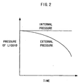
- the pressure of the interior space of the workpiece 8 and the pressure of the outer space may both be increased as time passes.
- the degree of increase in the pressure of the interior space of the workpiece 8 should be larger than that of the pressure of the outer space.
- the degree of increase in pressure differentials may be determined according to the material composition and thickness of the workpiece 8.
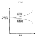
- the pressure of the interior space of the workpiece 8 is increased while the pressure of the outer space is reduced with the passage of time.
- the degree of increase or reduction in the pressure may be determined according to the material composition and thickness of the workpiece 8.
- the progress of bulging of the workpiece 8 can be seen from the displacement of the pushing dies 10 and 12, which is detected by the position sensors 32 and 34, respectively. More specifically, as the bulging of the workpiece 8 progresses, the displacement of the pushing dies 10 and 12 becomes larger. Then, it is proposed to monitor displacement of the pushing dies 10 and 12, and to control the hydraulic source 28, thereby adjusting the pressure of the interior space of the workpiece 8.
- the pressure of the interior space of the workpiece 8 and the pressure of the outer space may be controlled in the same manner as shown in Figs. 2, 3 and 4.
- the abscissa of each graph shows displacement, not time.
- the material flow of the workplace 8 can be precisely controlled at the time the workpiece 8 is bulged and deformed and, therefore, it can be accurately bulged along the shape of or to conform to the inwardly facing surface of the dies 1.
- this mode can be applied to the aforementioned control mode based on time.
- the present invention also proposes to fluctuate the pressure liquid supplied to the interior space of the workpiece 8 and/or the pressure of the pressure liquid supplied to the outer space during bulging.
- the hydraulic source 28 may be controlled by the control circuit 40, thereby fluctuating the pressure of the hydraulic fluid supplied from the hydraulic source 28 to the booster 22. Consequently, the pressure of the high pressure liquid supplied from the booster 22 to the interior space of the workpiece 8 is fluctuated as well.
- the pressure of the hydraulic fluid from the hydraulic source 28, as shown in Fig. 6A is fluctuated as a periodical rectangular wave.
- the pressure of the hydraulic fluid may be fluctuated as a periodical sine wave, as shown in Fig. 6B.
- the pressure of the high pressure liquid supplied from the booster 22 to the interior space of the workpiece 8 is fluctuated in a rectangular wave and, consequently, the pressure of the contact area of the outer surface of the workpiece 8 with the inwardly facing surface of the dies 1 is fluctuated as well, which also results in the fluctuation of the frictional resistance between the workpiece 8 and the dies 1 in the contact area. That is, the flow resistance of the material of the workpiece 8 caused by the aforementioned frictional force can be reduced at the predetermined time intervals. The material easily flows when the flow resistance is small. Therefore, the material can smoothly flow along the shape or contour of the inwardly facing surface of the dies 1.
- the workpiece 8 can be effectively prevented from becoming locally thin and thus from being cracked during bulging, and a precise bulging along the shape or contour of the inwardly facing surface of the dies 1 can be achieved.
- the proper values of the aforementioned fluctuation period and fluctuation amplitude of pressure may be determined, in advance, according to the type of workpiece 8 through tests.
- the hydraulic source 29 may be controlled by the control circuit 40 to fluctuate the pressure of the hydraulic fluid supplied from the hydraulic source 29 to the booster 26, thereby bulging the workpiece 8 in the same manner as aforementioned. Furthermore, it is also possible that the pressure of the hydraulic fluid from the hydraulic source 28 and the pressure of the hydraulic fluid from the hydraulic source 29 are both fluctuated during bulging.
- the pressure of the interior space of the workpiece 8 is fluctuated by controlling the hydraulic source 28 according to the displacement of the pushing dies 10 and 12.
- the pressure of the outer space may be fluctuated by controlling the hydraulic source 29 according to the displacement of the pushing dies 10 and 12.
- the pressure of the hydraulic fluid from the hydraulic source 28 and the pressure of the hydraulic fluid from the hydraulic source 29 may both be fluctuated according to the displacement of the pushing dies 10 and 12.
- the pressure of the interior space of the workpiece 8 is fluctuated when the displacement of the pushing dies 10 and 12 exceeds a predetermined threshold, thereby making it possible to precisely bulge the workpiece 8, especially at the last stage of the bulging process, along the shape or contour of the inwardly facing surface of the dies 1.
- a periodical rectangular wave and a periodical sine wave are indicated as a fluctuation manner of the pressure of hydraulic fluid; however, needless to say, it may be a triangular wave, a trapezoidal wave, and other various waves.
- bulging can be performed under atmospheric pressure, but it is of course possible to perform the bulging in a special external environment, that is under a high pressure or the like.
Landscapes
- Engineering & Computer Science (AREA)
- Mechanical Engineering (AREA)
- Physics & Mathematics (AREA)
- Fluid Mechanics (AREA)
- Shaping Metal By Deep-Drawing, Or The Like (AREA)
Claims (8)
- Ausbauchungsverfahren zum Erzeugen von Ausbauchungen in einem Werkstück (8), während eine Rissbildung und ein Ausdünnen des Werkstückes während des Ausbauchens minimiert wird, bei dem das Werkstück (8) in einen Hohlraum (6) eingefügt wird, der durch ein Paar bestehend aus einem ersten und einem zweiten zusammenpassenden Werkzeug (2, 4) ausgebildet ist, und bei dem eine Hochdruckflüssigkeit dem Innenraum des Werkstückes (8) zugeführt wird, wobei eine axiale Kompressionskraft auf das Werkstück (8) aufgebracht wird, um dadurch das Werkstück entlang der Form der nach innen gerichteten Flächen des Werkzeugpaares bestehend aus dem ersten und dem zweiten zusammenpasssenden Werkzeug (2, 4) auszubauchen,
gekennzeichnet durch einen Schritt zum
Schwanken des Druckes der dem Innenraum des Werkstückes (8) zugeführten Hochdruckflüssigkeit während des Ausbauchens. - Ausbauchungsverfahren zum Erzeugen von Ausbauchungen in einem Werkstück (8) gemäß Anspruch 1,
wobei die axiale Kompressionskraft mittels eines Druckmechanismus (20) mit einem Paar bestehend aus einem ersten und einem zweiten Druckwerkzeug (10, 12) aufgebracht wird, und
wobei der Druck darin geschwankt wird, wenn eine Versetzung der Druckwerkzeuge (10, 12) einen vorbestimmten Schwellwert überschreitet. - Ausbauchungsverfahren zum Erzeugen von Ausbauchungen in einem Werkstück (8) gemäß Anspruch 1 oder 2,
mit einem Schritt zum Steuern einer Hydraulikquelle (28) zum Zuführen des Druckes der Hochdruckflüssigkeit zu dem Innenraum des Werkstückes (8), um den Druck zu schwanken. - Ausbauchungsverfahren zum Erzeugen von Ausbauchungen in einem Werkstück (8) gemäß einem der vorherigen Ansprüche,
mit Schritten
zum Zuführen einer Hochdruckflüssigkeit zu einem Außenraum, der zwischen einer nach innen gerichteten Kontur des Hohlraumes (6) und einer Außenfläche des Werkstückes (8) definiert ist; und
Schwanken des Druckes der dem Außenraum zugeführten Hochdruckflüssigkeit während des Ausbauchens. - Ausbauchungsvorrichtung zum Erzeugen von Ausbauchungen in einem Werkstück (8), während eine Rissbildung und ein Ausdünnen des Werkstückes während des Ausbauchens minimiert ist, mit:wobei eine axiale Kompressionskraft auf das Werkstück (8) aufgebracht wird;einem Paar bestehend aus einem ersten und einem zweiten zusammenpassenden Werkzeug (2, 4), die einen Hohlraum (6) bilden, in den das Werkstück einzufügen ist;einer Hydraulikquelle (28) zum Zuführen einer Hochdruckflüssigkeit zu einem Innenraum des Werkstückes (8),
um dadurch das Werkstück entlang der Form der nach innen gerichteten Flächen des Paares bestehend aus dem ersten und dem zweiten zusammenpassenden Werkzeug (2, 4) auszubauchen,
gekennzeichnet durch
eine Steuerschaltung (40), die die Hydraulikquelle (28) während des Ausbauchens so steuert, dass der Druck schwankt. - Ausbauchungsvorrichtung zum Erzeugen von Ausbauchungen in einem Werkstück (8) gemäß Anspruch 5,
mit einem Druckmechanismus (20) mit Druckwerkzeugen (10, 12) zum Aufbringen der axialen Kompressionskraft auf das Werkstück (8). - Ausbauchungsverfahren zum Erzeugen von Ausbauchungen in einem Werkstück (8) gemäß Anspruch 6,
wobei die Steuerschaltung (40) die Hydraulikquelle (28) während des Ausbauchens so steuert, dass der Druck schwankt, wenn eine Versetzung der Druckwerkzeuge (10, 12) einen vorbestimmten Schwellwert überschreitet. - Ausbauchungsvorrichtung zum Erzeugen von Ausbauchungen in einem Werkstück (8) gemäß Anspruch 6 oder 7, mit:einer Hydraulikquelle (29) zum Zuführen einer Hochdruckflüssigkeit zu einem Außenraum des Werkstückes (8) zwischen einer nach innen gerichteten Kontur des Hohlraumes (6) und einer Außenfläche des Werkstückes (8), wobei die Steuerschaltung (40) die Hydraulikquelle (29) steuert, um den Druck der dem Außenraum zugeführtew Hochdruckflüssigkeit während des Ausbauchens zu schwanken.
Applications Claiming Priority (4)
| Application Number | Priority Date | Filing Date | Title |
|---|---|---|---|
| JP25511998 | 1998-09-09 | ||
| JP10255118A JP3022506B1 (ja) | 1998-09-09 | 1998-09-09 | バルジ加工装置 |
| JP10255119A JP2999757B1 (ja) | 1998-09-09 | 1998-09-09 | バルジ加工方法 |
| JP25511898 | 1998-09-09 |
Publications (3)
| Publication Number | Publication Date |
|---|---|
| EP0985465A2 EP0985465A2 (de) | 2000-03-15 |
| EP0985465A3 EP0985465A3 (de) | 2000-07-12 |
| EP0985465B1 true EP0985465B1 (de) | 2003-11-26 |
Family
ID=26542033
Family Applications (1)
| Application Number | Title | Priority Date | Filing Date |
|---|---|---|---|
| EP99117554A Expired - Lifetime EP0985465B1 (de) | 1998-09-09 | 1999-09-06 | Vorrichtung und Verformungsverfahren |
Country Status (4)
| Country | Link |
|---|---|
| US (1) | US6128936A (de) |
| EP (1) | EP0985465B1 (de) |
| KR (1) | KR100443115B1 (de) |
| DE (1) | DE69913057T2 (de) |
Families Citing this family (27)
| Publication number | Priority date | Publication date | Assignee | Title |
|---|---|---|---|---|
| DE19805172C2 (de) * | 1998-02-10 | 2001-06-07 | Daimler Chrysler Ag | Vorrichtung zum Innenhochdruck-Umformen eines Werkstückes |
| CA2312229C (en) * | 1999-06-21 | 2007-06-19 | Aida Engineering Co., Ltd. | Hydroforming method and hydroforming device |
| DE19957508C1 (de) * | 1999-11-30 | 2001-01-04 | Daimler Chrysler Ag | Vorrichtung zum Fügen von Fügeteilen auf Hohlprofile mittels fluidischen Innenhochdruckes |
| EP1170069A1 (de) * | 2000-07-05 | 2002-01-09 | Alcan Technology & Management AG | Vorrichtung zum Umformen eines Hohlprofils mittels Innenhochdruck-Umformens |
| US6305204B1 (en) * | 2000-07-13 | 2001-10-23 | The Boeing Company | Bulge forming machine |
| EP1329269B1 (de) * | 2002-01-17 | 2005-02-09 | Alcan Technology & Management AG | Innenhochdruck-Umformvorrichtung und Verwendung derselben |
| CN1874858A (zh) * | 2003-11-17 | 2006-12-06 | 麦格纳国际公司 | 在流体增强循环中使用高压脉冲的液压成型法 |
| DE102007043316B4 (de) * | 2007-09-12 | 2009-08-20 | Schulze, Bernd, Dr.-Ing. | Verfahren und Vorrichtung zur Herstellung eines Ausbuchtungen aufweisenden Werkstückes mittels eines Druckmediums |
| JP4374394B1 (ja) * | 2008-07-04 | 2009-12-02 | 新日本製鐵株式会社 | ハイドロフォーム加工装置及びハイドロフォーム加工方法 |
| JP4374399B1 (ja) * | 2008-07-04 | 2009-12-02 | 新日本製鐵株式会社 | ハイドロフォーム加工方法及びハイドロフォーム加工品 |
| DE102009030089B3 (de) * | 2009-06-22 | 2010-11-11 | Benteler Automobiltechnik Gmbh | Verfahren zur Innenhochdruckumformung |
| CN102451868A (zh) * | 2010-10-29 | 2012-05-16 | 中国科学院金属研究所 | 一种波动型内压控制加载方式的液压成形方法 |
| CN102248058B (zh) * | 2011-06-20 | 2013-08-28 | 哈尔滨工业大学(威海) | 一种提高管材内高压成形极限的工艺方法 |
| CN103252399B (zh) * | 2013-05-28 | 2015-07-08 | 宁波市沃瑞斯机械科技有限公司 | 多阶ω管成形方法及装置 |
| CN103736809B (zh) * | 2013-10-28 | 2016-01-06 | 江苏合丰机械制造有限公司 | 液压胀形机中的水循环装置 |
| EP2907598B1 (de) * | 2014-02-18 | 2016-06-15 | C.R.F. Società Consortile per Azioni | Verfahren zur Herstellung einer Nockenwelle für einen Verbrennungsmotor durch Ausdehnung eines röhrenförmigen Elements mit einem Hochdruckfluid und gleichzeitiger axialer Zusammendrücken des röhrenförmigen Elements |
| CN103920788A (zh) * | 2014-04-03 | 2014-07-16 | 南京航空航天大学 | 局部大变形空心件的差压成形方法 |
| ITUB20154210A1 (it) * | 2015-10-08 | 2017-04-08 | Dante Belluzzi | Impianto di idroformatura |
| CN107442636B (zh) * | 2017-09-06 | 2019-01-22 | 哈尔滨工业大学 | 曲面构件成形装置、成形构件起皱的消除方法及系统 |
| CN108213167A (zh) * | 2018-03-14 | 2018-06-29 | 北京理工大学 | 一种管材差压胀型的方法 |
| EP3778058A4 (de) * | 2018-03-28 | 2021-05-19 | Sumitomo Heavy Industries, Ltd. | Formvorrichtung |
| CN108526284A (zh) * | 2018-04-18 | 2018-09-14 | 保隆(安徽)汽车配件有限公司 | 一种管件内高压外低压成型方法及成型机 |
| CN109404371A (zh) * | 2018-06-28 | 2019-03-01 | 吉林省正轩车架有限公司 | 一种能缩短内高压成型工艺周期的液压系统 |
| CN110586733B (zh) * | 2019-10-10 | 2020-08-04 | 江苏新泰隆管件有限公司 | 一种便于更换三通管模具的水胀机 |
| US11338352B2 (en) * | 2020-07-29 | 2022-05-24 | Rheem Manufacturing Company | Pressure expansion methods for heat exchanger manufacturing |
| CN115502272B (zh) * | 2022-09-05 | 2025-03-21 | 南京航空航天大学 | 一种难变形材料的反向渐进气压胀形成形装置及其方法 |
| CN116618510A (zh) * | 2023-06-06 | 2023-08-22 | 桂林电子科技大学 | 一种液压胀形试件成形质量控制方法 |
Citations (3)
| Publication number | Priority date | Publication date | Assignee | Title |
|---|---|---|---|---|
| EP0036365A1 (de) * | 1980-03-13 | 1981-09-23 | VALLOUREC Société Anonyme dite. | Verfahren zur Druckverformung von Werkstücken und Vorrichtung zur Durchführung dieses Verfahrens |
| EP0633075A1 (de) * | 1993-07-08 | 1995-01-11 | Subsana-Anstalt | Verfahren und Vorrichtung zur innendruckgestützten Umformung von metallischen Hohlprofilen |
| EP1107837A1 (de) * | 1998-08-28 | 2001-06-20 | DaimlerChrysler AG | Verfahren zum innenhochdruckumformen eines werkstückes |
Family Cites Families (17)
| Publication number | Priority date | Publication date | Assignee | Title |
|---|---|---|---|---|
| US4352280A (en) * | 1980-05-16 | 1982-10-05 | Rockwell International Corporation | Compression forming of sheet material |
| US4417459A (en) * | 1981-07-30 | 1983-11-29 | National Distillers And Chemical Corporation | Autofrettage process |
| JPS6149735A (ja) * | 1984-08-15 | 1986-03-11 | Ryoda Sato | 金属パイプに凸部を形成する方法 |
| JPS61189835A (ja) * | 1985-02-18 | 1986-08-23 | Nhk Spring Co Ltd | 中空ドライブシヤフトの製造方法 |
| US4829803A (en) * | 1987-05-06 | 1989-05-16 | Ti Corporate Services Limited | Method of forming box-like frame members |
| DE3906957A1 (de) * | 1988-12-05 | 1990-09-06 | Kuhn Rainer | Verfahren zur herstellung von rohrartigen bauteilen |
| US5481892A (en) * | 1989-08-24 | 1996-01-09 | Roper; Ralph E. | Apparatus and method for forming a tubular member |
| US5062199A (en) * | 1990-01-11 | 1991-11-05 | Haskel, Inc. | Apparatus for radially expanding and anchoring sleeves within tubes |
| DE4103082A1 (de) * | 1991-02-01 | 1992-08-27 | Eichelberg & Co Gmbh H D | Verfahren zum hydrostatischen umformen von hohlkoerpern aus kaltumformbarem metall und vorrichtung zur durchfuehrung des verfahrens |
| JP3215488B2 (ja) * | 1992-03-31 | 2001-10-09 | スズキ株式会社 | 液圧成形方法及び装置 |
| JP3262655B2 (ja) * | 1993-10-26 | 2002-03-04 | スカイアルミニウム株式会社 | 超塑性金属板の成形方法及び装置 |
| JPH07155857A (ja) * | 1993-12-03 | 1995-06-20 | Showa Alum Corp | パイプのバルジ加工装置 |
| DE19516064C2 (de) * | 1995-05-04 | 1998-01-29 | Rasselstein Ag | Verfahren zur Herstellung eines Blechbehälters mit im wesentlichen bauchiger Form |
| US5630334A (en) * | 1995-10-31 | 1997-05-20 | Greenville Tool & Die Company | Liquid impact tool forming mold |
| DE19642824A1 (de) * | 1996-10-17 | 1998-04-23 | Hermann Bartels | Verfahren und Vorrichtung zum Verformen von Hohlprofil-Werkstücken aus Metall |
| DE19648091C2 (de) * | 1996-11-20 | 1999-10-28 | Daimler Chrysler Ag | Verfahren und Einrichtung zur Herstellung von Hohlprofilen mit endseitigen Querschnittserweiterungen |
| JPH10202328A (ja) * | 1997-01-23 | 1998-08-04 | Noboru Seisakusho:Kk | アルミニウム模型とその製造方法 |
-
1999
- 1999-08-04 US US09/368,234 patent/US6128936A/en not_active Expired - Fee Related
- 1999-09-06 EP EP99117554A patent/EP0985465B1/de not_active Expired - Lifetime
- 1999-09-06 DE DE69913057T patent/DE69913057T2/de not_active Expired - Fee Related
- 1999-09-09 KR KR10-1999-0038278A patent/KR100443115B1/ko not_active Expired - Fee Related
Patent Citations (3)
| Publication number | Priority date | Publication date | Assignee | Title |
|---|---|---|---|---|
| EP0036365A1 (de) * | 1980-03-13 | 1981-09-23 | VALLOUREC Société Anonyme dite. | Verfahren zur Druckverformung von Werkstücken und Vorrichtung zur Durchführung dieses Verfahrens |
| EP0633075A1 (de) * | 1993-07-08 | 1995-01-11 | Subsana-Anstalt | Verfahren und Vorrichtung zur innendruckgestützten Umformung von metallischen Hohlprofilen |
| EP1107837A1 (de) * | 1998-08-28 | 2001-06-20 | DaimlerChrysler AG | Verfahren zum innenhochdruckumformen eines werkstückes |
Also Published As
| Publication number | Publication date |
|---|---|
| DE69913057D1 (de) | 2004-01-08 |
| US6128936A (en) | 2000-10-10 |
| KR20000023010A (ko) | 2000-04-25 |
| EP0985465A2 (de) | 2000-03-15 |
| DE69913057T2 (de) | 2004-08-26 |
| KR100443115B1 (ko) | 2004-08-04 |
| EP0985465A3 (de) | 2000-07-12 |
Similar Documents
| Publication | Publication Date | Title |
|---|---|---|
| US6128936A (en) | Bulging device and bulging method | |
| US4364251A (en) | Method and apparatus for cold-working annular workpieces | |
| JP3351290B2 (ja) | 金属管の液圧バルジ加工方法および装置 | |
| US4989482A (en) | Method and apparatus for punching a hole in sheet material | |
| EP2172285B1 (de) | Hydroformungsverfahren | |
| US6397449B1 (en) | Method for expansion forming of tubing | |
| US4619129A (en) | Method of and apparatus for forming blanks by hydroplastic deformation | |
| JP4846949B2 (ja) | 圧縮ハイドロフォーミング | |
| US4557128A (en) | Apparatus for producing a bulge in thin metal material | |
| US6722009B2 (en) | Metallic sheet hydroforming method, forming die, and formed part | |
| GB2057322A (en) | Process and apparatus for the formation of hollow objects having varying cross section | |
| JPH1119729A (ja) | バルジ加工装置及びバルジ加工方法 | |
| US6301765B1 (en) | Process for manufacturing a hollow body from two plates | |
| JPH07155857A (ja) | パイプのバルジ加工装置 | |
| US20080011382A1 (en) | Profile mother pipe for hydraulic bulging, hydraulic bulging apparatus using the same, hydraulic bulging method, and hydraulic bulged product | |
| US20020011206A1 (en) | Method of calking cylindrical member in hole | |
| US6634198B2 (en) | Method for producing a circumferentially closed hollow profile and device for performing the method | |
| JP2999757B1 (ja) | バルジ加工方法 | |
| JP2709335B2 (ja) | 押出プレスおよび押出プレス圧制御方法 | |
| US20030029219A1 (en) | Caulking punch and caulking | |
| JP3518356B2 (ja) | 金属管の液圧バルジ加工の制御方法 | |
| JP2000084624A (ja) | バルジ加工装置 | |
| JP3930160B2 (ja) | 鍛造用金型の制御方法および装置 | |
| JP3154630B2 (ja) | 容器の成形方法 | |
| JP3668390B2 (ja) | 筒状部材への座面を有する穴加工方法およびそれに用いる穴加工用パンチ |
Legal Events
| Date | Code | Title | Description |
|---|---|---|---|
| PUAI | Public reference made under article 153(3) epc to a published international application that has entered the european phase |
Free format text: ORIGINAL CODE: 0009012 |
|
| AK | Designated contracting states |
Kind code of ref document: A2 Designated state(s): DE FR GB IT |
|
| AX | Request for extension of the european patent |
Free format text: AL;LT;LV;MK;RO;SI |
|
| PUAL | Search report despatched |
Free format text: ORIGINAL CODE: 0009013 |
|
| AK | Designated contracting states |
Kind code of ref document: A3 Designated state(s): AT BE CH CY DE DK ES FI FR GB GR IE IT LI LU MC NL PT SE |
|
| AX | Request for extension of the european patent |
Free format text: AL;LT;LV;MK;RO;SI |
|
| 17P | Request for examination filed |
Effective date: 20000913 |
|
| AKX | Designation fees paid |
Free format text: DE FR GB IT |
|
| 17Q | First examination report despatched |
Effective date: 20020823 |
|
| GRAH | Despatch of communication of intention to grant a patent |
Free format text: ORIGINAL CODE: EPIDOS IGRA |
|
| GRAS | Grant fee paid |
Free format text: ORIGINAL CODE: EPIDOSNIGR3 |
|
| GRAA | (expected) grant |
Free format text: ORIGINAL CODE: 0009210 |
|
| AK | Designated contracting states |
Kind code of ref document: B1 Designated state(s): DE FR GB IT |
|
| REG | Reference to a national code |
Ref country code: GB Ref legal event code: FG4D |
|
| REF | Corresponds to: |
Ref document number: 69913057 Country of ref document: DE Date of ref document: 20040108 Kind code of ref document: P |
|
| ET | Fr: translation filed | ||
| PLBE | No opposition filed within time limit |
Free format text: ORIGINAL CODE: 0009261 |
|
| STAA | Information on the status of an ep patent application or granted ep patent |
Free format text: STATUS: NO OPPOSITION FILED WITHIN TIME LIMIT |
|
| 26N | No opposition filed |
Effective date: 20040827 |
|
| PGFP | Annual fee paid to national office [announced via postgrant information from national office to epo] |
Ref country code: IT Payment date: 20080924 Year of fee payment: 10 Ref country code: FR Payment date: 20080917 Year of fee payment: 10 |
|
| PGFP | Annual fee paid to national office [announced via postgrant information from national office to epo] |
Ref country code: GB Payment date: 20080922 Year of fee payment: 10 |
|
| PGFP | Annual fee paid to national office [announced via postgrant information from national office to epo] |
Ref country code: DE Payment date: 20080930 Year of fee payment: 10 |
|
| GBPC | Gb: european patent ceased through non-payment of renewal fee |
Effective date: 20090906 |
|
| REG | Reference to a national code |
Ref country code: FR Ref legal event code: ST Effective date: 20100531 |
|
| PG25 | Lapsed in a contracting state [announced via postgrant information from national office to epo] |
Ref country code: FR Free format text: LAPSE BECAUSE OF NON-PAYMENT OF DUE FEES Effective date: 20090930 Ref country code: DE Free format text: LAPSE BECAUSE OF NON-PAYMENT OF DUE FEES Effective date: 20100401 |
|
| PG25 | Lapsed in a contracting state [announced via postgrant information from national office to epo] |
Ref country code: GB Free format text: LAPSE BECAUSE OF NON-PAYMENT OF DUE FEES Effective date: 20090906 |
|
| PG25 | Lapsed in a contracting state [announced via postgrant information from national office to epo] |
Ref country code: IT Free format text: LAPSE BECAUSE OF NON-PAYMENT OF DUE FEES Effective date: 20090906 |