EP0985497A2 - Dispositif d'affutage manuel d'outils de coupe - Google Patents
Dispositif d'affutage manuel d'outils de coupe Download PDFInfo
- Publication number
- EP0985497A2 EP0985497A2 EP99116272A EP99116272A EP0985497A2 EP 0985497 A2 EP0985497 A2 EP 0985497A2 EP 99116272 A EP99116272 A EP 99116272A EP 99116272 A EP99116272 A EP 99116272A EP 0985497 A2 EP0985497 A2 EP 0985497A2
- Authority
- EP
- European Patent Office
- Prior art keywords
- sharpening
- indentation
- tongue
- disc
- sharpening disc
- Prior art date
- Legal status (The legal status is an assumption and is not a legal conclusion. Google has not performed a legal analysis and makes no representation as to the accuracy of the status listed.)
- Granted
Links
Images
Classifications
-
- B—PERFORMING OPERATIONS; TRANSPORTING
- B24—GRINDING; POLISHING
- B24D—TOOLS FOR GRINDING, BUFFING OR SHARPENING
- B24D15/00—Hand tools or other devices for non-rotary grinding, polishing, or stropping
- B24D15/06—Hand tools or other devices for non-rotary grinding, polishing, or stropping specially designed for sharpening cutting edges
- B24D15/08—Hand tools or other devices for non-rotary grinding, polishing, or stropping specially designed for sharpening cutting edges of knives; of razors
-
- B—PERFORMING OPERATIONS; TRANSPORTING
- B24—GRINDING; POLISHING
- B24D—TOOLS FOR GRINDING, BUFFING OR SHARPENING
- B24D15/00—Hand tools or other devices for non-rotary grinding, polishing, or stropping
- B24D15/06—Hand tools or other devices for non-rotary grinding, polishing, or stropping specially designed for sharpening cutting edges
- B24D15/065—Hand tools or other devices for non-rotary grinding, polishing, or stropping specially designed for sharpening cutting edges for sharpening both knives and scissors
Definitions
- the invention relates to a device for manual sharpening Cutting tools, especially hand cutting tools, with a shaft-shaped support body which at least at one end with a one Provide the indentation associated with the carbide of the existing sharpening tool into the side insertion slots that end at the sharpening tool a middle tongue protrudes for a tool to be sharpened.
- a device of this type is known from DE-U 2 97 04 759.
- the sharpening tool as a rectangular bar educated. This can be turned over.
- the usable length is limited but still on a comparatively small middle area, because the latch must be kept reliable.
- the usable length is therefore used up comparatively quickly. The result is a comparatively short one Total service life and thus a comparatively poor material utilization and overall poor economy.
- this object is achieved in a surprisingly simple manner Way in that the sharpening tool as a round, rotatable about its axis Washer is formed in the region of the inner end of the associated Edge indentation with axis perpendicular to the level of the edge indentation is arranged and over which the tongue protrudes.
- the entire use of the sharpening disc can be used for Sharpening purposes can be used.
- the usable length therefore corresponds to the total Circumferential length and thus the entire length of the existing edge. This ensures a long total service life and therefore good material utilization and good economy. With the measures according to the invention are therefore completely avoided the disadvantages of the known arrangement.
- the tongue can advantageously with at least one additional insertion slot for one be provided with a sharpening tool.
- This tongue-side insertion slot is made by cut the sharpening disc at a comparatively obtuse angle and is therefore particularly suitable for sharpening Cutting tools with a comparatively large cutting angle like that for example with scissors or other cutting jaws.
- the measure mentioned therefore a sharpening head with universal usability.
- Another advantageous measure can be that the Disc forming the sharpening tool can be adjusted in the longitudinal direction of the indentation is arranged. This makes it possible to change the angle at which the sharpening disc the side flanks of the preferably inwardly widening Edge indentation cuts, changing, thereby reducing the geometric relationships can be adapted to the cutting edge to be sharpened in each case.
- Another expedient measure can be that the Disc forming the sharpening tool is conical on the circumference. This Measures advantageously leads to a sharp, cutting Peel edge. This training is possible in an advantageous manner, as a result of large usable length over the entire circumference on a turning possibility of Disc can be dispensed with.
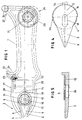
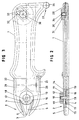
- the sharpening device on which the drawing is based consists of a handle Acting shaft-shaped support body 1, the one on the left in Figures 1 to 3 drawn end is provided with a sharpening head 2.
- a sharpening head 2 for this is the shaft-shaped Support body 1, as shown in Figures 1 and 3, with one in the longitudinal direction of the support body 1 extending, expanding inwards Provide edge indentation 3.
- a round, made of hard metal which acts as a sharpening tool
- Sharpening disc 4 is provided, which is perpendicular to the plane of the indentation 3 standing axis is arranged and accordingly parallel to the flat side of the support body 1 extends.
- the sharpening disc 4 is in the radial direction from one in the indentation 3rd protruding tongue 5 protrudes.
- the side flanks of the tongue 5 are of the Side flanks of the inwardly widening indentation 3 for formation lateral insertion slots 6 for each cutting tool to be sharpened spaced.
- the insertion slots 6 end on the inside on the circumference of the sharpening disc 4, the circumference of the insertion slots 6 at a comparatively acute angle cuts.
- the insertion slots 6 are used accordingly for sharpening Cutting tools with a comparatively acute cutting angle, such as knife blades.
- the angle between the side flanks of the tongue 5 is larger than the angle between the side edges of the indentation 3, so that the insertion slots expand to the outside, which facilitates handling and an adjustment of the Hold the tool to be sharpened at the desired cutting angle enables.
- the tongue 5 can, as indicated in FIG. 4 with broken lines, with a provided further insertion slot 8, which ends in the area of the sharpening disc 4.
- This further insertion slot 8 is expediently from the sharpening disc 4 under one comparatively obtuse angle cut and can therefore be used to sharpen Cutting with appropriate cutting angle, for example scissors, use Find.
- the arrangement of the insertion slot 8 can be chosen so that the Cutting angle between the insertion slot 8 and the sharpening disc 4 the usual Corresponds to the cutting angle of scissor knives.
- the Insertion slot 8 expediently obliquely to through the axis of the sharpening disk 4th going central longitudinal axis of the device.
- the angle can thus be varied in the direction of the central longitudinal axis.
- To the inside End of the insertion slot 8 can be a not shown, transversely to this Connect the running cross slot. This can have a certain elasticity Tongue 5 effect.
- the transverse slot can be approximately concentric to the center of the Sharpening disc 4 run.
- the tool to be sharpened is inserted into one of the insertion slots and with its cutting edge along the upper edge of the circumference of the sharpening disc 4 drawn. This results in a sharpening by a cutting machine Peeling process.
- the side flanks of the can easily tilt the cutting tool Edge indentation 3 with at least in the area of the underside of the supporting body 1 Phase 7 provided, as can best be seen from Figure 3.
- the sharpening disc 4 can have a sharp peeling edge, as best shown in FIG. 5 is recognizable, be conically narrowing downward. It turns out an angle of inclination of 3 ° - 6 ° is appropriate. This makes one corresponding clearance angle, which intensifies the peeling process.
- the sharpening disc is conical over its entire thickness and therefore cannot be turned. However, it would also be easily conceivable for the sharpening disc 4 to be provided with a V-shaped cross-section on the edges so that a would be possible.
- the sharpening disc 4 is arranged rotatable about its central axis. This will achieved that the entire circumference of the sharpening disc 4 can be used as a sharpening edge is. During a sharpening process, the sharpening disc 4 is still below by means of a fixture described in more detail fixed. As soon as the insertion slot 6 or 8 assigned peripheral area of the sharpening disc 4, the Clamping device opened and the sharpening disc 4 slightly turned. Then the tensioning device is tightened again. This process can be repeated until the entire circumference of the sharpening disc 4 has been used up. This results in a long total service life of the sharpening disc 4.
- the sharpening disc 4 is in an associated, open towards the indentation 3 Countersink 15 of the support body 1 inserted. This is through the sharpening wheel 4 receiving support areas 16 limited at the bottom.
- the depression 15 is how FIG. 1 shows a groove running in the longitudinal direction of the support body 1, which merges into the edge indentation. The clear width of this groove corresponds to that Diameter of the sharpening disc 4. The length of the groove mentioned is greater.
- the sharpening disc 4 can be in the longitudinal direction of the Support body can be adjusted. By moving the sharpening disc 4, the Angle at which the sharpening disc 4 cuts the insertion slots 6 and 8, change. The further the sharpening disc is moved forward, the duller it becomes this angle. This means that an exact adjustment of the sharpening geometry is required the geometry of the blade to be sharpened is possible.
- the support areas receiving the sharpening disc 4 are, as can best be seen from FIGS. 2 and 3, a the side Prongs of the sharpening head 2 in the area of the inner end of the indentation 3 bridging support web 16 and out of this, to the tines molded, lateral support strips 16a provided.
- the Sharpening wheel 4 in the innermost position.
- the sharpening disc 4 is in this position flat on the web 16 on only the front edge of the sharpening disc 4 free, i.e. not supported, so that a peeling process is not hindered.
- the web 16 has a parallel to the circumference of the sharpening disc 4 trending, i.e. outward convex front margin. If the sharpening disc 4 is advanced somewhat for the purpose of the angle adjustment mentioned above, it overhangs the web 16 more, whereby they face each other Edge areas are supported on the support strips 16a adjoining the web 16 becomes.
- the tongue 5 facing circumferential half of the plate 12 has a diameter of Sharpening disc 4 exceeding diameter, making the associated Circumferential area of the sharpening disc 4 is protected. In the transition area between The different diameter ranges accordingly result in a Figure 4 clearly illustrated stage 13.
- the plate 12 and with it the tongue 5 are by means of those already mentioned above Clamping device together with the sharpening disc 4 in relation to the supporting body 1 tense.
- the tensioning device has a cap screw 10, the web-side, the sharpening disc 4 receiving web 16, the Sharpening disc 4 and the plate 12 placed thereon and bearing the tongue 5 reaches through.
- the head screw 10 lies with its head on the web 16, that is Support body 1, and on the other hand cooperates with a knurled nut 11, the comes to rest on the plate 12.
- the head of the cap screw 10 is, as can be seen in FIG Support body 1 sunk that none over the flat underside of the support body 1 protruding edge results. It is therefore ensured that the support body 1 with its flat underside can be placed flat on a table, whereby only the sharpening head 2 protrudes so far that a cutting tool to be sharpened inserted into one of the insertion slots 6 and 8 and on the sharpening disk 4 can be deducted.
- the through a hole in the sharpening 4th continuous cap screw 10 associated recesses of the fixed Parts designed as elongated holes or grooves.
- the web 16 is sunk with one arranged head of the cap screw 10 receiving longitudinal groove 17 and with a provided by the shaft of the cap screw 10 elongated hole 18. If the Tongue 5 and, accordingly, the plate 12 carrying this, as shown in FIG Example are fixed, the plate 12 also has a corresponding elongated hole 18.
- the adjustment path of the warping disc 4 is determined by the length of the grooves or Elongated holes limited.
- the tongue 5 is fixed in the example shown, as mentioned above arranged, i.e. in contrast to the sharpening disc 4, it cannot be rotated and not slidable.
- the plate 12 is on its tongue 5 facing circumferential area with a behind the sharpening disc 4 Bolt 14 provided, the backlash in an assigned, supporting body side Holding recess 19 engages.
- the Halteausnehumung 19 be formed as a longitudinal groove.
- FIG. 1 Side flanks 20 of the support body 1 are provided in FIG which further sharpening devices, for example a bar-shaped pulling steel 21 or a polishing stone 22, etc. can be arranged. These sharpening tools are On the side facing away from the sharpening head 2, contact surfaces are assigned.
- the starting area assigned to the pull-off steel 21 as pivotable stop 23 which can be fixed by means of a clamping screw, its angle of inclination with respect to the assigned surface of the puller steel 21 is adjustable, as indicated by an angle scale 24.
- the stop 23 is from a web 25 can be swiveled, which acts as a finger system and slip protection.
- the opposite polishing stone 22 can be assigned a fixed contact surface.
- FIG. 1 In the area of the end of the support body 1 opposite the sharpening head 2 further sharpening devices can be provided.
- this end of the support body 1 with two Provide cutting devices, namely with a rotatable scoring roller 26 having glass cutter 27 and a rotating knife 28 Cutting device 29 for wallpapers etc.
- the rotatable knife 28 is of the type shown in FIG 1 shown with solid lines, sunk in the support body 1, inactive Position in the indicated by broken lines in Figure 1, from the Support body 1 extended, active position movable and vice versa.
- a tensioning device is provided which has a continuous cap screw 30 and has a knurled nut 31 cooperating therewith, as best shown in FIG 2 is recognizable. As shown in FIG.
- the head of the cap screw 30 is in one assigned groove 32 inserted, which is not overlooked.
- the head screw shaft 10 passes through an associated elongated hole 33.
- the rotating knife 26 is, like FIG 2 shows on a disc with a suitable collar 34 added.
- the knurled nut 31 bears against these in such a way that one of them Knives 28 associated, circumferential groove, so that this is rotatable.
Landscapes
- Engineering & Computer Science (AREA)
- Mechanical Engineering (AREA)
- Finish Polishing, Edge Sharpening, And Grinding By Specific Grinding Devices (AREA)
- Treatment Of Fiber Materials (AREA)
- Food-Manufacturing Devices (AREA)
Applications Claiming Priority (2)
| Application Number | Priority Date | Filing Date | Title |
|---|---|---|---|
| DE19841494A DE19841494C2 (de) | 1998-09-10 | 1998-09-10 | Vorrichtung zum manuellen Schärfen von Schneidwerkzeugen |
| DE19841494 | 1998-09-10 |
Publications (3)
| Publication Number | Publication Date |
|---|---|
| EP0985497A2 true EP0985497A2 (fr) | 2000-03-15 |
| EP0985497A3 EP0985497A3 (fr) | 2001-06-06 |
| EP0985497B1 EP0985497B1 (fr) | 2003-10-01 |
Family
ID=7880562
Family Applications (1)
| Application Number | Title | Priority Date | Filing Date |
|---|---|---|---|
| EP99116272A Expired - Lifetime EP0985497B1 (fr) | 1998-09-10 | 1999-08-18 | Dispositif d'affutage manuel d'outils de coupe |
Country Status (4)
| Country | Link |
|---|---|
| US (1) | US6237443B1 (fr) |
| EP (1) | EP0985497B1 (fr) |
| AT (1) | ATE251012T1 (fr) |
| DE (2) | DE19841494C2 (fr) |
Families Citing this family (1)
| Publication number | Priority date | Publication date | Assignee | Title |
|---|---|---|---|---|
| US7083268B2 (en) * | 2003-10-15 | 2006-08-01 | Hewlett-Packard Development Company, L.P. | Slotted substrates and methods of making |
Family Cites Families (5)
| Publication number | Priority date | Publication date | Assignee | Title |
|---|---|---|---|---|
| US1573875A (en) * | 1924-08-21 | 1926-02-23 | James E Shaw | Knife sharpener |
| US2186715A (en) * | 1937-12-31 | 1940-01-09 | Katzinger Edward Co | Knife sharpener |
| US2438681A (en) * | 1947-09-08 | 1948-03-30 | Jay R Reese | Knife sharpener |
| US2778249A (en) * | 1955-05-12 | 1957-01-22 | Herbert L Roberts | Sharpening device |
| DE29704759U1 (de) * | 1997-02-01 | 1997-06-05 | Liedschreiber, Karl, 86647 Buttenwiesen | Vorrichtung zum manuellen Schärfen von Schneidkanten von Schneidwerkzeugen |
-
1998
- 1998-09-10 DE DE19841494A patent/DE19841494C2/de not_active Expired - Fee Related
-
1999
- 1999-08-04 US US09/366,209 patent/US6237443B1/en not_active Expired - Fee Related
- 1999-08-18 DE DE59907169T patent/DE59907169D1/de not_active Expired - Fee Related
- 1999-08-18 AT AT99116272T patent/ATE251012T1/de not_active IP Right Cessation
- 1999-08-18 EP EP99116272A patent/EP0985497B1/fr not_active Expired - Lifetime
Also Published As
| Publication number | Publication date |
|---|---|
| ATE251012T1 (de) | 2003-10-15 |
| DE19841494C2 (de) | 2002-12-12 |
| EP0985497B1 (fr) | 2003-10-01 |
| US6237443B1 (en) | 2001-05-29 |
| DE19841494A1 (de) | 2000-03-23 |
| DE59907169D1 (de) | 2003-11-06 |
| EP0985497A3 (fr) | 2001-06-06 |
Similar Documents
| Publication | Publication Date | Title |
|---|---|---|
| DE3722478A1 (de) | Fraeswerkzeug | |
| DE8200527U1 (de) | Eckenschere | |
| DE2250265B2 (de) | Handwerkzeug zum Entgraten und Schaben | |
| EP2370235B1 (fr) | Mandoline | |
| EP2200775A1 (fr) | Alésoir | |
| DE3316053C2 (fr) | ||
| EP0985497B1 (fr) | Dispositif d'affutage manuel d'outils de coupe | |
| EP4536434B1 (fr) | Dispositif de guidage d'outil lors de la coupe d'une pièce à travailler | |
| WO2009030454A1 (fr) | Alésoir | |
| DE3233682A1 (de) | Skikantenschaerfer | |
| DE2503677A1 (de) | Spanabhebendes werkzeug | |
| DE10300972A1 (de) | Schleifvorrichtung für rotierend angetriebene Kreismesser | |
| DE19703807C1 (de) | Vorrichtung zum manuellen Schärfen von Schneidkanten von Schneidwerkzeugen | |
| DE3604477A1 (de) | Rohkost-zerkleinerungsgeraet | |
| EP1245352A1 (fr) | Rabot refendeur à main destiné aux courroies | |
| DE2647331A1 (de) | Geraet zum schneiden von fliesen aus fayence, steingut oder anderem keramischen material | |
| DE102021123535A1 (de) | Schneidlade und/oder Schmiege | |
| DE102021123534A1 (de) | Schneidlade und/oder Schmiege | |
| DE1950037C3 (de) | Schneidwerkzeug für die spanabhebende Bearbeitung | |
| AT397629B (de) | Einrichtung zur messerbefestigung an umlaufenden hackscheiben von (holzspan)-hackmaschinen sowie (einweg-)hackmesser hiefür | |
| DE19833127C1 (de) | Messerkopf | |
| DE102022111939B3 (de) | Messerwalze für eine Vorrichtung zum Zerkleinern von Gefriergut | |
| DE9108553U1 (de) | Messerkopf, insbesondere Hobelkopf | |
| DE8525144U1 (de) | Rohkost-Zerkleinerungsgerät | |
| DE8204890U1 (de) | Skikantenhobel |
Legal Events
| Date | Code | Title | Description |
|---|---|---|---|
| PUAI | Public reference made under article 153(3) epc to a published international application that has entered the european phase |
Free format text: ORIGINAL CODE: 0009012 |
|
| AK | Designated contracting states |
Kind code of ref document: A2 Designated state(s): AT BE CH CY DE DK ES FI FR GB GR IE IT LI LU MC NL PT SE |
|
| AX | Request for extension of the european patent |
Free format text: AL;LT;LV;MK;RO;SI |
|
| PUAL | Search report despatched |
Free format text: ORIGINAL CODE: 0009013 |
|
| AK | Designated contracting states |
Kind code of ref document: A3 Designated state(s): AT BE CH CY DE DK ES FI FR GB GR IE IT LI LU MC NL PT SE |
|
| AX | Request for extension of the european patent |
Free format text: AL;LT;LV;MK;RO;SI |
|
| 17P | Request for examination filed |
Effective date: 20010628 |
|
| AKX | Designation fees paid |
Free format text: AT BE CH CY DE DK ES FI FR GB GR IE IT LI LU MC NL PT SE |
|
| 17Q | First examination report despatched |
Effective date: 20020507 |
|
| GRAH | Despatch of communication of intention to grant a patent |
Free format text: ORIGINAL CODE: EPIDOS IGRA |
|
| GRAS | Grant fee paid |
Free format text: ORIGINAL CODE: EPIDOSNIGR3 |
|
| GRAA | (expected) grant |
Free format text: ORIGINAL CODE: 0009210 |
|
| AK | Designated contracting states |
Kind code of ref document: B1 Designated state(s): AT BE CH CY DE DK ES FI FR GB GR IE IT LI LU MC NL PT SE |
|
| PG25 | Lapsed in a contracting state [announced via postgrant information from national office to epo] |
Ref country code: NL Free format text: LAPSE BECAUSE OF FAILURE TO SUBMIT A TRANSLATION OF THE DESCRIPTION OR TO PAY THE FEE WITHIN THE PRESCRIBED TIME-LIMIT Effective date: 20031001 Ref country code: IT Free format text: LAPSE BECAUSE OF FAILURE TO SUBMIT A TRANSLATION OF THE DESCRIPTION OR TO PAY THE FEE WITHIN THE PRESCRIBED TIME-LIMIT;WARNING: LAPSES OF ITALIAN PATENTS WITH EFFECTIVE DATE BEFORE 2007 MAY HAVE OCCURRED AT ANY TIME BEFORE 2007. THE CORRECT EFFECTIVE DATE MAY BE DIFFERENT FROM THE ONE RECORDED. Effective date: 20031001 Ref country code: IE Free format text: LAPSE BECAUSE OF FAILURE TO SUBMIT A TRANSLATION OF THE DESCRIPTION OR TO PAY THE FEE WITHIN THE PRESCRIBED TIME-LIMIT Effective date: 20031001 Ref country code: GB Free format text: LAPSE BECAUSE OF FAILURE TO SUBMIT A TRANSLATION OF THE DESCRIPTION OR TO PAY THE FEE WITHIN THE PRESCRIBED TIME-LIMIT Effective date: 20031001 Ref country code: FR Free format text: LAPSE BECAUSE OF FAILURE TO SUBMIT A TRANSLATION OF THE DESCRIPTION OR TO PAY THE FEE WITHIN THE PRESCRIBED TIME-LIMIT Effective date: 20031001 Ref country code: FI Free format text: LAPSE BECAUSE OF FAILURE TO SUBMIT A TRANSLATION OF THE DESCRIPTION OR TO PAY THE FEE WITHIN THE PRESCRIBED TIME-LIMIT Effective date: 20031001 Ref country code: CY Free format text: LAPSE BECAUSE OF FAILURE TO SUBMIT A TRANSLATION OF THE DESCRIPTION OR TO PAY THE FEE WITHIN THE PRESCRIBED TIME-LIMIT Effective date: 20031001 |
|
| REG | Reference to a national code |
Ref country code: GB Ref legal event code: FG4D Free format text: NOT ENGLISH |
|
| REG | Reference to a national code |
Ref country code: CH Ref legal event code: EP |
|
| REG | Reference to a national code |
Ref country code: IE Ref legal event code: FG4D Free format text: GERMAN |
|
| REF | Corresponds to: |
Ref document number: 59907169 Country of ref document: DE Date of ref document: 20031106 Kind code of ref document: P |
|
| REG | Reference to a national code |
Ref country code: CH Ref legal event code: NV Representative=s name: ROTTMANN, ZIMMERMANN + PARTNER AG |
|
| PG25 | Lapsed in a contracting state [announced via postgrant information from national office to epo] |
Ref country code: SE Free format text: LAPSE BECAUSE OF FAILURE TO SUBMIT A TRANSLATION OF THE DESCRIPTION OR TO PAY THE FEE WITHIN THE PRESCRIBED TIME-LIMIT Effective date: 20040101 Ref country code: GR Free format text: LAPSE BECAUSE OF FAILURE TO SUBMIT A TRANSLATION OF THE DESCRIPTION OR TO PAY THE FEE WITHIN THE PRESCRIBED TIME-LIMIT Effective date: 20040101 Ref country code: DK Free format text: LAPSE BECAUSE OF FAILURE TO SUBMIT A TRANSLATION OF THE DESCRIPTION OR TO PAY THE FEE WITHIN THE PRESCRIBED TIME-LIMIT Effective date: 20040101 |
|
| PG25 | Lapsed in a contracting state [announced via postgrant information from national office to epo] |
Ref country code: ES Free format text: LAPSE BECAUSE OF FAILURE TO SUBMIT A TRANSLATION OF THE DESCRIPTION OR TO PAY THE FEE WITHIN THE PRESCRIBED TIME-LIMIT Effective date: 20040112 |
|
| NLV1 | Nl: lapsed or annulled due to failure to fulfill the requirements of art. 29p and 29m of the patents act | ||
| GBV | Gb: ep patent (uk) treated as always having been void in accordance with gb section 77(7)/1977 [no translation filed] |
Effective date: 20031001 |
|
| REG | Reference to a national code |
Ref country code: IE Ref legal event code: FD4D |
|
| PLBE | No opposition filed within time limit |
Free format text: ORIGINAL CODE: 0009261 |
|
| STAA | Information on the status of an ep patent application or granted ep patent |
Free format text: STATUS: NO OPPOSITION FILED WITHIN TIME LIMIT |
|
| PG25 | Lapsed in a contracting state [announced via postgrant information from national office to epo] |
Ref country code: LU Free format text: LAPSE BECAUSE OF NON-PAYMENT OF DUE FEES Effective date: 20040818 |
|
| PG25 | Lapsed in a contracting state [announced via postgrant information from national office to epo] |
Ref country code: MC Free format text: LAPSE BECAUSE OF NON-PAYMENT OF DUE FEES Effective date: 20040831 Ref country code: BE Free format text: LAPSE BECAUSE OF NON-PAYMENT OF DUE FEES Effective date: 20040831 |
|
| 26N | No opposition filed |
Effective date: 20040702 |
|
| EN | Fr: translation not filed | ||
| BERE | Be: lapsed |
Owner name: *LIEDSCHREIBER KARL Effective date: 20040831 |
|
| PGFP | Annual fee paid to national office [announced via postgrant information from national office to epo] |
Ref country code: CH Payment date: 20070827 Year of fee payment: 9 Ref country code: AT Payment date: 20070822 Year of fee payment: 9 |
|
| BERE | Be: lapsed |
Owner name: *LIEDSCHREIBER KARL Effective date: 20040831 |
|
| PG25 | Lapsed in a contracting state [announced via postgrant information from national office to epo] |
Ref country code: PT Free format text: LAPSE BECAUSE OF NON-PAYMENT OF DUE FEES Effective date: 20040301 |
|
| PGFP | Annual fee paid to national office [announced via postgrant information from national office to epo] |
Ref country code: DE Payment date: 20071029 Year of fee payment: 9 |
|
| REG | Reference to a national code |
Ref country code: CH Ref legal event code: PL |
|
| PG25 | Lapsed in a contracting state [announced via postgrant information from national office to epo] |
Ref country code: AT Free format text: LAPSE BECAUSE OF NON-PAYMENT OF DUE FEES Effective date: 20080818 |
|
| PG25 | Lapsed in a contracting state [announced via postgrant information from national office to epo] |
Ref country code: LI Free format text: LAPSE BECAUSE OF NON-PAYMENT OF DUE FEES Effective date: 20080831 Ref country code: CH Free format text: LAPSE BECAUSE OF NON-PAYMENT OF DUE FEES Effective date: 20080831 |
|
| PG25 | Lapsed in a contracting state [announced via postgrant information from national office to epo] |
Ref country code: DE Free format text: LAPSE BECAUSE OF NON-PAYMENT OF DUE FEES Effective date: 20090303 |