EP0985512A2 - Kunststoff-Spritzgiessmaschine sowie Verfahren zum Steuern einer solchen - Google Patents
Kunststoff-Spritzgiessmaschine sowie Verfahren zum Steuern einer solchen Download PDFInfo
- Publication number
- EP0985512A2 EP0985512A2 EP99115574A EP99115574A EP0985512A2 EP 0985512 A2 EP0985512 A2 EP 0985512A2 EP 99115574 A EP99115574 A EP 99115574A EP 99115574 A EP99115574 A EP 99115574A EP 0985512 A2 EP0985512 A2 EP 0985512A2
- Authority
- EP
- European Patent Office
- Prior art keywords
- gripping tool
- path
- acceleration
- tool
- maximum
- Prior art date
- Legal status (The legal status is an assumption and is not a legal conclusion. Google has not performed a legal analysis and makes no representation as to the accuracy of the status listed.)
- Withdrawn
Links
- 238000000034 method Methods 0.000 title claims abstract description 35
- 238000001746 injection moulding Methods 0.000 title claims abstract description 26
- 239000000463 material Substances 0.000 title description 3
- 238000000465 moulding Methods 0.000 claims abstract description 21
- 230000001133 acceleration Effects 0.000 claims description 51
- 230000002452 interceptive effect Effects 0.000 claims description 6
- 230000007423 decrease Effects 0.000 claims description 2
- 238000007493 shaping process Methods 0.000 claims 1
- 230000008901 benefit Effects 0.000 description 15
- 238000010586 diagram Methods 0.000 description 8
- 238000005265 energy consumption Methods 0.000 description 3
- 230000002123 temporal effect Effects 0.000 description 3
- 238000004519 manufacturing process Methods 0.000 description 2
- 238000010276 construction Methods 0.000 description 1
- 230000003111 delayed effect Effects 0.000 description 1
- 230000001066 destructive effect Effects 0.000 description 1
- 238000006073 displacement reaction Methods 0.000 description 1
- 238000005516 engineering process Methods 0.000 description 1
- 238000002347 injection Methods 0.000 description 1
- 239000007924 injection Substances 0.000 description 1
- 230000007774 longterm Effects 0.000 description 1
- 230000001960 triggered effect Effects 0.000 description 1
Images

Classifications
-
- B—PERFORMING OPERATIONS; TRANSPORTING
- B29—WORKING OF PLASTICS; WORKING OF SUBSTANCES IN A PLASTIC STATE IN GENERAL
- B29C—SHAPING OR JOINING OF PLASTICS; SHAPING OF MATERIAL IN A PLASTIC STATE, NOT OTHERWISE PROVIDED FOR; AFTER-TREATMENT OF THE SHAPED PRODUCTS, e.g. REPAIRING
- B29C45/00—Injection moulding, i.e. forcing the required volume of moulding material through a nozzle into a closed mould; Apparatus therefor
- B29C45/17—Component parts, details or accessories; Auxiliary operations
- B29C45/40—Removing or ejecting moulded articles
- B29C45/42—Removing or ejecting moulded articles using means movable from outside the mould between mould parts, e.g. robots
-
- B—PERFORMING OPERATIONS; TRANSPORTING
- B29—WORKING OF PLASTICS; WORKING OF SUBSTANCES IN A PLASTIC STATE IN GENERAL
- B29C—SHAPING OR JOINING OF PLASTICS; SHAPING OF MATERIAL IN A PLASTIC STATE, NOT OTHERWISE PROVIDED FOR; AFTER-TREATMENT OF THE SHAPED PRODUCTS, e.g. REPAIRING
- B29C45/00—Injection moulding, i.e. forcing the required volume of moulding material through a nozzle into a closed mould; Apparatus therefor
- B29C45/17—Component parts, details or accessories; Auxiliary operations
- B29C45/40—Removing or ejecting moulded articles
- B29C45/42—Removing or ejecting moulded articles using means movable from outside the mould between mould parts, e.g. robots
- B29C2045/4275—Related movements between the robot gripper and the movable mould or ejector
Definitions
- the present invention relates to a method for control a motion sequence of a plastic injection molding machine, the a mold with at least one movable mold and comprises a movable gripping tool, the gripping tool in an open position of the mold between at least two Forming tools can be retracted, which also includes the gripping tool facing side of the movable mold at their Movement an interference contour for the movement of the gripping tool defined and the gripping tool only then the interference contour happens when the movable mold is out of the path of motion of the gripping tool, by which method the gripping tool along a first path Maximum speed is accelerated and then along a second distance to a position between the molds is essentially braked to a standstill.
- the invention also relates to a plastic injection molding machine with a mold that has at least two molds comprises, at least one of which is a movable one Forming tool is, as well as with a gripping tool that in one open position of the mold retractable between the molds is, the side of the gripping tool facing movable mold during their movement an interference contour for defines the retracting movement of the gripping tool and furthermore the retracting movement of the gripping tool at a starting position begins in the direction of movement of the gripping tool the interference contour lies.
- a plastic injection molding machine includes one Form with at least one cavity in which by filling a initially a mouldable part or workpiece can be produced. It is then to remove the workpiece required to open the mold.
- the Mold usually consists of at least two molds, which in form the shape in an abutting state. At least one of the molds is along a first trajectory movable and can thereby by the other mold be lifted off. In this state the mold is open and a gripping tool can move between the molds, to remove the manufactured workpiece. How easy can be seen, these movements, i.e.
- the opening and closing movements of the mold and the retracting and extending movements of the gripping tool must be precisely coordinated to avoid collisions and consequent damage to the molds and to avoid the gripping tool. At the same time, they should However, movements as quickly as possible and with the least possible Delay times are run to be in the interest high cycle productivity of the machine to keep it as low as possible.
- control of the Gripping tool with maximum possible acceleration does not necessarily mean that the dwell time of the gripping tool is actually minimal within the opened form.
- the gripping tool is also controlled maximum acceleration to maximum load changes. This is with regard to the load on the bearings of the machine and thus disadvantageous in terms of wear.
- maximum speed is used in the following understood the speed at which the gripping tool maximally movable within a longer production cycle is. However, this speed can also go below the absolutely possible maximum speed if this does not enable non-destructive continuous operation of the machine. In this respect there is the fact that the gripping tool at a concrete machine moves slightly faster in individual cases than can actually be done in continuous operation, not contrary to the above invention.
- the inventor of the present invention has recognized that in With regard to a minimal dwell time of the gripping tool in the Area between the molds much more on the speed of the gripping tool when its acceleration is important.
- the two sizes are related to each other in a known manner together; however, if the distance along which the Gripping tool accelerates when it moves into the mold is too short, then the gripping tool its maximum speed despite maximum acceleration do not reach.
- the measure according to the invention ensures that Gripping tool with maximum speed in the area between the molds. This makes it possible reduce the length of stay to its minimum.
- the gripping tool from passing the interfering contour as long as possible with his Maximum speed moves and then preferably at maximum Decelerated so far that it is in the form Workpiece, i.e. preferably by Standstill. Subsequently, the gripping tool is preferred accelerated with the maximum acceleration and from the Extend the area between the molds.
- the Measure according to the invention after passing the interference contour time to use, for example, the gripping tool decelerate with a deceleration less than the maximum possible delay.
- the gripping tool does not reach maximum acceleration when moving out of the area to accelerate. In both cases it would be natural the dwell time of the gripping tool in the area not minimal.
- a maximum Deceleration or a maximum acceleration also a maximum Load on the bearings due to the extreme in this case Load changes and maximum power consumption of the drive motors, which lead to thermal problems in long-term operation can.
- the measure according to the invention has the advantage, on the one hand the dwell time of the gripping tool within the area to be minimal between the molds, if this is needed, but alternatively the wear and tear Energy consumption of a corresponding machine with the same To reduce the length of stay.
- the task is carried out on a plastic injection molding machine initially mentioned type further solved in that a first Distance of the gripping tool between the starting position and the interference contour is at least so long that the gripping tool along this first distance to a maximum speed is accelerable.
- Procedure ends the first path at the interference contour, so that the gripping tool the maximum speed when passing the interference contour is reached.
- the gripping tool in the area between the Molding tools up to the start of the second path with the Maximum speed moves and then along the second distance with a constant delay slowed down.
- This measure has the advantage that the gripping tool this way when moving in after passing the Interference contour as long as possible at its maximum speed is moved. In the sense of the above explanations this measure contributes to what is possible on the basis of the invention Realization of the minimum dwell time. Alternatively, as previously explained, it is however also conceivable, the one obtained when passing the interference contour To use time otherwise. Because of the measure mentioned here however, is the time between passing the interfering contour and reaching the position where the gripping tool the workpiece or molded part can accommodate, minimal.
- the gripping tool is moved along the first Distance with a constant maximum acceleration accelerates.
- This measure has the advantage that it is the first Distance is as short as possible. This in turn leads to a correspondingly designed plastic injection molding machine while maintaining by the invention overall advantages achieved can be built very short.
- the the feature mentioned here is particularly advantageous in combination with the first advantageous embodiment, according to which the first Path ends at the interference contour.
- Another advantage of this measure is that the machine's control program only an acceleration value instead of one acceleration profile consisting of several Values must be stored. This way you can save space save on.
- the length of the first distance greater than 10 cm is preferably in the range between 15 cm and 70 cm particularly preferably in the range between 20 cm and 40 cm.
- This measure has the advantage that, given the maximum accelerations of the gripping tool currently achievable of approx. 50 to 60 m / s 2 and the possible maximum speeds of approx. 5 to 6 m / s, it reliably implements the method according to the invention.
- the preferred size ranges also represent an advantageous compromise with regard to the required size of the machine.
- the gripping tool is first along a first section accelerated the first distance with a first acceleration and then along another section of the first path accelerated with a second acceleration, whereby the second acceleration is greater than the first acceleration.
- This measure takes advantage of the fact that the speed profile of the gripping tool before it passes the interference contour for the dwell time of the gripping tool inside of the area doesn't matter. It has the advantage that starting the gripping tool with an initially less acceleration, less load changes and thus a causes less wear. After starting the gripping tool the acceleration can then be increased to then in the sense of a short design of the machine the maximum speed to reach faster. In addition to the reduced in this way Load changes are also used to accelerate the gripping tool required energy consumption, lower.
- Another advantage of this measure is related with one always to be considered or possible Disruption of movement.
- a disturbance occurs For example, when the movable mold jams and accordingly its opening movement is delayed or even not executing. In this case, it is imperative that To stop movement of the gripping tool by an emergency stop to avoid a collision. Such disturbances often occur just at the beginning of each movement. If in this case according to the advantageous explained here Embodiment of the invention, the acceleration of the gripping tool is relatively small at the beginning, is just at the beginning the movement sequence more time for an emergency stop of the gripping tool to disposal. At the same time, in this case, too Less load changes in the event of an emergency stop.
- the second acceleration the maximum acceleration.
- the further section from which the gripping tool accelerates with the maximum acceleration is started at the position from which an emergency stop of the gripping tool can no longer prevent a collision. This is then the case when the gripping tool due to its inertia can no longer be braked without passing through the interference contour. This is due to the configuration mentioned here last section as short as possible and will be as quick as possible to go through.
- the gripping tool is first extended with the Maximum acceleration accelerated to the maximum speed and then at least as long as possible at maximum speed moves until it's the area between the dies has left.
- This measure has the advantage that the residence time of the Gripping tool in the area between the molds too is minimized as much as possible during the extension movement. As a result, this measure is advantageous if the length of stay of the gripping tool actually within the area their minimum value should be reduced.
- the gripping tool is left after leaving the area between the molds braked with a delay that is less is than the maximum deceleration.
- This measure in turn has the advantage that it is less Load changes and accordingly the bearings of the Gripping tool less stressed. This reduces wear.
- the retraction of the gripping tool is already timed started before or during the opening movement of the mold.
- This measure has the advantage that the invention Method with the methods for overlapping which are already known per se the movements of the gripping tool and the molding tools is combined. Only through such a combination the cycle time of the Injection molding machine can be minimized.
- 1 to 3 is a schematically illustrated plastic injection molding machine overall according to the present invention designated by the reference number 10.
- the plastic injection molding machine 10 includes a mold 12 as well a gripping tool 14. It is for the present invention irrelevant whether the gripping tool 14 is part of a own handling device or part of the plastic injection molding machine itself is.
- the mold 12 comprises two molds 16, 17, in the illustration in Fig. 1 to each other apply and thereby form a cavity 18 in which Filling in an initially still formable and later hardening Material a workpiece 20 can be produced. First of all malleable material becomes the cavity via a channel 22 18 fed.
- the molding tool 16 is in capable of opening and closing movement 24 along one Execute the axis designated as the Y axis.
- the molds 16 and 17 have the gripping tool on them 14 facing side an edge or surface 28, 30.
- the Edge 28 of the movable mold 16 defines one Interference contour 32 for the movement of the gripping tool 14. With the Passing the interference contour 32, the gripping tool 14 gets into the Area 34 between the molds 16 and 17.
- the retraction or extension movement 36 of the gripping tool 14 takes place along an X axis, which in the present exemplary embodiment perpendicular to the Y axis of the opening and closing movement 24 lies. However, this is not absolutely necessary.
- the gripping tool 14 moves into the mold 12 starting from an initial position S 0 .
- the initial speed of the gripping tool 14 is designated V 0 .
- the movable molding tool 16 is moved in the direction of the Y axis, whereby the mold 12 is opened.
- the movements of the gripping tool 14 and the movable molding tool 16 are thus at least partially overlapping. It is sufficient here that the movable molding tool 16 has moved just so far at the moment when the gripping tool 14 passes the interference contour 32 that the gripping tool 14 fits past the edge 28 of the molding tool 16.
- FIG. 2 shows the moment at which the gripping tool 14 passes the interfering contour 32, which is identified by the position S 1 on the X axis. At this moment, the gripping tool 14 has the speed V 1 . The gripping tool 14 is accelerated to this speed along the path from S 0 to S 1 .
- edge 28 opposes the version shown here can also be rounded or, for example, can have a recess on the basis of which the Gripping tool 14 even closer to the movable molding tool 16 can be brought up yourself.
- the movable mold 16 is in its open end position.
- the gripping tool 14 has reached a position S 2 , at which it picks up the workpiece 20 produced from the mold 12.
- the molding tool 17 is provided with ejectors, not shown here, which push the workpiece 20 out of the cavity 18. These ejectors are coordinated with the movement of the gripping tool 14.
- the gripping tool 14 After picking up the workpiece 20, the gripping tool 14 in the embodiment shown here backwards from the Form 12 pulled out. Simultaneously or in a corresponding manner temporal coordination becomes the movable mold 16 move again in the direction of the mold 17 to the Close mold 12 for the next manufacturing process.
- the Coordination of the movements of the gripping tool 14 and the Movable mold 16 takes place, for example release signals mentioned at the beginning.
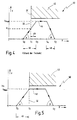
- FIG. 4 is a speed-distance diagram for explanation the movement of the gripping tool 14 as a whole with the Reference numeral 40 denotes.
- the positions of the gripping tool 14, which are already shown in FIGS. 1 to 3, are indicated along the X axis.
- the position of the mold 17 is indicated schematically by 42.
- the interference contour 32 is located at position S 1 .
- the course of the speed of the gripping tool 14 during its retracting movement is designated by 44.
- the course 44 represents a method according to the prior art.
- the gripping tool 14 is accelerated from the starting position S 0 along a first path 46. Accordingly, its speed increases along the path 46.
- the acceleration of the gripping tool 14 in this case is not directly differentiated of the course 44 results, since the course 44 is not here a temporal, but a spatial speed curve is. Nevertheless, the slope of the course 44 is also in this representation is a measure of the respective acceleration.
- the gripping tool 14 is accelerated to its maximum speed V max along the first path 46 with constant acceleration, which here corresponds to the maximum acceleration.
- the angle ⁇ drawn in the illustration is a measure of the maximum acceleration.
- the speed at the moment when the gripping tool 14 passes the interference contour 32 is denoted by V 1 . As can be seen from the course, it is lower than the maximum speed V max .
- the gripping tool 14 is braked starting at position S 4 along the second path 48 until it stops at position S 2 .
- the delay for which the angle ⁇ is a measure is the maximum delay.
- the maximum acceleration ( ⁇ ) and the maximum deceleration ( ⁇ ) are not necessarily identical in terms of amount, which results from the fact that the deceleration is achieved differently from the acceleration in terms of technology and design. In the present case, the amount of the maximum deceleration ( ⁇ ) is greater than the maximum acceleration ( ⁇ ).
- the gripping tool 14 In the area between the first path 46 and the second path 48, the gripping tool 14 is moved at its maximum speed V max .
- V max the maximum speed
- the distances 46 and 48 and the size of the area between the molds 16 and 17 are dimensioned such that the speed profile 44 assumes a triangular profile, that is to say that the acceleration phase along the distance 46 directly affects the deceleration phase along the Route 48 connects.
- a disadvantage of this known speed profile 44 is section 49 of path 46. This section begins at position S 1 , at which gripping tool 14 passes interference contour 32, and extends to position S 3 , at which gripping tool 14 reaches its maximum speed V max reached. Along this section 49, the gripping tool 14 is already moving within the area 34, but not yet at the maximum possible speed V max . Accordingly, valuable time is wasted here.
- FIG. 5 is a speed-displacement diagram according to the invention generally designated by the reference number 50. Same Reference symbols denote the same elements that already exist were explained in relation to the previous figures.
- the gripping tool 14 is again accelerated to its maximum speed V max along the first path 46, the first path 46 being dimensioned here, however, such that the gripping tool 14 reaches the maximum speed V max at the position S 1 .
- the gripping tool 14 already passes the interference contour at its maximum speed V max .
- the starting point S 0 ' which marks the beginning of the path 46 here, is consequently further away from the interference contour 32 than the starting point S 0 in FIG. 4.
- the gripping tool 14 moves longer with its maximum speed V max within the area 34 in the method according to the invention. Accordingly, the average speed reached within the area 34 is greater under otherwise identical conditions than with the course in FIG. 4. As a result, the dwell time of the gripping tool 14 within the area 34 is shorter than with the course 44.
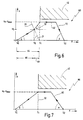
- a speed-distance diagram is designated as a whole by reference number 60.
- the speed profile 62 here corresponds to the speed profile 52 from position S 1 , at which the gripping tool 14 passes the interference contour 32.
- the profile 62 differs from the profile 52 before passing the interference contour 32 in the manner described below.
- the gripping tool 14 is accelerated along a first distance 64 starting from an initial position S 0 ′′ to its maximum speed. In this case, too, the maximum speed is reached at the moment when the gripping tool 14 passes the interference contour 32. In contrast to the previous exemplary embodiment, however, the gripping tool 14 is accelerated along a first section 66 of the first path 64 with an acceleration ( ⁇ ) which is less than the maximum acceleration ( ⁇ ).
- the first section 66 ends at a position S 5 .
- a further section 68 of the first path 64 begins at this position.
- the gripping tool 14 is accelerated with the maximum acceleration ( ⁇ ).
- the length of the further section 68 corresponds precisely to the shortest braking distance of the gripping tool 14 from its speed reached at the beginning of this section. This is illustrated by the straight line 70 along which the speed runs in the event of braking with maximum deceleration ( ⁇ ).
- the position S 5 is the position at which an emergency stop must be triggered at the latest in order to bring the gripping tool 14 to a stop before it passes the interference contour.
- FIG. 7 shows a further speed-distance diagram with designated by the reference numeral 80.
- the speed curve illustrates this 82, as the gripping tool 14 after the Retract the workpiece 20 out of the mold 12 again becomes.
- the gripping tool 14 in this case is accelerated from its end position S 2 with the maximum acceleration ( ⁇ ) to its maximum speed V max and then moved at the maximum speed V max until it passes the interference contour 32 again and thereby the area 34 leaves. From this point S 1 , the gripping tool 14 is braked with a deceleration ( ⁇ ) that is less than the maximum possible deceleration ( ⁇ ).
- the delay ( ⁇ ) in the present case is such that the gripping tool 14 comes to a standstill at the position S 0 ′′.
- the first distance is dimensioned in connection with the acceleration taking place there in such a way that the gripping tool 14 does not reach its maximum speed V max until the interference contour 32 is reached, but before that, ie before reaching the position S 1 assumes.
- the invention is also applicable to a plastic injection molding machine can be used with a stack tool as they are is described for example in EP 0 576 837.
Landscapes
- Engineering & Computer Science (AREA)
- Robotics (AREA)
- Manufacturing & Machinery (AREA)
- Mechanical Engineering (AREA)
- Injection Moulding Of Plastics Or The Like (AREA)
- Moulds For Moulding Plastics Or The Like (AREA)
Abstract
Description
- Fig. 1
- eine schematische Darstellung einer erfindungsgemäßen Kunststoff-Spritzgießmaschine mit geschlossenen Formwerkzeugen und einem Greifwerkzeug,
- Fig. 2
- die Kunststoff-Spritzgießmaschine aus Fig. 1 mit teilweise geöffneten Formwerkzeugen,
- Fig. 3
- die Kunststoff-Spritzgießmaschine mit vollständig geöffneten Formwerkzeugen,
- Fig. 4
- ein Geschwindigkeits-Weg-Diagramm, das die Einfahrbewegung des Greifwerkzeugs bei einer Kunststoff-Spritzgießmaschine nach dem Stand der Technik verdeutlicht,
- Fig. 5
- ein Geschwindigkeits-Weg-Diagramm für das Greifwerkzeug nach dem erfindungsgemäßen Verfahren,
- Fig. 6
- ein Geschwindigkeits-Weg-Diagramm eines alternativen Ausführungsbeispiels des erfindungsgemäßen Verfahrens und
- Fig. 7
- ein Geschwindigkeits-Weg-Diagramm für die Ausfahrbewegung des Greifwerkzeugs.
Claims (14)
- Verfahren zum Steuern eines Bewegungsablaufs einer Kunststoff-Spritzgießmaschine (10), die eine Form (12) mit mindestens einem bewegbaren Formwerkzeug (16) sowie ein bewegbares Greifwerkzeug (14) umfaßt, wobei das Greifwerkzeug (14) in einer geöffneten Stellung der Form (12) zwischen wenigstens zwei Formwerkzeuge (16, 17) einfahrbar ist, wobei ferner die zu dem Greifwerkzeug (14) weisende Seite des bewegbaren Formwerkzeugs (16) bei ihrer Bewegung eine Störkontur (32) für die Bewegung des Greifwerkzeugs (14) definiert und wobei das Greifwerkzeug (14) die Störkontur (32) erst dann passiert, wenn das bewegbare Formwerkzeug (16) sich aus der Bewegungsbahn des Greifwerkzeugs (14) entfernt hat, bei welchem Verfahren das Greifwerkzeug (14) entlang einer ersten Wegstrecke (46; 64) auf eine Maximalgeschwindigkeit (Vmax) beschleunigt wird und dann entlang einer zweiten Wegstrecke (48) bis zu einer Position (S2) zwischen den Formwerkzeugen (16, 17) im wesentlichen bis zum Stillstand abgebremst wird, dadurch gekennzeichnet, daß das Greifwerkzeug (14) die erste Wegstrecke (46; 64) vor dem Passieren der Störkontur (32) durchläuft, so daß es beim Passieren der Störkontur (32) im wesentlichen mit der Maximalgeschwindigkeit (vmax) bewegt wird.
- Verfahren nach Anspruch 1, dadurch gekennzeichnet, daß die erste Wegstrecke (46; 64) an der Störkontur (32) endet, so daß das Greifwerkzeug (14) die Maximalgeschwindigkeit (vmax) in etwa beim Passieren der Störkontur (32) erreicht.
- Verfahren nach Anspruch 1 oder 2, dadurch gekennzeichnet, daß das Greifwerkzeug (14) in einem Bereich (34) zwischen den Formwerkzeugen (16, 17) bis zum Beginn der zweiten Wegstrecke (48) mit der Maximalgeschwindigkeit (vmax) bewegt und daran anschließend entlang der zweiten Wegstrecke (48) mit einer gleichbleibenden Verzögerung (β) abgebremst wird.
- Verfahren nach einem der Ansprüche 1 bis 3, dadurch gekennzeichnet, daß das Greifwerkzeug (14) entlang der ersten Wegstrecke (46) mit einer gleichbleibenden Maximalbeschleunigung (α) beschleunigt wird.
- Verfahren nach Anspruch 4, dadurch gekennzeichnet, daß die Länge der ersten Wegstrecke (46) größer ist als 10 cm, vorzugsweise im Bereich zwischen 15 cm und 70 cm und besonders bevorzugt im Bereich zwischen 20 cm und 40 cm liegt.
- Verfahren nach einem der Ansprüche 1 bis 3, dadurch gekennzeichnet, daß das Greifwerkzeug (14) zunächst entlang eines ersten Abschnitts (66) der ersten Wegstrecke (64) mit einer ersten Beschleunigung (γ) und dann entlang eines weiteren Abschnitts (68) der ersten Wegstrecke (64) mit einer zweiten Beschleunigung (α) beschleunigt wird, wobei die zweite Beschleunigung (α) größer ist als die erste Beschleunigung (γ).
- Verfahren nach Anspruch 6, dadurch gekennzeichnet, daß die zweite Beschleunigung (α) die Maximalbeschleunigung ist.
- Verfahren nach Anspruch 6 oder 7, dadurch gekennzeichnet, daß die Länge des weiteren Abschnitts (68) kleiner oder gleich einem Bremsweg (70) des Greifwerkzeugs (14) bezogen auf dessen Geschwindigkeit (v5) zu Beginn des weiteren Abschnitts (68) bei einer Maximalverzögerung (β) ist.
- Verfahren nach einem der Ansprüche 1 bis 8, dadurch gekennzeichnet, daß das Greifwerkzeug (14) beim Ausfahren (82) zunächst mit der Maximalbeschleunigung (α) auf die Maximalgeschwindigkeit (vmax) beschleunigt wird und daran anschließend wenigstens solange mit der Maximalgeschwindigkeit (vmax) bewegt wird, bis es einen Bereich (34) zwischen den Formwerkzeugen (16, 17) verlassen hat.
- Verfahren nach Anspruch 9, dadurch gekennzeichnet, daß das Greifwerkzeug (14) nach dem Verlassen des Bereichs (34) mit einer Verzögerung (δ) abgebremst wird, die geringer ist als eine Maximalverzögerung (β).
- Verfahren nach einem der Ansprüche 1 bis 10, dadurch gekennzeichnet, daß die Einfahrbewegung (26, 52; 62) des Greifwerkzeugs (14) zeitlich bereits vor oder während der Öffnungsbewegung (24) des Formwerkzeugs (16) gestartet wird.
- Kunststoff-Spritzgießmaschine mit einer Form (12), die mindestens zwei Formwerkzeuge (16, 17) umfaßt, von denen wenigstens eines ein bewegbares Formwerkzeug (16) ist, sowie mit einem Greifwerkzeug (14), das in einer geöffneten Stellung der Form (12) zwischen die Formwerkzeuge (16, 17) einfahrbar ist, wobei die zu dem Greifwerkzeug (14) weisende Seite des bewegbaren Formwerkzeugs (16) bei ihrer Bewegung eine Störkontur (32) für die Einfahrbewegung des Greifwerkzeug (14) definiert und wobei ferner die Einfahrbewegung des Greifwerkzeugs (14) an einer Ausgangsposition (S0; S0'; S0'') beginnt, dadurch gekennzeichnet, daß eine erste Wegstrecke (46; 64) zwischen der Ausgangsposition (S0; S0'; S0'') und der Störkontur (32) wenigstens so lang ist, daß das Greifwerkzeug (14) entlang dieser ersten Wegstrecke (46; 64) auf eine Maximalgeschwindigkeit (Vmax) beschleunigbar ist.
- Kunststoff-Spritzgießmaschine nach Anspruch 12, dadurch gekennzeichnet, daß die erste Wegstrecke (46; 64) so bemessen ist, daß das Greifwerkzeug (14) bei vorgegebenem Beschleunigungsverlauf (α, γ) die Maximalgeschwindigkeit (Vmax) bei Passieren der Störkontur (32) erreicht.
- Kunststoff-Spritzgießmaschine nach Anspruch 12 oder 13, dadurch gekennzeichnet, daß die Länge der ersten Wegstrecke (46; 64) größer als 10 cm ist, vorzugsweise im Bereich zwischen 15 cm und 70 cm und besonders bevorzugt im Bereich zwischen 20 cm und 40 cm liegt.
Applications Claiming Priority (2)
| Application Number | Priority Date | Filing Date | Title |
|---|---|---|---|
| DE19836835A DE19836835C2 (de) | 1998-08-13 | 1998-08-13 | Kunststoff-Spritzgießmaschine sowie Verfahren zum Steuern einer solchen |
| DE19836835 | 1998-08-13 |
Publications (2)
| Publication Number | Publication Date |
|---|---|
| EP0985512A2 true EP0985512A2 (de) | 2000-03-15 |
| EP0985512A3 EP0985512A3 (de) | 2001-12-19 |
Family
ID=7877502
Family Applications (1)
| Application Number | Title | Priority Date | Filing Date |
|---|---|---|---|
| EP99115574A Withdrawn EP0985512A3 (de) | 1998-08-13 | 1999-08-06 | Kunststoff-Spritzgiessmaschine sowie Verfahren zum Steuern einer solchen |
Country Status (4)
| Country | Link |
|---|---|
| US (1) | US6325955B1 (de) |
| EP (1) | EP0985512A3 (de) |
| JP (1) | JP2000061991A (de) |
| DE (1) | DE19836835C2 (de) |
Families Citing this family (11)
| Publication number | Priority date | Publication date | Assignee | Title |
|---|---|---|---|---|
| DE19960054A1 (de) * | 1999-12-13 | 2001-07-05 | Montaplast Gmbh | Fertigungsverfahren für ein mit einem Textil, Vlies oder dergleichen kaschiertes Spritzgußteil aus Kunststoff |
| US6830716B2 (en) * | 2001-06-06 | 2004-12-14 | Fuji Photo Film Co., Ltd. | Method of removing extraneous matter from injection mold |
| DE10219276B4 (de) * | 2002-04-30 | 2006-04-27 | Daimlerchrysler Ag | Mehrachsig manipulierbarer Entnahmegreifer |
| JP3881940B2 (ja) * | 2002-08-07 | 2007-02-14 | ファナック株式会社 | 干渉回避制御装置 |
| SE526173C2 (sv) * | 2002-10-17 | 2005-07-19 | Cool Tool Holding Ab | Anordning för att avlägsna ett föremål från ett formverktyg |
| DE10316527A1 (de) * | 2003-04-10 | 2004-10-28 | Hekuma Gmbh | Verfahren und Vorrichtung zum Steuern der Bewegungsabläufe zwischen einer Produktionsmaschine und einem Handlingsystem |
| DE102004025416B4 (de) * | 2004-05-24 | 2013-01-17 | Siemens Aktiengesellschaft | Rechnergestütztes Ermittlungsverfahren für Zusatzlagesollwerte für ein lagegeführt verfahrbares Zusatzelement einer Maschine, insbesondere einer Produktionsmaschine |
| ITBO20070385A1 (it) * | 2007-05-31 | 2008-12-01 | Sacmi | Unita' per la presa di manufatti ceramici od assimilabili. |
| SG195617A1 (en) | 2009-11-30 | 2013-12-30 | Husky Injection Molding | Molding apparatus |
| AT509732B1 (de) * | 2010-04-23 | 2012-07-15 | Wittmann Kunststoffgeraete | Verfahren zur entnahme von spritzgiessartikeln |
| WO2018014124A1 (en) | 2016-07-18 | 2018-01-25 | Athena Automation Ltd. | Systems and methods for operating an injection molding machine |
Family Cites Families (8)
| Publication number | Priority date | Publication date | Assignee | Title |
|---|---|---|---|---|
| DE4003371A1 (de) * | 1990-02-05 | 1991-08-08 | Richard Herbst | Verfahren zum entformen eines formteils sowie vorrichtung zur durchfuehrung des verfahrens |
| DE4003372C1 (de) * | 1990-02-05 | 1991-07-18 | Richard 8057 Eching De Herbst | |
| DE4110948C3 (de) * | 1991-04-05 | 1997-10-09 | Remak Maschinenbau Gmbh | Verfahren zur Entnahme von Spritzgießartikeln aus einer Spritzgießmaschine |
| US5354194A (en) * | 1993-01-28 | 1994-10-11 | Husky Injection Molding Systems Ltd. | High speed molded product retrieval device |
| US5513970A (en) * | 1993-05-10 | 1996-05-07 | Sony Corporation | Robot for ejection of an object from between two bodies |
| JPH081729A (ja) * | 1994-06-15 | 1996-01-09 | Sumitomo Heavy Ind Ltd | 射出成形品の取出し装置 |
| JPH08132487A (ja) * | 1994-11-02 | 1996-05-28 | Yuushin Seiki:Kk | 旋回式樹脂成形品の取出し装置 |
| US6216058B1 (en) * | 1999-05-28 | 2001-04-10 | Brooks Automation, Inc. | System of trajectory planning for robotic manipulators based on pre-defined time-optimum trajectory shapes |
-
1998
- 1998-08-13 DE DE19836835A patent/DE19836835C2/de not_active Expired - Fee Related
-
1999
- 1999-08-06 EP EP99115574A patent/EP0985512A3/de not_active Withdrawn
- 1999-08-06 JP JP11223659A patent/JP2000061991A/ja active Pending
- 1999-08-10 US US09/371,213 patent/US6325955B1/en not_active Expired - Fee Related
Also Published As
| Publication number | Publication date |
|---|---|
| DE19836835C2 (de) | 2002-04-11 |
| EP0985512A3 (de) | 2001-12-19 |
| US6325955B1 (en) | 2001-12-04 |
| JP2000061991A (ja) | 2000-02-29 |
| DE19836835A1 (de) | 2000-02-24 |
Similar Documents
| Publication | Publication Date | Title |
|---|---|---|
| EP0630734B1 (de) | Verfahren zur Entformung von Spritzgusshohlkörpern mit Hinterschneidungen in der Innenkontur und zugehöriger Formkern | |
| EP0985512A2 (de) | Kunststoff-Spritzgiessmaschine sowie Verfahren zum Steuern einer solchen | |
| EP0997257B1 (de) | Verfahren zum Steuern eines Bewegungsablaufs eines bewegbaren Bauteils einer Kunststoff-Spritzgiessmaschine | |
| WO1991011314A1 (de) | Verfahren und vorrichtung zum steuern der bewegungen einer spritzgiessform und eines handlinggerätes | |
| WO2017186675A1 (de) | Transportverfahren zum umsetzen von werkstücken | |
| WO2003099541A1 (de) | Thermoformanlage zur herstellung von formkörpern aus kunststoffolie, sowie verfahren zu deren herstellung | |
| DE102017207585A1 (de) | Drahtumformmaschine und Verfahren zur Herstellung von Umformteilen aus Draht | |
| DE19932741A1 (de) | Verfahren und Vorrichtung zum Schließen und Öffnen des Werkzeugs einer Kunststoffverarbeitungsmaschine | |
| WO2010007142A2 (de) | Giessvorrichtung und giessverfahren zur herstellung hohler gegenstände mit einem beim giessvorgang gebildeten projektil | |
| EP1144177B1 (de) | Spritzgiessvorrichtung zum hinterspritzen eines obermaterials mit kunststoff und verfahren | |
| EP2843491A1 (de) | Positionierung mit Energie- und/oder Zeitoptimierung | |
| WO2017186672A1 (de) | Transportvorrichtung zum umsetzen von werkstücken in einer bearbeitungseinrichtung | |
| DE2544171C3 (de) | Vorrichtung zum Steuern der Bewegung der Blasform und der Teile derselben beim Herstellen von Hohlkörpern aus thermoplastischem Kunststoff | |
| EP3568278B1 (de) | Verfahren zur signalverarbeitung für eine spritzgiessmaschine | |
| EP2169492B1 (de) | Betriebsverfahren für eine Steuereinrichtung einer Maschine | |
| AT509616B1 (de) | Spritzgiessvorrichtung | |
| DE10212044A1 (de) | Schließeinheit für eine Spritzgießmaschine | |
| AT521558B1 (de) | Vorrichtungen und Verfahren zum Betreiben einer Spritzgiessmaschine | |
| DE102016123825B4 (de) | Verfahren zum Abziehen und Abtrennen von Profilen aus einer Strangpressanlage sowie Abzugs- und Abtrennvorrichtung | |
| DE102019127188B3 (de) | Verfahren zur Herstellung eines Kunststoffbauteils mittels eines Spritzgießprozesses, Vorrichtung hierfür und Kunststoffbauteil | |
| EP3190306B1 (de) | Verfahren und vorrichtung zur herstellung einer lagerbuchse | |
| EP1615760A1 (de) | Verfahren und vorrichtung zum steuern der bewegungsabläufe z wischen einer produktionsmaschine und einem handlingsystem | |
| DE102021122734B4 (de) | Gießwerkzeug, Verfahren und Verwendung eines Gießwerkzeugs zum Nachverformen eines Gussteils sowie Gussteil | |
| AT10268U1 (de) | Anordnung mit einem formwerkzeug | |
| DE19730655C2 (de) | Vorrichtung zur Entnahme von Spritzgießartikeln aus einer Spritzgießmaschine |
Legal Events
| Date | Code | Title | Description |
|---|---|---|---|
| PUAI | Public reference made under article 153(3) epc to a published international application that has entered the european phase |
Free format text: ORIGINAL CODE: 0009012 |
|
| AK | Designated contracting states |
Kind code of ref document: A2 Designated state(s): AT BE CH CY DE DK ES FI FR GB GR IE IT LI LU MC NL PT SE |
|
| AX | Request for extension of the european patent |
Free format text: AL;LT;LV;MK;RO;SI |
|
| PUAL | Search report despatched |
Free format text: ORIGINAL CODE: 0009013 |
|
| AK | Designated contracting states |
Kind code of ref document: A3 Designated state(s): AT BE CH CY DE DK ES FI FR GB GR IE IT LI LU MC NL PT SE |
|
| AX | Request for extension of the european patent |
Free format text: AL;LT;LV;MK;RO;SI |
|
| RIC1 | Information provided on ipc code assigned before grant |
Free format text: 7B 29C 45/76 A, 7B 29C 45/42 B |
|
| AKX | Designation fees paid | ||
| REG | Reference to a national code |
Ref country code: DE Ref legal event code: 8566 |
|
| STAA | Information on the status of an ep patent application or granted ep patent |
Free format text: STATUS: THE APPLICATION IS DEEMED TO BE WITHDRAWN |
|
| 18D | Application deemed to be withdrawn |
Effective date: 20020620 |