EP0985514B1 - Verriegelungseinrichtung zum Verriegeln bzw. Befestigen von unterschiedlich grossen Formwerkzeugen auf der Warmvormmaschine - Google Patents
Verriegelungseinrichtung zum Verriegeln bzw. Befestigen von unterschiedlich grossen Formwerkzeugen auf der Warmvormmaschine Download PDFInfo
- Publication number
- EP0985514B1 EP0985514B1 EP99116642A EP99116642A EP0985514B1 EP 0985514 B1 EP0985514 B1 EP 0985514B1 EP 99116642 A EP99116642 A EP 99116642A EP 99116642 A EP99116642 A EP 99116642A EP 0985514 B1 EP0985514 B1 EP 0985514B1
- Authority
- EP
- European Patent Office
- Prior art keywords
- station according
- moulding station
- clamping
- deep
- clamping roller
- Prior art date
- Legal status (The legal status is an assumption and is not a legal conclusion. Google has not performed a legal analysis and makes no representation as to the accuracy of the status listed.)
- Expired - Lifetime
Links
Images


Classifications
-
- B—PERFORMING OPERATIONS; TRANSPORTING
- B29—WORKING OF PLASTICS; WORKING OF SUBSTANCES IN A PLASTIC STATE IN GENERAL
- B29C—SHAPING OR JOINING OF PLASTICS; SHAPING OF MATERIAL IN A PLASTIC STATE, NOT OTHERWISE PROVIDED FOR; AFTER-TREATMENT OF THE SHAPED PRODUCTS, e.g. REPAIRING
- B29C33/00—Moulds or cores; Details thereof or accessories therefor
- B29C33/30—Mounting, exchanging or centering
- B29C33/305—Mounting of moulds or mould support plates
-
- B—PERFORMING OPERATIONS; TRANSPORTING
- B29—WORKING OF PLASTICS; WORKING OF SUBSTANCES IN A PLASTIC STATE IN GENERAL
- B29C—SHAPING OR JOINING OF PLASTICS; SHAPING OF MATERIAL IN A PLASTIC STATE, NOT OTHERWISE PROVIDED FOR; AFTER-TREATMENT OF THE SHAPED PRODUCTS, e.g. REPAIRING
- B29C51/00—Shaping by thermoforming, i.e. shaping sheets or sheet like preforms after heating, e.g. shaping sheets in matched moulds or by deep-drawing; Apparatus therefor
- B29C51/26—Component parts, details or accessories; Auxiliary operations
-
- B—PERFORMING OPERATIONS; TRANSPORTING
- B29—WORKING OF PLASTICS; WORKING OF SUBSTANCES IN A PLASTIC STATE IN GENERAL
- B29C—SHAPING OR JOINING OF PLASTICS; SHAPING OF MATERIAL IN A PLASTIC STATE, NOT OTHERWISE PROVIDED FOR; AFTER-TREATMENT OF THE SHAPED PRODUCTS, e.g. REPAIRING
- B29C51/00—Shaping by thermoforming, i.e. shaping sheets or sheet like preforms after heating, e.g. shaping sheets in matched moulds or by deep-drawing; Apparatus therefor
- B29C51/26—Component parts, details or accessories; Auxiliary operations
- B29C51/30—Moulds
-
- B—PERFORMING OPERATIONS; TRANSPORTING
- B29—WORKING OF PLASTICS; WORKING OF SUBSTANCES IN A PLASTIC STATE IN GENERAL
- B29C—SHAPING OR JOINING OF PLASTICS; SHAPING OF MATERIAL IN A PLASTIC STATE, NOT OTHERWISE PROVIDED FOR; AFTER-TREATMENT OF THE SHAPED PRODUCTS, e.g. REPAIRING
- B29C33/00—Moulds or cores; Details thereof or accessories therefor
- B29C33/30—Mounting, exchanging or centering
- B29C33/308—Adjustable moulds
Definitions
- the invention relates to a molding station with the features of claim 1.
- a molding station with the features of claim 1.
- thermoforming mold From DE 33 13 020 C 1 it is known to cover this distance by a distance frame to bridge from profile bars. That means that for every thermoforming mold appropriate distance frame must be made and this expensive. The manufacturing time of the deep-drawing molds is getting longer, the deep-drawing molds become heavier. The mold base plate is always supported on Outer edge and there is a risk of deflection during the Vacuum molding, especially for larger deep-drawing molds. The mold base plate must therefore be dimensioned accordingly strong. through Fasteners, the thermoforming mold must be attached to the table, what is complex. There are corresponding threads at many places on the table to be provided as the size of the deep-drawing molds varies and for all sizes Fastening devices must be available.
- DE 42 12 814 A1 discloses a locking device for the two mold halves of an injection molding tool, each with a mold carrier plate. Each mold half has two clamping pins that are inserted into holes in the mold carrier plate and locked by means of a wedge. No patent protection is sought for the locking device as such, but only in connection with the other features of the main claim. Spacers for bridging a distance between the mold carrier plate and the mold half cannot be found in this document, since the two parts are connected directly here. There are no problems with the support against deflection. The position of the holes in the mold carrier plates is fixed, so that only a limited size variance on the mold halves can be accommodated.
- the invention has for its object to design the molding station so that the Connection between mold base plate, distance and table or one on the Table arranged support plate is improved in terms of optimal Supporting the mold base plate, minimizing the effort for the distance and Minimization of the fastening devices between mold base plate, distance and table or carrier plate.
- the attachment between mold base plate and distance as well as between distance and table or Carrier plate done simultaneously by actuation.
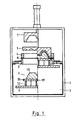
- the molding station essentially consists of a frame 1, a blow box 2, an upper stenter 4, a lower stenter 3 and the height-movable table 5, which carries a deep-drawing mold 6.
- a stretching aid 7 can to be available.
- a horizontally serves to heat the clamped plate 8 Slidable heater 9, which can also be arranged on the side of the molding station, if the Forming station, a separate heating station and a corresponding transport device are upstream.
- the deep-drawing mold 6 is composed of the actual mold 10 and one Mold base plate 11 together. When installed, this mold base plate sits 11 on four spacer strips 12. These spacer strips 12 can be changed in their position arranged either directly on the table 5 or on a carrier plate 14. One all around extending seal 26 can be provided if necessary and seals the vacuum when Deep drawing.
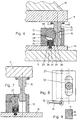
- FIGs 2 to 5 is a simple design as a clamping device trained spacer bar 12 shown.
- In the spacer bars 12 is one Diameter of the bolt 15 corresponding hole provided that is round or as Elongated hole 17 can be formed.
- a slot offers more freedom in terms of Tolerance of the hole spacing when setting the spacer bars 12 to each other when on another format is converted and can extend the mold base 11, due to thermal expansion.
- a slot 18 one sits horizontally Slidable slide 19, which is designed as shown in Figures 3 to 5. He has a fork shape with two webs 21 which engage in the groove 16 of the bolt 15.
- a rejected mold base plate 11 can also be gripped by a bevel 20 be pulled down flat.
- the slide 19 is displaced horizontally either by hand, for which purpose it has a web 22 for gripping or by on the web 22 attacking pneumatic, hydraulic or motor drives that are not closer are shown.
- the four spacer bars 12 either sit on a carrier plate 14 with groove 23 and T-nuts 24, so that the fastening of the spacer strips 12 with an angle 25 the carrier plate 14 can take place. Or the grooves 23 sit directly in the table 5. Die Arrangement on a carrier plate 14 has the advantage that the entire unit carrier plate 14 - spacer bars 12 can be moved out of the molding station for changing a deep-drawing mold 6, e.g. B. by forklift.
- FIGS. 6 to 8 show a locking device, the different Offers improvements.
- the spacer bolts 15 with their groove 16 are in this Execution of a pinch roller 27 gripped by a milled 28 a nose 29 which can be brought into engagement with the surface 30 of the groove 16.
- the Pinch roller 27 is rotatably mounted in the spacer bar 12 and on one side with a Lever 31 connected.
- an elongated hole 32 is provided, in which the Bolt 15 engages.
- the arrangement position of the lever 31 is preferably chosen so that this is up when the lock is open.
- the four standing up Levers 31 thus form a visual aid for the correct insertion of a new deep-drawing mold 6.
- the clamping roller 27 is operatively connected to a clamping device 33 in such a way that when the bolt 15 is unlocked, the clamping roller 27 also removes the clamping between the spacer bar 12 and the carrier plate 14 (see FIG. 7). This is done in that the circumference of the pinch roller 27 presses on a bolt 34 which is pressed upwards with springs 35. The bolt 34 is seated in a sliding block 36, this in a groove 37 in the carrier plate 14. When the mold 10 is locked , the clamping roller 27 stands as shown in FIG. 6 and the cutout 28 causes the springs 35 to clamp between the spacer bar 12 and the carrier plate 14 effect.
- the rotational movement of the pinch roller 27 is limited by a pin 38 which in the Spacer 12 sits and engages in a groove 39 in the pinch roller 27. In this way the two limit positions of the lever 31 are defined.
- each mutually adjustable spacer bars 12 sit on one of the axes of symmetry 40, 41 and the elongated holes 17, 32 in the two mutually adjustable spacer strips 12 run in the direction of their axis of symmetry 40, 41. This changes the length in possible in both directions.
Landscapes
- Engineering & Computer Science (AREA)
- Mechanical Engineering (AREA)
- Moulds For Moulding Plastics Or The Like (AREA)
- Blow-Moulding Or Thermoforming Of Plastics Or The Like (AREA)
- Mounting, Exchange, And Manufacturing Of Dies (AREA)
Description
Distanzleisten zum Überbrücken eines Abstandes zwischen Formträgerplatte und Formhälfte sind dieser Schrift nicht zu entnehmen, da hier eine direkte Verbindung beider Teile erfolgt. Probleme mit der Abstützung gegen Durchbiegung liegen hier nicht vor. Die Lage der Bohrungen in den Formträgerplatten ist festgelegt, sodass nur eine eingeschränkte Größenvarianz an Formhälften aufgenommen werden kann. Bei Tiefziehmaschinen, bei denen eine Platte als Ausgangsmaterial verwendet wird, deren Spannrand als Abfall verbleibt, ist eine enge Anpassung der Tiefziehform und der Spannrahmen an die Abmessungen des Formteils erforderlich, um den Abfall zu minimieren. Auch diese Probleme bestehen bei Spritzgussmaschinen nicht, da dort der Abfall von anderen Faktoren bestimmt wird und die Außenform nebensächlich ist, denn die Innenform ist entscheidend für die Gestalt des hergestellten Teils. Der Fachmann erhält also aus dieser Veröffentlichung keine Anregungen zur Gestaltung einer Formstation einer Vorrichtung zum Tiefziehen einer Folienbahn gemäß Hauptanspruch.
Der Gegenstand der Erfindung wird nachfolgend anhand der schematischen Zeichnungen beschrieben. Es zeigen:
- Figur 1 -
- ein Schnitt durch die Formstation
- Figur 2 -
- einen vergrößerten Querschnitt durch den Bereich Tiefziehform - Tisch gemäß einer ersten Ausführungsform
- Figuren 3 - 5
- Ansichten der Teile gemäß Ausführungsform Fig. 1
- Figuren 6 - 7
- einen vergrößerten Querschnitt durch den Bereich Tiefziehform - Tisch gemäß einer Weiterbildung der Erfindung in zwei Stellungen.
- Figur 8
- eine Draufsicht auf die Ausführung gemäß den Figuren 6 und 7
- Figur 9
- eine Draufsicht auf ein Verriegelungselement in Form einer Lasche
- Figur 10
- eine Draufsicht auf die Trägerplatte mit 4 Distanzleisten
Claims (12)
- Formstation einer Vorrichtung zum Tiefziehen einer erwärmten Platte aus thermoplastischem Kunststoff mittels Differenzdruck;a) mit zwei Spannrahmen (3,4) zum Einspannen der Platte (8);b) einem höhenbeweglichen Tisch (5) zur Aufnahme einer Tiefziehform (6);c) Distanzleisten (12) zwischen dem Tisch (5) oder einer auf dem Tisch (5) angeordneten Trägerplatte (14) und der Formengrundplatte (11) der Tiefziehform (6);d) die zur Anpassung an verschiedene Größen von Tiefziehformen (6) verschiebbar auf dem Tisch (5) oder auf der Trägerplatte (14) gestaltete) und als Verriegelungseinheit für an der Formengrundplatte (11) befestigte Verriegelungselemente (15, 13) ausgebildet sind.
- Formstation nach Anspruch 1 dadurch gekennzeichnet, daß die Verriegelungselemente als Bolzen (15) oder Lasche (13) ausgebildet sind und eine Nut (16) aufweisen, in die ein Gegenstück (19, 27) durch Verschiebung oder Verdrehung in Eingriff gebracht werden kann.
- Formstation nach Anspruch 1 oder 2 dadurch gekennzeichnet, daß das Gegenstück als Schieber (19) ausgebildet ist, der manuell, pneumatisch, hydraulisch oder motorisch verschiebbar ausgebildet ist.
- Formstation nach Anspruch 3 dadurch gekennzeichnet, daß der Schieber (19) zwei Stege (21) mit Schräge (20) aufweist.
- Formstation nach Anspruch 1 oder 2 dadurch gekennzeichnet, daß das Gegenstück als Klemmwalze (27) ausgebildet ist, die durch eine Ausfräsung (28) eine Nase (29) aufweist, die im Eingriff mit der Fläche (30) der Nut (16) steht.
- Formstation nach Anspruch 5 dadurch gekennzeichnet, daß die Klemmwalze (27) mit einem Hebel (31) verbunden ist.
- Formstation nach Anspruch 5 dadurch gekennzeichnet, daß die Klemmwalze (27) mit einem hydraulischen, pneumatischen oder elektrischen Antrieb verbunden ist.
- Formstation nach einem der Ansprüche 5 - 7 dadurch gekennzeichnet, daß die Klemmwalze (27) eine Nut (39) aufweist, in die ein an der Distanzleiste (12) befestigter Stift (38) eingreift und als Verdrehanschlag dient.
- Formstation nach einem der Ansprüche 5 bis 8 dadurch gekennzeichnet, daß die Klemmwalze (27) mit der Klemmeinrichtung (33) für die Klemmung zwischen Distanzleisten (12) und Trägerplatte (14) bzw. Tisch (5) in Wirkverbindung steht.
- Formstation nach Anspruch 9 dadurch gekennzeichnet, daß die Klemmwalze (27) mit ihrem Umfang in Öffnungsstellung auf einem Bolzen (34) anliegt, der in einem Nutenstein (36) sitzt und über Federn (35) betätigt wird, wobei der Nutenstein (36) in einer Nut (37) in der Trägerplatte (14) bzw. im Tisch (5) sitzt, während in der Klemmstellung die Ausfräsung (28) dem Bolzen (34) gegenübersteht.
- Formstation nach Anspruch 6 dadurch gekennzeichnet, daß der Hebel (31) so an der Klemmwalze (27) befestigt ist, daß er in entriegelter Stelllung der Verriegelungseinheit nach oben steht und als Einlegehilfe dient.
- Formstation nach einem der Ansprüche 1 bis 11 dadurch gekennzeichnet, daß in den Distanzleisten (12) je ein Durchbruch in Form eines Langloches (17, 32) vorgesehen ist, wobei die Langlöcher (17, 32) in Richtung der Symmetrieachse (40, 41) der zueinander verstellbaren Distanzleisten (12) verlaufen.
Applications Claiming Priority (2)
| Application Number | Priority Date | Filing Date | Title |
|---|---|---|---|
| DE19840940A DE19840940C1 (de) | 1998-09-08 | 1998-09-08 | Formstation einer Vorrichtung zum Tiefziehen einer erwärmten Platte aus thermoplastischem Kunststoff |
| DE19840940 | 1998-09-08 |
Publications (3)
| Publication Number | Publication Date |
|---|---|
| EP0985514A2 EP0985514A2 (de) | 2000-03-15 |
| EP0985514A3 EP0985514A3 (de) | 2000-03-22 |
| EP0985514B1 true EP0985514B1 (de) | 2002-05-15 |
Family
ID=7880193
Family Applications (1)
| Application Number | Title | Priority Date | Filing Date |
|---|---|---|---|
| EP99116642A Expired - Lifetime EP0985514B1 (de) | 1998-09-08 | 1999-08-26 | Verriegelungseinrichtung zum Verriegeln bzw. Befestigen von unterschiedlich grossen Formwerkzeugen auf der Warmvormmaschine |
Country Status (3)
| Country | Link |
|---|---|
| EP (1) | EP0985514B1 (de) |
| AT (1) | ATE217571T1 (de) |
| DE (2) | DE19840940C1 (de) |
Families Citing this family (3)
| Publication number | Priority date | Publication date | Assignee | Title |
|---|---|---|---|---|
| CN110193923B (zh) * | 2019-06-11 | 2024-06-07 | 汕头市凹凸包装机械有限公司 | 热成型机的锁模装置 |
| CN110861808A (zh) * | 2019-11-29 | 2020-03-06 | 上海龙腾科技股份有限公司 | 泡罩机预热板加热结构 |
| DE102020124641A1 (de) | 2020-09-22 | 2022-03-24 | Illig Maschinenbau Gmbh & Co. Kg | Arbeitsstation einer Thermoformmaschine |
Family Cites Families (5)
| Publication number | Priority date | Publication date | Assignee | Title |
|---|---|---|---|---|
| DE3313020C1 (de) * | 1983-04-12 | 1984-07-19 | Adolf Illig Maschinenbau Gmbh & Co, 7100 Heilbronn | Unterbau zum Überbrücken des Abstandes zwischen einem Formtisch einer Tiefziehmaschine und einer Tiefziehform |
| US5096405A (en) * | 1990-09-18 | 1992-03-17 | American Aerostar Corporation | Powered mounts for quickly mounting mold parts on molding machine platens |
| DE9100937U1 (de) * | 1991-01-15 | 1991-05-16 | Brandt, Angelika, 7768 Stockach | Handbetätigbare Schnellspannvorrichtung für Spritzgießwerkzeuge |
| AT396443B (de) * | 1991-04-25 | 1993-09-27 | Engel Gmbh Maschbau | Formaufspannplatte und werkzeugwechselwagen für eine spritzgiessmaschine |
| DE19721593C2 (de) * | 1997-05-23 | 2001-06-28 | Illig Maschinenbau Adolf | Formstation einer Vorrichtung zum Tiefziehen einer erwärmten Platte aus thermoplastischem Kunststoff |
-
1998
- 1998-09-08 DE DE19840940A patent/DE19840940C1/de not_active Expired - Fee Related
-
1999
- 1999-08-26 AT AT99116642T patent/ATE217571T1/de not_active IP Right Cessation
- 1999-08-26 DE DE59901437T patent/DE59901437D1/de not_active Expired - Lifetime
- 1999-08-26 EP EP99116642A patent/EP0985514B1/de not_active Expired - Lifetime
Also Published As
| Publication number | Publication date |
|---|---|
| DE19840940C1 (de) | 2000-03-30 |
| ATE217571T1 (de) | 2002-06-15 |
| EP0985514A2 (de) | 2000-03-15 |
| DE59901437D1 (de) | 2002-06-20 |
| EP0985514A3 (de) | 2000-03-22 |
Similar Documents
| Publication | Publication Date | Title |
|---|---|---|
| DE69309185T2 (de) | Presse zum Formen eines Gegenstandes aus Verbundmaterial mit verstärkenden Fasern in einer Polimermatrix | |
| DE69219879T2 (de) | Formträgerplattestruktur | |
| DE4314641C2 (de) | Spannrahmen für Tiefziehmaschinen | |
| EP0676477B1 (de) | Vorrichtung und Verfahren zum Einschlagen oder Buggen | |
| EP1127676B1 (de) | Vorrichtung zum Verformen von thermoplastischen Materialien | |
| EP0557614A1 (de) | Verfahren zum Verschweissen von halogenfreien Thermoplastfolien | |
| EP0985514B1 (de) | Verriegelungseinrichtung zum Verriegeln bzw. Befestigen von unterschiedlich grossen Formwerkzeugen auf der Warmvormmaschine | |
| DE10235151B4 (de) | Haltevorrichtung für eine Extrusionsdüse | |
| DE3620954C2 (de) | ||
| EP0249059B1 (de) | Druckluftantrieb für Stanz-, Schneid- und Prägeeinrichtungen | |
| DE19629196C2 (de) | Thermoformvorrichtung | |
| DE2542015C3 (de) | Verriegelungseinrichtung an einer Blasformeinheit für eine Kunststoffblasmaschine | |
| DE19723561A1 (de) | Verstellbarer Spannrahmen für die Formstation einer Thermoformmaschine | |
| DE19814615C1 (de) | Verstellbarer oberer Spannrahmen für die Formstation einer Thermoformmaschine | |
| DE4432163A1 (de) | Vorrichtung zum Herstellen von Spritzguss-Formteilen | |
| EP1848577B1 (de) | Spritzgiessmaschine zur verarbeitung von kunststoffen | |
| EP0868993B1 (de) | Kühlvorrichtung im oder am Spannrahmen für Warmumformungsmaschinen | |
| DE19536867C1 (de) | Verkleinerungsrahmen für Thermoformmaschine | |
| EP1858682A1 (de) | ANORDNUNG ZUR AUFNAHME EINER GIEßFORM | |
| EP3672778B1 (de) | Vorform-vorrichtung zum positionieren von extrudierten kautschukmischungen und ein die vorform-vorrichtung aufweisendes extruder-form-system zum ausformen von extrudierten kautschukmischungen zu einem gesamtkautschukelement sowie eine entsprechende extruderanlage | |
| DE202007003330U1 (de) | Formwerkzeug | |
| DE4122567A1 (de) | Formwerkstueck-klemmvorrichtung mit klemmechanismus und bestaetigungsmechanismus | |
| DE102004025630B4 (de) | Werkzeug zum Spritzgießen von Formkörpern aus Kunststoff | |
| DE2344866A1 (de) | Verfahren und vorrichtung zum herstellen von formlingen durch thermoformen | |
| DE112013006092T5 (de) | Anlage und Verfahren zur Herstellung eines Werkstücks aus Thermoplast |
Legal Events
| Date | Code | Title | Description |
|---|---|---|---|
| PUAI | Public reference made under article 153(3) epc to a published international application that has entered the european phase |
Free format text: ORIGINAL CODE: 0009012 |
|
| PUAL | Search report despatched |
Free format text: ORIGINAL CODE: 0009013 |
|
| AK | Designated contracting states |
Kind code of ref document: A2 Designated state(s): AT BE CH CY DE DK ES FI FR GB GR IE IT LI LU MC NL PT SE |
|
| AX | Request for extension of the european patent |
Free format text: AL;LT;LV;MK;RO;SI |
|
| AK | Designated contracting states |
Kind code of ref document: A3 Designated state(s): AT BE CH CY DE DK ES FI FR GB GR IE IT LI LU MC NL PT SE |
|
| AX | Request for extension of the european patent |
Free format text: AL;LT;LV;MK;RO;SI |
|
| 17P | Request for examination filed |
Effective date: 20000215 |
|
| AKX | Designation fees paid |
Free format text: AT BE CH CY DE DK ES FI FR GB GR IE IT LI LU MC NL PT SE |
|
| 17Q | First examination report despatched |
Effective date: 20010222 |
|
| GRAG | Despatch of communication of intention to grant |
Free format text: ORIGINAL CODE: EPIDOS AGRA |
|
| GRAG | Despatch of communication of intention to grant |
Free format text: ORIGINAL CODE: EPIDOS AGRA |
|
| GRAH | Despatch of communication of intention to grant a patent |
Free format text: ORIGINAL CODE: EPIDOS IGRA |
|
| GRAH | Despatch of communication of intention to grant a patent |
Free format text: ORIGINAL CODE: EPIDOS IGRA |
|
| GRAA | (expected) grant |
Free format text: ORIGINAL CODE: 0009210 |
|
| AK | Designated contracting states |
Kind code of ref document: B1 Designated state(s): AT BE CH CY DE DK ES FI FR GB GR IE IT LI LU MC NL PT SE |
|
| PG25 | Lapsed in a contracting state [announced via postgrant information from national office to epo] |
Ref country code: NL Free format text: LAPSE BECAUSE OF FAILURE TO SUBMIT A TRANSLATION OF THE DESCRIPTION OR TO PAY THE FEE WITHIN THE PRESCRIBED TIME-LIMIT Effective date: 20020515 Ref country code: IE Free format text: LAPSE BECAUSE OF FAILURE TO SUBMIT A TRANSLATION OF THE DESCRIPTION OR TO PAY THE FEE WITHIN THE PRESCRIBED TIME-LIMIT Effective date: 20020515 Ref country code: FR Free format text: LAPSE BECAUSE OF FAILURE TO SUBMIT A TRANSLATION OF THE DESCRIPTION OR TO PAY THE FEE WITHIN THE PRESCRIBED TIME-LIMIT Effective date: 20020515 Ref country code: FI Free format text: LAPSE BECAUSE OF FAILURE TO SUBMIT A TRANSLATION OF THE DESCRIPTION OR TO PAY THE FEE WITHIN THE PRESCRIBED TIME-LIMIT Effective date: 20020515 |
|
| REF | Corresponds to: |
Ref document number: 217571 Country of ref document: AT Date of ref document: 20020615 Kind code of ref document: T |
|
| REG | Reference to a national code |
Ref country code: GB Ref legal event code: FG4D Free format text: NOT ENGLISH Ref country code: CH Ref legal event code: EP |
|
| REG | Reference to a national code |
Ref country code: IE Ref legal event code: FG4D Free format text: GERMAN |
|
| REF | Corresponds to: |
Ref document number: 59901437 Country of ref document: DE Date of ref document: 20020620 |
|
| RAP2 | Party data changed (patent owner data changed or rights of a patent transferred) |
Owner name: ADOLF ILLIG MASCHINENBAU GMBH & CO. KG |
|
| PG25 | Lapsed in a contracting state [announced via postgrant information from national office to epo] |
Ref country code: SE Free format text: LAPSE BECAUSE OF FAILURE TO SUBMIT A TRANSLATION OF THE DESCRIPTION OR TO PAY THE FEE WITHIN THE PRESCRIBED TIME-LIMIT Effective date: 20020815 Ref country code: DK Free format text: LAPSE BECAUSE OF FAILURE TO SUBMIT A TRANSLATION OF THE DESCRIPTION OR TO PAY THE FEE WITHIN THE PRESCRIBED TIME-LIMIT Effective date: 20020815 |
|
| PG25 | Lapsed in a contracting state [announced via postgrant information from national office to epo] |
Ref country code: PT Free format text: LAPSE BECAUSE OF FAILURE TO SUBMIT A TRANSLATION OF THE DESCRIPTION OR TO PAY THE FEE WITHIN THE PRESCRIBED TIME-LIMIT Effective date: 20020816 Ref country code: GR Free format text: LAPSE BECAUSE OF FAILURE TO SUBMIT A TRANSLATION OF THE DESCRIPTION OR TO PAY THE FEE WITHIN THE PRESCRIBED TIME-LIMIT Effective date: 20020816 |
|
| PG25 | Lapsed in a contracting state [announced via postgrant information from national office to epo] |
Ref country code: LU Free format text: LAPSE BECAUSE OF NON-PAYMENT OF DUE FEES Effective date: 20020826 Ref country code: AT Free format text: LAPSE BECAUSE OF NON-PAYMENT OF DUE FEES Effective date: 20020826 |
|
| PG25 | Lapsed in a contracting state [announced via postgrant information from national office to epo] |
Ref country code: CY Free format text: LAPSE BECAUSE OF FAILURE TO SUBMIT A TRANSLATION OF THE DESCRIPTION OR TO PAY THE FEE WITHIN THE PRESCRIBED TIME-LIMIT Effective date: 20020831 Ref country code: BE Free format text: LAPSE BECAUSE OF NON-PAYMENT OF DUE FEES Effective date: 20020831 |
|
| NLT2 | Nl: modifications (of names), taken from the european patent patent bulletin |
Owner name: ADOLF ILLIG MASCHINENBAU GMBH & CO. KG |
|
| GBT | Gb: translation of ep patent filed (gb section 77(6)(a)/1977) |
Effective date: 20020812 |
|
| NLV1 | Nl: lapsed or annulled due to failure to fulfill the requirements of art. 29p and 29m of the patents act | ||
| PG25 | Lapsed in a contracting state [announced via postgrant information from national office to epo] |
Ref country code: ES Free format text: LAPSE BECAUSE OF FAILURE TO SUBMIT A TRANSLATION OF THE DESCRIPTION OR TO PAY THE FEE WITHIN THE PRESCRIBED TIME-LIMIT Effective date: 20021128 |
|
| REG | Reference to a national code |
Ref country code: IE Ref legal event code: FD4D Ref document number: 0985514E Country of ref document: IE |
|
| EN | Fr: translation not filed | ||
| BERE | Be: lapsed |
Owner name: ADOLF *ILLIG MASCHINENBAU G.M.B.H. & CO. Effective date: 20020831 |
|
| PG25 | Lapsed in a contracting state [announced via postgrant information from national office to epo] |
Ref country code: MC Free format text: LAPSE BECAUSE OF NON-PAYMENT OF DUE FEES Effective date: 20030301 |
|
| PLBE | No opposition filed within time limit |
Free format text: ORIGINAL CODE: 0009261 |
|
| STAA | Information on the status of an ep patent application or granted ep patent |
Free format text: STATUS: NO OPPOSITION FILED WITHIN TIME LIMIT |
|
| 26N | No opposition filed |
Effective date: 20030218 |
|
| PG25 | Lapsed in a contracting state [announced via postgrant information from national office to epo] |
Ref country code: LI Free format text: LAPSE BECAUSE OF NON-PAYMENT OF DUE FEES Effective date: 20030831 Ref country code: CH Free format text: LAPSE BECAUSE OF NON-PAYMENT OF DUE FEES Effective date: 20030831 |
|
| REG | Reference to a national code |
Ref country code: CH Ref legal event code: PL |
|
| PGFP | Annual fee paid to national office [announced via postgrant information from national office to epo] |
Ref country code: DE Payment date: 20180817 Year of fee payment: 20 Ref country code: IT Payment date: 20180823 Year of fee payment: 20 |
|
| PGFP | Annual fee paid to national office [announced via postgrant information from national office to epo] |
Ref country code: GB Payment date: 20180828 Year of fee payment: 20 |
|
| REG | Reference to a national code |
Ref country code: DE Ref legal event code: R071 Ref document number: 59901437 Country of ref document: DE |
|
| REG | Reference to a national code |
Ref country code: GB Ref legal event code: PE20 Expiry date: 20190825 |
|
| PG25 | Lapsed in a contracting state [announced via postgrant information from national office to epo] |
Ref country code: GB Free format text: LAPSE BECAUSE OF EXPIRATION OF PROTECTION Effective date: 20190825 |