EP0985563A2 - Dispositif élévateur - Google Patents
Dispositif élévateur Download PDFInfo
- Publication number
- EP0985563A2 EP0985563A2 EP99122575A EP99122575A EP0985563A2 EP 0985563 A2 EP0985563 A2 EP 0985563A2 EP 99122575 A EP99122575 A EP 99122575A EP 99122575 A EP99122575 A EP 99122575A EP 0985563 A2 EP0985563 A2 EP 0985563A2
- Authority
- EP
- European Patent Office
- Prior art keywords
- threaded rod
- inner tube
- lifting device
- handle
- bolt
- Prior art date
- Legal status (The legal status is an assumption and is not a legal conclusion. Google has not performed a legal analysis and makes no representation as to the accuracy of the status listed.)
- Granted
Links
Images







Classifications
-
- B—PERFORMING OPERATIONS; TRANSPORTING
- B60—VEHICLES IN GENERAL
- B60S—SERVICING, CLEANING, REPAIRING, SUPPORTING, LIFTING, OR MANOEUVRING OF VEHICLES, NOT OTHERWISE PROVIDED FOR
- B60S9/00—Ground-engaging vehicle fittings for supporting, lifting, or manoeuvring the vehicle, wholly or in part, e.g. built-in jacks
- B60S9/14—Ground-engaging vehicle fittings for supporting, lifting, or manoeuvring the vehicle, wholly or in part, e.g. built-in jacks for both lifting and manoeuvring
- B60S9/16—Ground-engaging vehicle fittings for supporting, lifting, or manoeuvring the vehicle, wholly or in part, e.g. built-in jacks for both lifting and manoeuvring for operating only on one end of vehicle
- B60S9/18—Ground-engaging vehicle fittings for supporting, lifting, or manoeuvring the vehicle, wholly or in part, e.g. built-in jacks for both lifting and manoeuvring for operating only on one end of vehicle mechanically
-
- B—PERFORMING OPERATIONS; TRANSPORTING
- B60—VEHICLES IN GENERAL
- B60D—VEHICLE CONNECTIONS
- B60D1/00—Traction couplings; Hitches; Draw-gear; Towing devices
- B60D1/24—Traction couplings; Hitches; Draw-gear; Towing devices characterised by arrangements for particular functions
- B60D1/36—Traction couplings; Hitches; Draw-gear; Towing devices characterised by arrangements for particular functions for facilitating connection, e.g. hitch catchers
-
- B—PERFORMING OPERATIONS; TRANSPORTING
- B60—VEHICLES IN GENERAL
- B60D—VEHICLE CONNECTIONS
- B60D1/00—Traction couplings; Hitches; Draw-gear; Towing devices
- B60D1/58—Auxiliary devices
- B60D1/66—Props
Definitions
- the invention relates to a lifting device, in particular for a support and Carrier device or the like for the drawbar of vehicle trailers.
- the invention provides a holding device with which it is possible is the drawbar of a vehicle trailer with little effort and time to the desired position (altitude) for coupling or uncoupling to bring a towing vehicle.
- the drawbar of vehicle trailers is provided according to the invention to be equipped with a holding or lifting device which has a base, a support wheel or the like. and has a height adjustment device and the has a quick coarse height adjustment and a fine height adjustment.
- a pedestal which consists of an elongated metal profile exists that is articulated on one end of the drawbar that the The axis of rotation is at right angles to the drawbar and at the other end of the A stand is attached to a stand
- the height adjustment device consists of tubes that can be pushed into one another, the outermost of which Tube is rotatably attached to the drawbar and a first inner tube slidably accommodates on the outside e.g. Has notches in the at least one pawl, which is articulated to the outer tube, snaps into place is, a further inner tube or an inner rod in the first inner tube is arranged on one side with the base, adjacent to the unwinding device, is connected and the like via a thread. slidable in the inner tube and is definable. Instead of the pawls can also be moved Locking bolts or devices with the same mode of operation are used become.
- the configuration according to the invention makes it possible to follow the path that is necessary to bring the base into contact with the ground or Conversely, to cope very quickly, because the height adjustment is not above that Turn a handle to move the two inner tubes against each other must be done, but only by manually releasing the pawls from the locking position so that the inner tubes by moving in outer tube very quickly bring the base into contact with the ground.
- the rest of the lifting work is done conventionally with the handle, since it is larger here Forces must be applied.
- the handle for conventional height adjustment is a preferred one Embodiment designed as a hand crank, which advantageously has a crank lock so that vibrations during occur while driving, the hand crank does not move.
- teeth on the outer circumference of the first inner tube towards the hand crank to form a grid ring.
- a locking pin engages for locking, the part of the hand crank is in the grid ring.
- the hand crank can be used according to two preferred embodiments.
- the hand crank has a rotary knob that operates the crank against the Force is pressed down by a spring arranged in its interior, wherein a rocker inside the hand crank the locking bolt from the grid ring pulls out.
- the hand crank itself is a seesaw formed, which is pressed down against a spring force, the end specified locking bolt is guided out of the grid.
- the pivot point of the rocker is at the point at which the hand crank touches the threaded rod is articulated.
- this or a Hand crank designed such that the hand crank for fine height adjustment no longer has to describe a full circle, but that partial circles are sufficient, which is particularly advantageous in tight spaces is.
- the grid is fixed to the threaded rod while the hand crank is connected to the threaded rod as a pivot via a freewheel is. If the locking bolt is in engagement with the raster ring, so can be moved by turning the hand crank the raster ring and it there is a height adjustment. The grid is over a plain bearing set against the first inner tube. By pressing the hand crank the connection to the grid ring is released.
- the height can be adjusted by "moving back and forth”.
- the outermost tube which can also be moved into one another Pipes existing lifting device attached to the drawbar or articulated is.
- an inner tube is stored, which from the outermost tube protrudes on the side opposite the drawbar and a support wheel or the like. wearing.
- There is a threaded rod in the inner tube the side of the two pipes made of these on the drawbar protrudes, being opposite the outermost tube via a plain bearing in its position is fixed.
- the handle is attached to the protruding part of the threaded rod.
- the inner tube is opposite the threaded rod by means of a threaded body supported by through openings in the inner tube in the Thread of the threaded rod engages.
- the threaded body is according to one embodiment at least divided into two, preferably it consists of four segments. The part of these segments that protrudes from the inner tube is can be pushed in against a spring force via a pressure ring, whereby both threads interlock. Is the pressure ring, which is preferably operated by rotation will, in the position in which it does not attach the segments to the threaded rod presses, the inner tube, which is now independent can be moved by the threaded rod, pulled out so far, that the jockey wheel or the like. touches the ground Brought segments of the threaded body back into engagement with the threaded rod, so that the height adjustment can now be carried out by means of the handle can.
- the actuation is preferably carried out via a handle vertical slot in the outer tube attacks directly on the pressure ring.
- the thread of the threaded rod and / or the Segments of the threaded body are square or taper inwards be formed with regard to the flank shape of the threads. Thereby the segments are pressed against the threaded rod under load, so that an automatic securing of the threaded body against unintentional release the threaded rod.
- the embodiment with the threaded body divided into segments can also be achieved by a device with a two-part nut that holds the threaded rod embraced on all sides, to be replaced.
- the two parts of the mother are in one Housing slidably mounted and are spring-loaded against the Threaded rod pressed so that a fine height adjustment with the handle can be made.
- the mother parts are used for coarse height adjustment against the spring force by means of appropriate handling of the threaded parts pulled away so that the housing with the split nut or the drawbar can be adjusted independently of the handle of the threaded rod.
- Threaded rod is surrounded on one side by a nut body through a Opening is made in the inner tube and against the spring force of the threaded rod can be separated so that there is free movement.
- the threaded rod can also from another nut body on the free half side are encompassed, then using a corresponding device, e.g. a universal joint when separating the first nut body from the threaded rod the second half-sided nut body also by means of a handle is withdrawn from the threaded rod.
- Such a universal joint or the like. is with one in all embodiments two-part or multi-part nut or thread body can be used.
- the one Support wheel can have a device for automatic positioning and fixation of the support wheel while driving, so that e.g. advantageously the jockey wheel about a vertical axis while driving rotates.
- a device for automatic positioning and fixation of the support wheel while driving so that e.g. advantageously the jockey wheel about a vertical axis while driving rotates.
- it is provided on the second inner tube adjacent to the support wheel to attach a small wheel, the axis of rotation of which is at right angles to the second inner tube stands.
- This wheel is positioned in such a way that the wheel points in the direction in which the support wheel is to be fixed.
- the lower edge of the first inner tube is chamfered. If the jockey wheel is now pulled up, the small wheel runs on the slanted one Edge to the highest point of the slope. In this position the support wheel is automatically rotated and fixed.
- the lifting device 100 shown in FIGS. 1 and 2 is on a drawbar 10 of a vehicle trailer, not shown, and includes a Height adjustment device 11 and a pedestal 12.
- the drawbar 10 instructs the side 13 facing the vehicle has a cross member 14 on which a Coupling, not shown, can be attached to the vehicle.
- On the cross member 14 the base 12 is articulated at one end 15.
- On the opposite A rolling plate 17 is provided at the end 16 of the base 12.
- the Height adjustment device 11 consists of an outer tube 18 which on the Drawbar 10 is articulated at point A.
- In the outer tube 18 is a first inner one Tube 19 slidably mounted, this only from the outer tube 18 a small part is included.
- the notches 21, 22 are not at the same height, based on the longitudinal axis L of the first inner one Tube 19, but arranged against each other, so that always only a pawl 23 engages in the respective notch 21 while the other Pawl 24 rests on the outside 20.
- first inner tube 19 is a introduced further inner tube (innermost inner tube) 31, which on the Stand 12 facing end 32 protrudes from the first inner tube 19 and is articulated on the stand 12 adjacent to the rolling plate 17 at 32a.
- the first inner tube 19 and the further inner tube 31 are by means of a Handle 33 slidable against each other.
- the handle 33 consists of a Hand crank 34 and a threaded rod 35, which in a corresponding Thread 36 of the further inner tube 31 engages, wherein it by means of a Plain bearing 37, which is fixed on the threaded rod 35, with respect to the first inner tube 19 is supported.
- the pawls 23, 24 are each with a handle-like handle 38, 39 with which a release of the pawl 23, 24 from the engagement in the notch 21, 22 is performed. This is necessary if the export length is to be shortened, while the exit without Operation of the handle is possible because of the shape and the Dodge the pawls 23, 24 against the spring force.
- the pawls 23, 24 are designed as locking bolts 40, 41, which in one Guided housing 42 and by compression springs supported against the housing 42 27, 28 held in their locking position blocking the movement of the tube 19 become.
- the pivoted lever-like handle articulated on the tube 19 at 43 44 acts upon the stop rings one after the other during a pivoting movement 45, 46, the stop ring 45 being arranged on the locking bolt 41 is.
- Arranged locking bolts 40, 41 achieve fine locking.
- the the Notches 21 forming the grid profile can be spaced apart from one another to be ordered. The advantage is greater stability.
- a notch formed as a recessed groove is provided for transportation.
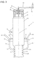
- FIG. 5 consists of an outer tube 210, which is fixed with a drawbar, not shown, at a suitable angle connected is.
- An inner tube 211 is slidable in the outer tube 210 stored, that at the end facing away from the drawbar end 212 of the outer tube 210 protrudes.
- On the protruding part 213 of the inner tube 211 a support wheel 214 is attached.
- Inside the inner tube 211 is a threaded rod 215 stored, the opposite of the support wheel 214 End 216 of the inner tube 211 and the outer tube protrudes.
- the threaded rod 215 by means of a slide bearing 217 axially fixed or rotatably mounted.
- the threaded rod 215 has no thread to this area 218 is followed by a handle in the form of a hand crank 219.
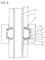
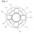
- the inner tube 211 is opposite threaded rod 215 by means of a threaded body 220 supported (Fig. 6 and 7).
- openings 221 are made in the inner tube 211, through the segments 222 of the threaded body 220 to the threaded rod 215 are listed.
- the outwardly projecting part of the segments is managed by one encircling pressure ring 223, wherein the segments 222 a horizontal have extending groove 224, which with a corresponding tongue 225 corresponds to the inner wall 226 of the pressure ring 223.
- the pressure ring 223 comprises segments 222 from three sides.
- the segments 222 are created using a compression spring 227 located on the inner tube 211 and the respective Segment 222 is supported, pushed away from the thread 228 of the threaded rod 215, so that the thread 228 of the threaded rod 215 and the thread 229th the threaded body 220 does not come into contact. So that the pressure ring 223 can be operated, is in the outer tube 210 a vertically extending Slot 223a is provided, through which a handle 223b is guided by means of the the pressure ring 223 is actuated.
- the contact is made by rotating the pressure ring 223.
- the respective segment 222 which is in a corresponding recess 230 rests on the inner wall 226 of the pressure ring, by acting on the Segments 222 with pressure through a slope 231, which from the recess 230 in Direction of the inner tube 211 leads to the threaded rod 215 in contact brought.
- FIG. 8 shows a device for connecting the threaded rod 215 to the inner tube, which instead of the embodiment with the threaded body 220 and the pressure ring 223 is used.
- a two-part nut body 232 which holds the threaded rod 215 encompasses on all sides.
- the two parts 233, 234 of the nut body 232 are rectangular when folded and are in one Housing 235 mounted horizontally displaceable, the housing 235 in right angle to the threaded rod 215 on the inner tube 211 is fixed.
- the two parts 233, 234 are each by means of a compression spring 236, which is supported on the housing 235 and a part 233 or 234, to the threaded rod 215 pressed and brought into contact with it.
- Parts 233, 234 of the Nut body 232 are with a pull axis 237 on that of the threaded rod 215 facing away are attached, provided. These pull axes 237 are led out of the housing 235 and are there with a handle 238 provided.
- FIGS. 9 and 10 show another device for connecting the Threaded rod 215 with the inner tube 211.
- the threaded rod 215 has an external thread 239, which is in 90 ° steps is divided in such a way that there are alternating areas without and with external thread 239 there.
- the inner tube 211 For connection to the inner tube 211 are two nuts 240, 241 are provided, one nut 240 being of the same type divided thread 242 has like the threaded rod 215. In a corresponding Position, this nut 240 is freely displaceable on the threaded rod 215.
- the other nut 241 has continuous threads.
- the nut 240 with the divided thread 242 has a retracted Area 243 an external thread 244 on which the other nut 241 can be screwed on by means of a second internal thread 245.
- One of the nuts 240, 241 is fixed to the inner tube 211.
- FIG. 11 shows yet another embodiment of the device for Coarse height adjustment or for connecting the threaded rod 215 to the inner tube 211.
- the threaded rod 215 is a nut body 245 in one Includes range of 180 °.
- This nut body 245 is through a through hole 246 guided in the inner tube 211.
- the through opening 246 is covered by a housing 247 in which i.a. the nut body 245 is stored.
- the nut body 245 points on that facing away from the threaded rod 215 Page a pulling bolt 248 on the opening 249 after is guided on the outside and has a handle 250.
- the nut body 245 is by a coil spring 251, in the middle of the Drawing bolt 248 is located, pressed against the threaded rod 215.
- the spiral spring 251 is on the rear 252 of the nut body 245 and the inner wall 253 of the housing 247 supported.
- the drawing bolt 248 may be hingedly connected to nut body 245, then it has a lateral extension, which is not shown here, in a L-shaped groove in the inner wall 253, or on a Z-profile or the like. walks along, so that a lock is possible by turning the handle 250 is.
- a locking pin 255 in Form a rocker articulated by means of a compression spring 256, which is on the outside 254 and the end 257 of the locking bolt facing the threaded rod 215 255 is supported, pushes in the direction of the handle 250.
- a lateral extension 258 of the locking bolt 255 engages behind a locking ring 259, which is located on the drawing bolt 248. But it can also be provided be that the lateral extension for securing when the nut body is in contact 245 on the threaded rod 215, the handle 250 engages behind.
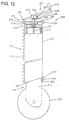
- a lifting device 300 is shown, the drawbar and the outer tube are not shown.
- the inner tube 310 has a grid profile 311 with notches 312 according to the embodiment of FIGS. 3 and 4.
- first inner tube 310 In the first inner tube 310 is another inner tube (innermost Inner tube) 313 slidably mounted.
- the further inner tube 313 protrudes on the one side, i.e. on the bottom side out of the first inner tube 310.
- a support wheel 315 To the protruding part 314 of the further inner tube 313 is a support wheel 315 rotatably attached.
- a threaded rod 316 is screwed into the further inner tube 313, which protrudes on the side opposite the support wheel 315.
- the threaded rod 316 is in a through hole 317 by means of a Slide bearing 318 in the closed side 319 of the first inner tube 310 rotatably mounted.
- the protruding part 320 of the threaded rod 316 is articulated to a crank handle 321 with a knob 322.
- a coupling member 323 is used for connection.
- the hand crank 321 or the part 324 which is articulated on the coupling member 323 is over the Pivot point out and points at the opposite of the knob 322 End a locking bolt 325 fixed at right angles to it points in the direction of the inner tube 310.
- the crank handle 321 is locked in place by spring force Position held.
- the spring 329 is on the coupling member 323 to a spring holder 330 and supported on the part 324 articulated on the coupling member, wherein the knob is pushed away from the inner tube 310.
- FIG. 12 also shows a device 331 for automatic positioning of the support wheel 315.
- This is the lower edge facing the support wheel 315 332 of the first inner tube 310 and the protruding Part 314 of the further inner tube 313 is provided with a small wheel 333.
- the wheel 333 is rotatably mounted on an axis 334, which is on the right Angle protrudes from the further inner tube 313. If the threaded rod 316 the wheel is completely screwed into the further inner tube 313 333 at the point of the bevelled lower edge 332 that the support wheel 315 furthest away.
- FIG. 13 shows an embodiment variant of a hand crank 335 with locking
- the crank handle 335 is fixedly connected to the threaded rod 316.
- the rotary knob 336 of the hand crank 335 has a compression spring 337 inside on.
- the rocker 340 is in the part 339, which is designed as a hollow profile open on one side, arranged and articulated in the middle.
- the opposite end from pin 338 341 of the rocker 340 has a locking bolt 342, which in one at point 343 indicated toothing engages for locking.
- the base 12 is made of an elongated metal profile there is that is articulated on one end of the drawbar 10 that the Axis of rotation of the base 12 is at right angles to the drawbar 10, and that at the other end 15 of the pedestal 12, the stand-up or unrolling device is attached, and that the outer tube 18 is pivotable on the Drawbar 10 is articulated.
- the rolling device from a rounded Roll plate 17 is made, or that the roll device consists of a wheel.
- the wheel has a locking device.
- a variant shows that the pressure ring 223 the segments 222 on three sides includes.
- the housing 235 on the inner tube 211 is set.
- the housing 235 on the part 213 of the inner tube protruding from the outer tube 210 211 is set.
- pull bolt 248 has a handle at its free end 250 has.
- Another embodiment is that the hand crank 321 with is equipped with a locking device.
- the teeth on the first inner Circular surface closing tube 310 is arranged all the way to the handle is.
- the handle has a freewheel is connected to the threaded rod and that the toothing in the form of a The ring gear is firmly connected to the threaded rod, which passes through the center Sprocket is guided.
- a foot Stand element is arranged on inner components.
- Complementary training is also conceivable, where the foot in the area of Outer tube is mounted.
- the outer tube on the vehicle or other supporting part is struck, but that the inner tube protrudes from the arrangement and is struck on the vehicle and that the outer tube is telescopic is positioned.
- an elastic tension member For example, it is possible to position the telescopic element relative to the movable element or relative to the supporting vehicle or to another carrier, braced elastically.
- the elastic tension can be done, for example, with an elastic band, with a linear one Arrangement, spiral springs or comparable elements are also appropriate.
- an elastic band When using an elastic band, a roll-like can be used to protect the material Redirection for the elastic band may be provided. Purpose of this feedback device is, when loosening the quick grid, the feedback in to accelerate the starting position. So there are no additional ones Operator operations required.
- the dimensioning of the feedback device can vary Considerations. In addition to the dimensioning already described, where a return is triggered automatically, it is possible to design the spring forces so that only weight forces are compensated become. If the detent was released, then no automatic Returns are made, but manual returns are minimal To muster forces.
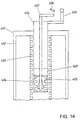
- an outer tube 401 there is an inner tube 402 arranged in the region of the outer tube 401 facing inner expansion is provided with a thread 403.
- a central tube 404 is guided, within which a expandable threaded body 405 is arranged.
- the threaded body 405 can with its thread profile through recesses 406 of the central tube 404 are passed through and engages in the thread 403 of the inner tube 402 a.
- Adjustment element 407 is provided, which can be designed as a rod.
- the Actuator 407 is coupled to a trigger device 408 that either performs a spreading operation of the threaded body 405, or a return of the threaded body 405 in the starting position.
- the spreading process can, for example, by conically shaped elements in the area of Threaded body are caused in a longitudinal direction of the actuator 407 are movable. Also rotatable eccentric Components are used.
- a holding element 409 in above the threaded body 405 the central tube 404 inserted. Through the holding element 409 is the actuator 407 passed.
- FIG. 15 shows a variant of the embodiment according to FIG. 8.
- Eccentric elements 420 are arranged between the components 233, 234, which is a separation of the threaded body or the two Parts of the threaded body from the central thread cause and a relative Allow displacement to each other.
- these eccentric elements 420 is possible without affecting the functionality at 15 to omit the components 236, 237, 238. It the construction work is thus considerably simplified. Basically but it is also conceivable to additionally arrange the eccentric elements 420, as shown in Fig. 15.
Landscapes
- Engineering & Computer Science (AREA)
- Mechanical Engineering (AREA)
- Transportation (AREA)
- Handcart (AREA)
- Grinding Of Cylindrical And Plane Surfaces (AREA)
- Gripping On Spindles (AREA)
- Constituent Portions Of Griding Lathes, Driving, Sensing And Control (AREA)
- Forklifts And Lifting Vehicles (AREA)
Applications Claiming Priority (5)
| Application Number | Priority Date | Filing Date | Title |
|---|---|---|---|
| DE9405344U DE9405344U1 (de) | 1994-03-30 | 1994-03-30 | Haltevorrichtung |
| DE9405344U | 1994-03-30 | ||
| DE19508089 | 1995-03-08 | ||
| DE19508089A DE19508089A1 (de) | 1994-03-30 | 1995-03-08 | Hebevorrichtung |
| EP95104771A EP0688687B1 (fr) | 1994-03-30 | 1995-03-30 | Dispositif élévateur |
Related Parent Applications (1)
| Application Number | Title | Priority Date | Filing Date |
|---|---|---|---|
| EP95104771.1 Division | 1995-03-30 |
Publications (3)
| Publication Number | Publication Date |
|---|---|
| EP0985563A2 true EP0985563A2 (fr) | 2000-03-15 |
| EP0985563A3 EP0985563A3 (fr) | 2000-05-17 |
| EP0985563B1 EP0985563B1 (fr) | 2004-09-22 |
Family
ID=6906702
Family Applications (1)
| Application Number | Title | Priority Date | Filing Date |
|---|---|---|---|
| EP99122575A Expired - Lifetime EP0985563B1 (fr) | 1994-03-30 | 1995-03-30 | Dispositif élévateur |
Country Status (2)
| Country | Link |
|---|---|
| EP (1) | EP0985563B1 (fr) |
| DE (4) | DE9405344U1 (fr) |
Cited By (1)
| Publication number | Priority date | Publication date | Assignee | Title |
|---|---|---|---|---|
| CN114220274A (zh) * | 2021-12-25 | 2022-03-22 | 山东通维信息工程有限公司 | 一种车辆载重用车牌识别设备 |
Families Citing this family (10)
| Publication number | Priority date | Publication date | Assignee | Title |
|---|---|---|---|---|
| DE10157683A1 (de) * | 2001-11-26 | 2003-06-05 | Haltec Hallensysteme Gmbh | Hebevorrichtung |
| US8678471B2 (en) | 2007-01-19 | 2014-03-25 | Rieco-Titan Products, Inc. | In-line jack |
| DE202016101115U1 (de) * | 2016-03-02 | 2017-02-27 | Knott Gmbh | Handkurbel-Drehsicherungseinrichtung für Stützräder von Fahrzeuganhängern und kurbelbetätigtes Stützrad mit einer derartigen Handkurbel-Drehsicherungseinrichtung |
| EP3379222B1 (fr) | 2017-03-22 | 2020-12-30 | Methode Electronics Malta Ltd. | Ensemble de capteur à base magnétoélastique |
| US11135882B2 (en) | 2018-02-27 | 2021-10-05 | Methode Electronics, Inc. | Towing systems and methods using magnetic field sensing |
| US11221262B2 (en) | 2018-02-27 | 2022-01-11 | Methode Electronics, Inc. | Towing systems and methods using magnetic field sensing |
| US10670479B2 (en) | 2018-02-27 | 2020-06-02 | Methode Electronics, Inc. | Towing systems and methods using magnetic field sensing |
| US11084342B2 (en) | 2018-02-27 | 2021-08-10 | Methode Electronics, Inc. | Towing systems and methods using magnetic field sensing |
| US11491832B2 (en) | 2018-02-27 | 2022-11-08 | Methode Electronics, Inc. | Towing systems and methods using magnetic field sensing |
| CN113562651B (zh) * | 2021-07-12 | 2022-10-18 | 常熟通润汽车零部件股份有限公司 | 重型举升支架 |
Family Cites Families (8)
| Publication number | Priority date | Publication date | Assignee | Title |
|---|---|---|---|---|
| FR986200A (fr) * | 1949-05-13 | 1951-07-27 | Perfectionnements aux chambrières | |
| GB890651A (en) * | 1958-04-14 | 1962-03-07 | Frederick George Taylor | Improvements relating to caravan legs or jacks |
| US3595527A (en) * | 1969-07-14 | 1971-07-27 | Atwood Vacuum Machine Co | Quickly retractable and extensible jack construction |
| US3667730A (en) * | 1970-05-08 | 1972-06-06 | Alan F Kollmar | Quick action jack |
| GB2087810A (en) * | 1980-11-12 | 1982-06-03 | Access Equipment Ltd | Jack mechanism |
| US4796864A (en) * | 1987-10-26 | 1989-01-10 | Stallion Trailer Kits, Inc. | Spring loaded drop foot trailer jack |
| DE9208474U1 (de) * | 1992-06-17 | 1992-08-27 | Morris, Carl, Caersws, Powys | Aufbockvorrichtung |
| DE4225767C2 (de) * | 1992-08-04 | 1994-07-07 | Hebetechnik Treffurt Gmbh | Hubstütze für Shelter, Container, Wechselaufbauten und dergleichen |
-
1994
- 1994-03-30 DE DE9405344U patent/DE9405344U1/de not_active Expired - Lifetime
-
1995
- 1995-03-08 DE DE19508089A patent/DE19508089A1/de not_active Withdrawn
- 1995-03-30 DE DE59510946T patent/DE59510946D1/de not_active Expired - Fee Related
- 1995-03-30 EP EP99122575A patent/EP0985563B1/fr not_active Expired - Lifetime
- 1995-03-30 DE DE59508412T patent/DE59508412D1/de not_active Expired - Fee Related
Non-Patent Citations (1)
| Title |
|---|
| None |
Cited By (2)
| Publication number | Priority date | Publication date | Assignee | Title |
|---|---|---|---|---|
| CN114220274A (zh) * | 2021-12-25 | 2022-03-22 | 山东通维信息工程有限公司 | 一种车辆载重用车牌识别设备 |
| CN114220274B (zh) * | 2021-12-25 | 2022-12-06 | 山东通维信息工程有限公司 | 一种车辆载重用车牌识别设备 |
Also Published As
| Publication number | Publication date |
|---|---|
| DE9405344U1 (de) | 1994-05-26 |
| EP0985563A3 (fr) | 2000-05-17 |
| DE59508412D1 (de) | 2000-07-06 |
| DE19508089A1 (de) | 1995-10-05 |
| DE59510946D1 (de) | 2004-10-28 |
| EP0985563B1 (fr) | 2004-09-22 |
Similar Documents
| Publication | Publication Date | Title |
|---|---|---|
| EP0688687A1 (fr) | Dispositif élévateur | |
| EP0380974A2 (fr) | Adaptateur pour la fixation d'un outil supplémentaire | |
| EP0541904A1 (fr) | Table, en particulier pour la préparation et le soudage | |
| EP0985563B1 (fr) | Dispositif élévateur | |
| EP3499055A1 (fr) | Boulon d'arrêt non symétrique dans différentes positions de rotation | |
| EP0040417A1 (fr) | Dispositif de réglage pour voie à écartement variable | |
| EP0282851A1 (fr) | Barrière de parking rabattable | |
| EP0334105B1 (fr) | Bras orientable pour appareils, en particulier médicaux | |
| EP1529656B1 (fr) | Roues jumelées pour un véhicule | |
| DE3311609C2 (de) | Schnellverschluß für die lösbare Verbindung zweier Bauteile | |
| WO2006125653A1 (fr) | Liaison entre deux parties d'outil | |
| DE102010037619A1 (de) | Hoch-Tiefauslegervorrichtung | |
| EP1300285B1 (fr) | Arrangement pour fixation de différentes types de conteneurs sur un chassis | |
| EP1634730A1 (fr) | Attelage de remorque avec articulation à rotule | |
| DE69506208T2 (de) | Schwenkbare und bremsbare Radanordnung für bewegbare Arbeitsbühne, mobiles Gerüst und dergleichen | |
| EP0965466A1 (fr) | Attelage de remorque à cardan | |
| EP4108481B1 (fr) | Dispositif d'attelage | |
| DE4012586C1 (en) | Height-adjustable agricultural trailer coupling - has actuating shaft, protruding coaxially into guide bush, coupled to guide plates | |
| DE19803604A1 (de) | Vorrichtung zum Ausrichten und Kuppeln einer Antriebsgelenkwelle an eine Zapfwelle | |
| DE29604036U1 (de) | Werkzeughalter für Werkzeugmaschinen | |
| DE3341351A1 (de) | Lastaufnahmevorrichtung sowie ihre verwendung in einer hebevorrichtung | |
| DE2837582A1 (de) | Arretiervorrichtung fuer ein verschwenkbares element, insbesondere fuer einen verschwenkbaren tragarm einer hebebuehne fuer kraftfahrzeuge | |
| EP0556541B1 (fr) | Dispositif d'attelage | |
| DE3420219C2 (de) | Notantrieb für eine Verstelleinrichtung eines Fahrzeugsitzes | |
| DE2255905A1 (de) | Kugelkopfkupplung mit hoehenverstellung, insbesondere fuer einachsige anhaenger |
Legal Events
| Date | Code | Title | Description |
|---|---|---|---|
| PUAI | Public reference made under article 153(3) epc to a published international application that has entered the european phase |
Free format text: ORIGINAL CODE: 0009012 |
|
| AC | Divisional application: reference to earlier application |
Ref document number: 688687 Country of ref document: EP |
|
| AK | Designated contracting states |
Kind code of ref document: A2 Designated state(s): AT BE CH DE DK ES FR GB IT LI LU NL SE |
|
| PUAL | Search report despatched |
Free format text: ORIGINAL CODE: 0009013 |
|
| AK | Designated contracting states |
Kind code of ref document: A3 Designated state(s): AT BE CH DE DK ES FR GB IT LI LU NL SE |
|
| 17P | Request for examination filed |
Effective date: 20000721 |
|
| AKX | Designation fees paid |
Free format text: AT BE CH DE DK ES FR GB IT LI LU NL SE |
|
| 17Q | First examination report despatched |
Effective date: 20020326 |
|
| GRAP | Despatch of communication of intention to grant a patent |
Free format text: ORIGINAL CODE: EPIDOSNIGR1 |
|
| GRAS | Grant fee paid |
Free format text: ORIGINAL CODE: EPIDOSNIGR3 |
|
| GRAA | (expected) grant |
Free format text: ORIGINAL CODE: 0009210 |
|
| AC | Divisional application: reference to earlier application |
Ref document number: 0688687 Country of ref document: EP Kind code of ref document: P |
|
| AK | Designated contracting states |
Kind code of ref document: B1 Designated state(s): AT BE CH DE DK ES FR GB IT LI LU NL SE |
|
| PG25 | Lapsed in a contracting state [announced via postgrant information from national office to epo] |
Ref country code: IT Free format text: LAPSE BECAUSE OF FAILURE TO SUBMIT A TRANSLATION OF THE DESCRIPTION OR TO PAY THE FEE WITHIN THE PRE;WARNING: LAPSES OF ITALIAN PATENTS WITH EFFECTIVE DATE BEFORE 2007 MAY HAVE OCCURRED AT ANY TIME BEFORE 2007. THE CORRECT EFFECTIVE DATE MAY BE DIFFERENT FROM THE ONE RECORDED.SCRIBED TIME-LIMIT Effective date: 20040922 Ref country code: FR Free format text: LAPSE BECAUSE OF FAILURE TO SUBMIT A TRANSLATION OF THE DESCRIPTION OR TO PAY THE FEE WITHIN THE PRESCRIBED TIME-LIMIT Effective date: 20040922 |
|
| REG | Reference to a national code |
Ref country code: GB Ref legal event code: FG4D Free format text: NOT ENGLISH |
|
| REG | Reference to a national code |
Ref country code: CH Ref legal event code: EP |
|
| REF | Corresponds to: |
Ref document number: 59510946 Country of ref document: DE Date of ref document: 20041028 Kind code of ref document: P |
|
| PG25 | Lapsed in a contracting state [announced via postgrant information from national office to epo] |
Ref country code: SE Free format text: LAPSE BECAUSE OF FAILURE TO SUBMIT A TRANSLATION OF THE DESCRIPTION OR TO PAY THE FEE WITHIN THE PRESCRIBED TIME-LIMIT Effective date: 20041222 Ref country code: DK Free format text: LAPSE BECAUSE OF FAILURE TO SUBMIT A TRANSLATION OF THE DESCRIPTION OR TO PAY THE FEE WITHIN THE PRESCRIBED TIME-LIMIT Effective date: 20041222 |
|
| PG25 | Lapsed in a contracting state [announced via postgrant information from national office to epo] |
Ref country code: ES Free format text: LAPSE BECAUSE OF FAILURE TO SUBMIT A TRANSLATION OF THE DESCRIPTION OR TO PAY THE FEE WITHIN THE PRESCRIBED TIME-LIMIT Effective date: 20050102 |
|
| GBT | Gb: translation of ep patent filed (gb section 77(6)(a)/1977) |
Effective date: 20050115 |
|
| PG25 | Lapsed in a contracting state [announced via postgrant information from national office to epo] |
Ref country code: LU Free format text: LAPSE BECAUSE OF NON-PAYMENT OF DUE FEES Effective date: 20050330 Ref country code: AT Free format text: LAPSE BECAUSE OF NON-PAYMENT OF DUE FEES Effective date: 20050330 |
|
| PG25 | Lapsed in a contracting state [announced via postgrant information from national office to epo] |
Ref country code: LI Free format text: LAPSE BECAUSE OF NON-PAYMENT OF DUE FEES Effective date: 20050331 Ref country code: CH Free format text: LAPSE BECAUSE OF NON-PAYMENT OF DUE FEES Effective date: 20050331 Ref country code: BE Free format text: LAPSE BECAUSE OF NON-PAYMENT OF DUE FEES Effective date: 20050331 |
|
| PLBE | No opposition filed within time limit |
Free format text: ORIGINAL CODE: 0009261 |
|
| STAA | Information on the status of an ep patent application or granted ep patent |
Free format text: STATUS: NO OPPOSITION FILED WITHIN TIME LIMIT |
|
| 26N | No opposition filed |
Effective date: 20050623 |
|
| EN | Fr: translation not filed | ||
| BERE | Be: lapsed |
Owner name: FISCHER, FRIEDRICH Effective date: 20050331 |
|
| REG | Reference to a national code |
Ref country code: CH Ref legal event code: PL |
|
| BERE | Be: lapsed |
Owner name: *FISCHER FRIEDRICH Effective date: 20050331 |
|
| PGFP | Annual fee paid to national office [announced via postgrant information from national office to epo] |
Ref country code: GB Payment date: 20080318 Year of fee payment: 14 |
|
| PGFP | Annual fee paid to national office [announced via postgrant information from national office to epo] |
Ref country code: DE Payment date: 20080428 Year of fee payment: 14 |
|
| PGFP | Annual fee paid to national office [announced via postgrant information from national office to epo] |
Ref country code: NL Payment date: 20080318 Year of fee payment: 14 |
|
| GBPC | Gb: european patent ceased through non-payment of renewal fee |
Effective date: 20090330 |
|
| NLV4 | Nl: lapsed or anulled due to non-payment of the annual fee |
Effective date: 20091001 |
|
| PG25 | Lapsed in a contracting state [announced via postgrant information from national office to epo] |
Ref country code: DE Free format text: LAPSE BECAUSE OF NON-PAYMENT OF DUE FEES Effective date: 20091001 |
|
| PG25 | Lapsed in a contracting state [announced via postgrant information from national office to epo] |
Ref country code: NL Free format text: LAPSE BECAUSE OF NON-PAYMENT OF DUE FEES Effective date: 20091001 |
|
| PG25 | Lapsed in a contracting state [announced via postgrant information from national office to epo] |
Ref country code: GB Free format text: LAPSE BECAUSE OF NON-PAYMENT OF DUE FEES Effective date: 20090330 |