EP0985579A2 - Rétroviseur extérieur électrique - Google Patents
Rétroviseur extérieur électrique Download PDFInfo
- Publication number
- EP0985579A2 EP0985579A2 EP99117857A EP99117857A EP0985579A2 EP 0985579 A2 EP0985579 A2 EP 0985579A2 EP 99117857 A EP99117857 A EP 99117857A EP 99117857 A EP99117857 A EP 99117857A EP 0985579 A2 EP0985579 A2 EP 0985579A2
- Authority
- EP
- European Patent Office
- Prior art keywords
- electrical
- mirror according
- conductor track
- carrier element
- view mirror
- Prior art date
- Legal status (The legal status is an assumption and is not a legal conclusion. Google has not performed a legal analysis and makes no representation as to the accuracy of the status listed.)
- Granted
Links
- 239000011521 glass Substances 0.000 claims abstract description 8
- 238000010438 heat treatment Methods 0.000 claims abstract description 3
- 239000004020 conductor Substances 0.000 claims description 74
- 239000000463 material Substances 0.000 claims description 15
- 230000000295 complement effect Effects 0.000 claims description 7
- 239000004033 plastic Substances 0.000 claims description 7
- 230000005405 multipole Effects 0.000 claims description 5
- 238000001746 injection moulding Methods 0.000 claims description 2
- 238000006073 displacement reaction Methods 0.000 abstract 1
- 238000005286 illumination Methods 0.000 abstract 1
- 210000002105 tongue Anatomy 0.000 description 4
- XLYOFNOQVPJJNP-UHFFFAOYSA-N water Substances O XLYOFNOQVPJJNP-UHFFFAOYSA-N 0.000 description 3
- 238000009434 installation Methods 0.000 description 2
- 230000007257 malfunction Effects 0.000 description 2
- 238000004519 manufacturing process Methods 0.000 description 2
- 238000000034 method Methods 0.000 description 2
- 229910001369 Brass Inorganic materials 0.000 description 1
- 230000000712 assembly Effects 0.000 description 1
- 238000000429 assembly Methods 0.000 description 1
- 239000010951 brass Substances 0.000 description 1
- 238000010276 construction Methods 0.000 description 1
- 230000000694 effects Effects 0.000 description 1
- 238000009429 electrical wiring Methods 0.000 description 1
- 238000005538 encapsulation Methods 0.000 description 1
- 238000001125 extrusion Methods 0.000 description 1
- 238000009413 insulation Methods 0.000 description 1
- 239000002184 metal Substances 0.000 description 1
- 238000000465 moulding Methods 0.000 description 1
- 229920001169 thermoplastic Polymers 0.000 description 1
- 239000004416 thermosoftening plastic Substances 0.000 description 1
Images

Classifications
-
- B—PERFORMING OPERATIONS; TRANSPORTING
- B60—VEHICLES IN GENERAL
- B60R—VEHICLES, VEHICLE FITTINGS, OR VEHICLE PARTS, NOT OTHERWISE PROVIDED FOR
- B60R1/00—Optical viewing arrangements; Real-time viewing arrangements for drivers or passengers using optical image capturing systems, e.g. cameras or video systems specially adapted for use in or on vehicles
- B60R1/02—Rear-view mirror arrangements
- B60R1/06—Rear-view mirror arrangements mounted on vehicle exterior
- B60R1/062—Rear-view mirror arrangements mounted on vehicle exterior with remote control for adjusting position
- B60R1/07—Rear-view mirror arrangements mounted on vehicle exterior with remote control for adjusting position by electrically powered actuators
Definitions
- the invention relates to an exterior rear-view mirror for a motor vehicle, the for example in the area of a side window, a side door or a fender is arranged according to the preamble of the claim 1.
- Exterior rearview mirrors of this type come in a variety of forms used in motor vehicle construction.
- these exterior rear-view mirrors have at least one electrical functional element on. All are used as electrical functional elements Designates assemblies that work properly with electrical Voltage from the vehicle electrical system, for example from the Vehicle battery or the ignition system of the vehicle, which is typically has a nominal voltage of 12 volts or 42 volts in the future, need to be supplied.
- an electro-optical reflective element such as a reflective electro-chrome element in the exterior rear view mirror with the Interior rear view mirror (or another vehicle part) electrically too connect, which additional electrical line connections with the Vehicle interiors are required.
- electric adjustment drives are used to adjust the Glass assembly and / or lighting devices and / or folding drives and / or heating elements installed in such exterior rearview mirrors.
- Other electrical functional elements in the exterior rear view mirror Signal devices such as, for example, can be installed Turn signals, brake lights, position lights and parking lights.
- Sensors that are built into the exterior rearview mirror for example Thermal sensors, proximity sensors, sensors for fee payment systems, Blind spot detectors, cell phone antennas, radar sensors, Radio receiving devices and / or GPS antenna systems are to be understood as electrical functional elements in the sense of this invention.
- the carrier element In turn is direct or indirect, for example via a swivel or tilt joint, which is also known as one Known driven joint can be carried out with one to one the mirror body attached to the vehicle body.
- a disadvantage of the known wiring of exterior rear-view mirrors is that that the required cable sets with a high installation effort predominantly have to be laid by hand. They also have to Cable sets and plug connections with a lot of effort Malfunction caused by wear, such as vibrations and friction, or by ingress of moisture and creep water to be protected.
- the object of the present invention is a generic To deliver exterior rear view mirrors that are quick, easy and inexpensive is mountable and has a high level of functional reliability.
- the carrier element has at least one electrical conductor track, at the first end of which an electrical functional element and at the second end of which a conductor can be connected, which establishes an electrical connection with at least one electrical functional device of the rest of the motor vehicle.
- the second end of the conductor track can be connected to the battery of the vehicle, to the ignition system of the motor vehicle, to an electronic bus system of the vehicle or to another vehicle component such as, for example, an interior rear view mirror, a door assembly, a seat assembly, a mobile telephone system, a GPS system or the like.
- At least one electrical conductor track thus connects an electrical functional element in the exterior rearview mirror to a signal source and / or voltage source of the vehicle in the interior of the vehicle or another location in the vehicle.
- the exterior rearview mirror should be designed such that, should the exterior rearview mirror be disconnected from the vehicle, for example due to unintentional contact during use on the road, the electrical connection between the exterior rearview mirror and the electrical functional elements of the rest of the vehicle is separated in such a way that neither on the electrical conductor tracks in the exterior rear-view mirror there is still damage to the electrical conductor tracks of the vehicle. If the entire electrical supply takes place via the conductor tracks according to the invention, at least two conductor tracks must be provided. By attaching such conductor tracks to the carrier element, a pre-wiring of the exterior rearview mirror is achieved.
- connection of the various functional elements to the vehicle electrical system is thereby facilitated, since the connection points are arranged on the carrier element at defined points.
- the conductor tracks are securely protected from vibrations by being fastened to the carrier element.
- the first is End and / or the second end of the conductor track as a plug contact, in particular as a tongue.
- the complementary trained Contacting elements on the functional element and on-board electrical system can simply on the corresponding plug contacts on the support element be plugged in so that an electrically conductive contact in a simple assembly process can be produced.
- the exterior rearview mirror for example embedded, rigidly attached electrical conductor tracks have, which in an electrical plug contact within the Housing open.
- a functional element provided with a plug of the rearview mirror such as an electric adjustment drive to adjust the glass assembly, preferably by a snap-type fastening device in the exterior rear-view mirror housing attached and electrical by means of the plug contact in the housing get connected. This simplifies a "plug and play" -like attachment of functional elements on the exterior rear-view mirror.
- the functionality of the electrical functional elements is particularly endangered by moisture and creep water.
- Can on cables For example, a film of moisture forms along the cable sleeve runs in plug connections and thereby triggers malfunctions.
- the conductor tracks In order to ensure the functional reliability of the generic exterior rear-view mirror increase, it is therefore advantageous if the conductor tracks at least are partially embedded in the material of the carrier element. A additional sheathing of the conductor tracks can be omitted in these cases, because a reliable insulation of the conductor tracks by the material of the Carrier element, for example a substantially non-conductive thermoplastic, is guaranteed. Moisture and Creep water cannot penetrate into such embedded areas.
- the production of a carrier element is particularly simple and inexpensive with embedded conductor tracks possible by injection molding.
- the Conductor tracks are in before the plastic is injected known type inserted into the mold cavity and with the plastic molded, for example in the "integral molding” process known per se. Only the ends of the conductor track are cut out, so that an electrically conductive contact is possible.
- the material that is used to make the conductor tracks is basically any.
- the conductor tracks should consist of one essentially rigid wire material, for example a brass wire, be made so that the conductor tracks when inserted into the Mold cavity only at the ends before encapsulation with plastic must be kept.
- the conductor tracks serve primarily for electrical contacting of the functional elements in the exterior rearview mirror with the ignition system of the Vehicle and / or at least one other electrical functional element inside the vehicle and / or with at least one signal source a functional device in the vehicle interior or the rest Vehicle.
- the conductor track has a profiled or hollow cable cross section. Due to the profile shape of the conductor track, for example in the manner of a Angled or U profile wire or hollow profile wire, becomes a stiffening Effect achieved by the conductor track, so that with the same mechanical Strength designed the support element correspondingly weaker can be, which allows a weight and material reduction becomes.
- the Conductor also made of an essentially flexible cable material be made.
- the type of electrical contact between the functional element on the one hand and the electrical system on the other hand with the conductor tracks of the Carrier element is produced is arbitrary according to the invention.
- the functional elements can be provided after the attachment of the Functional elements on the support element on the corresponding end be attached to the conductor track.
- the electrical functional element at least one for Contacting element designed to complement the function of the first end of a conductor track has, wherein the contacting element on Functional element is arranged that in the correct mounting of the Functional elements on the carrier element, the contacting element on the Conductor can be brought to the system in an electrically conductive manner. In other words this means that separate wiring of the functional element not applicable.
- the electrical contact is simultaneous with the mechanical Attachment of the functional element made on the carrier element. This can be particularly the case during the joining movement during fastening of the functional element take place with a corresponding plug contact of the functional element on an end designed as a tongue Conductor is pushed on. It is also conceivable that the electrically conductive Fasteners, for example metal screws, for manufacture the electrical contact between the functional element and the conductor track be used.
- the electrical wiring of the various functional elements in the exterior rear-view mirror largely pre-assembled. It is therefore advantageous if the second ends of several conductor tracks, each connected to the Vehicle electrical system must be connected, such as Carrier element are arranged that the contacting elements multi-pin connector each at the second end of a conductor track can be brought to the plant. In other words, this means that for electrical connection of the exterior rearview mirror to the vehicle electrical system after the Installation of the exterior rearview mirror is only a multi-pin connector must be connected to the support element.
- a flexible power cable can be connected to the conductor track, whereby the contact point between the conductor track and the power cable in the material of the carrier element is embedded. By embedding the contact point in the material of the carrier element, this is safe from wear and moisture protected.
- the plug connection between the electrical system and the exterior rear-view mirror in a recess the mirror base, especially in the connecting element of the mirror base, arranged.
- the assembly effort when wiring the electrical functional elements in the exterior rear-view mirror can be reduced to a minimum, if the plug connection between the vehicle electrical system and the exterior rear-view mirror is designed such that the functionally complementary contacting elements of on-board electrical system and exterior rear view mirror with correct mounting of the exterior rear-view mirror on the mirror base in an electrically conductive manner can be brought to the plant.
- a conductor track connects in each case a connecting line of the vehicle electrical system with a connecting pole a functional element.
- the number of traces required can be reduced according to the invention in that at least one Conductor is branched, so that at least two functional elements together via this conductor to the vehicle electrical system can be connected. Since it is common practice in automotive engineering, to connect all electrical consumers to a common ground, can, for example, the ground contact of all electrical functional elements in the exterior rear-view mirror via a single branched trained Interconnect to be made.
- a branched track can either have several ends, each with a functional element can be connected, or there are contact points between the Provided ends of the conductor track, on which also a functional element can be connected.
- control signals send to the two exterior mirrors are in the invention External rear-view mirror, a total of two or three conductor tracks is sufficient, which are designed in such a way that one pole a functional element with one conductor track each electrically conductive are connected.
- the control of the functional elements takes place via Control signals that are modulated onto the supply voltage and of corresponding receiver units in the functional elements are processed.
- the carrier element designed in the manner of a central function carrier known per se is that can be attached to the mirror base.
- Such central functionaries form one of the main components of a large number of mirror types of the exterior rearview mirror.
- the Glass assembly can be pivotally adjustable.
- a one- or multi-part mirror housing be attached to the functional elements to cover the outside rearview mirror to the outside.
- One end of the central functionary is with the mirror base, which is attached to the motor vehicle body, connected whereby the central function holder mostly folds down or is stored collapsible.
- the carrier element as part of the Mirror housing, for example as a top, or as a trunk mirror to train.
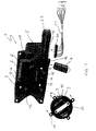
- a carrier element 1 designed as a central functional carrier 2, to which an electric adjustment drive 3, an entry lamp 4 and a concealed folding drive 5 can be attached.
- an electric adjustment drive 3, an entry lamp 4 and a concealed folding drive 5 can be attached.
- a plurality of conductor tracks 6 are provided on the carrier plate 2, the ends 7 of which are designed as plug-in tongues.
- the various are used to produce the central function carrier 2
- Conductor tracks 6 inserted into a mold cavity and extrusion-coated with plastic. For better visibility of the course of the conductor tracks 6 is the upper right corner of the central function carrier 2 is shown broken.
- the conductor tracks 6 are made of a rigid wire material manufactured, and are at the ends 7 kept in shape.
- the contacting elements 8, 9 and 10 on the adjustment drive 3 are so arranged that they during the assembly of the actuator 3 with the Attaching the retaining tabs 11 to the corresponding projections 12 the central function carrier 2 on the conductor tracks 13, 14 and 15 come to the system in an electrically conductive manner. That is, wiring the Adjustment drive 3 is no longer necessary, since with the joining movement a corresponding during the screwing of the adjustment drive 3 Plug contact between the individual contacting elements 8, 9 and 10, as well as 13, 14 and 15 is produced.
- the second ends 19 of the various conductor tracks 6 are on the Bottom of the central function carrier 2 in parallel next to each other arranged so that the multi-pin connector 20, which over the Wiring harness 21 can be connected to the vehicle electrical system in a linear joining movement can be simply plugged on.
- a not shown is shown on the actuator 22 of the adjustment drive 3 Glass assembly attached so that the reflection angle of the glass assembly remotely adjustable to the needs of the driver.
- the Fastening flange 23 becomes the central function carrier 2 on one Mirror foot, not shown, with the body of the motor vehicle is connectable, rotatably attached.
- a mirror housing, not shown covers the central function carrier 2 to the outside.
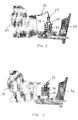
- Fig. 2 shows the central function carrier 2 in a broken cross section. It can be seen that the conductor tracks 6 are completely embedded in the plastic of the central function carrier 2. Only the ends of the conductor tracks 6 designed as tabs 7 protrude from the plastic of the central function carrier 2, so that they can be contacted electrically.
- FIG. 3 shows a carrier element according to the invention, which is designed as a central functional carrier 24 and is fastened rotatably mounted on a mirror base 25.
- the conductor tracks on the carrier element run in the central functional carrier and are therefore not recognizable in FIG. 3 .
- Flexible power cables 26 are connected to the ends of the individual conductor tracks, the first end of which is in contact with the conductor tracks and is surrounded by the material of the central function carrier 24 and the second end of which is connected to a contacting element of a multipole connector 27.
- the plug-in socket 30 which is functionally complementary to the plug connector 27 is arranged, so that after the central function carrier 24 has been fastened on the connecting element 28 of the mirror base 25, only the plug connector 27 in the socket 30 must be pressed.
- the multipole connector 33 on the carrier element 31 is designed such that it comes into contact with the connecting element 35 in the linearly from above to under joining movement for fastening the carrier element 31 to the mirror base 32 in the functionally complementary socket 34.
- the jack 34 in turn is connected to the electrical system of the motor vehicle via the lines 36.
Landscapes
- Engineering & Computer Science (AREA)
- Multimedia (AREA)
- Mechanical Engineering (AREA)
- Rear-View Mirror Devices That Are Mounted On The Exterior Of The Vehicle (AREA)
Applications Claiming Priority (2)
| Application Number | Priority Date | Filing Date | Title |
|---|---|---|---|
| DE19841551 | 1998-09-11 | ||
| DE19841551A DE19841551B4 (de) | 1998-09-11 | 1998-09-11 | Elektrischer Rückspiegel |
Publications (3)
| Publication Number | Publication Date |
|---|---|
| EP0985579A2 true EP0985579A2 (fr) | 2000-03-15 |
| EP0985579A3 EP0985579A3 (fr) | 2001-09-12 |
| EP0985579B1 EP0985579B1 (fr) | 2004-05-26 |
Family
ID=7880591
Family Applications (1)
| Application Number | Title | Priority Date | Filing Date |
|---|---|---|---|
| EP99117857A Expired - Lifetime EP0985579B1 (fr) | 1998-09-11 | 1999-09-10 | Rétroviseur extérieur électrique |
Country Status (3)
| Country | Link |
|---|---|
| US (1) | US6312135B1 (fr) |
| EP (1) | EP0985579B1 (fr) |
| DE (2) | DE19841551B4 (fr) |
Cited By (3)
| Publication number | Priority date | Publication date | Assignee | Title |
|---|---|---|---|---|
| EP1128986A1 (fr) | 1998-11-09 | 2001-09-05 | IKU Holding Montfoort B.V. | Retroviseur a commande electrique pour vehicule a moteur |
| DE10033088B4 (de) * | 2000-07-07 | 2005-12-22 | Bühler Motor GmbH | Aufschnappen des Spiegelantriebes |
| CN102310810A (zh) * | 2010-06-28 | 2012-01-11 | Smr专利责任有限公司 | 具有到后视镜壳体中的电气部件的电连接件的外部后视镜 |
Families Citing this family (34)
| Publication number | Priority date | Publication date | Assignee | Title |
|---|---|---|---|---|
| DE19952812C1 (de) | 1999-11-02 | 2001-08-16 | Hohe Gmbh & Co Kg | Außenrückspiegel mit Positionssensor |
| DE10022064A1 (de) | 2000-05-06 | 2001-11-08 | Bayerische Motoren Werke Ag | Außenspiegels eines Kraftfahrzeuges |
| DE10036592A1 (de) * | 2000-07-27 | 2002-02-07 | Reitter & Schefenacker Gmbh | Außenrückblickspiegel für Fahrzeuge, insbesondere Kraftfahrzeuge |
| DE10055319A1 (de) * | 2000-11-08 | 2002-05-16 | Buhler Motor Gmbh | Kraftfahrzeug-Rückblickspiegel |
| AUPR461301A0 (en) * | 2001-04-27 | 2001-05-24 | Schefenacker Vision Systems Australia Pty Ltd | Power fold mechanism for double arm mirrors |
| US7172298B2 (en) | 2001-04-27 | 2007-02-06 | Schefenacker Vision Systems Australia Pty Ltd | Power fold mechanism for vehicle mirrors |
| US6650457B2 (en) * | 2001-05-21 | 2003-11-18 | Gentex Corporation | Rearview mirror constructed for efficient assembly |
| DE20114989U1 (de) | 2001-09-11 | 2001-11-29 | FER Fahrzeugelektrik GmbH, 99817 Eisenach | Fahrzeugleuchte |
| DE20215068U1 (de) | 2002-09-27 | 2003-01-23 | Donnelly Hohe GmbH & Co. KG, 97903 Collenberg | Elektronisches Steuermodul zur Anordnung in einem Außenrückspiegel |
| US7244912B1 (en) * | 2003-09-11 | 2007-07-17 | Magna Donnelly Mirrors North America, L.L.C. | Vehicular mirror with heater circuit module |
| DE102004002554A1 (de) * | 2004-01-17 | 2005-08-11 | Daimlerchrysler Ag | Außenspiegel für ein Kraftfahrzeug |
| US20090244741A1 (en) * | 2008-03-31 | 2009-10-01 | Ford Global Technologies, Llc. | System, apparatus and method for active mirrors with blind spot detection |
| US20100220406A1 (en) * | 2008-03-31 | 2010-09-02 | Ford Global Technologies, Llc | Blind Spot Detection System |
| US11498486B2 (en) | 2009-10-07 | 2022-11-15 | Magna Mirrors Of America, Inc. | Vehicular exterior rearview mirror assembly |
| US9346403B2 (en) | 2009-10-07 | 2016-05-24 | Magna Mirrors Of America, Inc. | Rearview mirror assembly |
| US10261648B2 (en) | 2009-10-07 | 2019-04-16 | Magna Mirrors Of America, Inc. | Exterior rearview mirror assembly |
| US8915601B2 (en) | 2010-02-10 | 2014-12-23 | Magna Mirrors Of America, Inc. | Exterior mirror assembly with actuator |
| US11325535B2 (en) | 2010-02-10 | 2022-05-10 | Magna Mirrors Of America, Inc. | Exterior rearview mirror assembly |
| US12115913B2 (en) | 2010-02-10 | 2024-10-15 | Magna Mirrors Of America, Inc. | Vehicular exterior rearview mirror system |
| US10099618B2 (en) | 2014-02-12 | 2018-10-16 | Magna Mirrors Of America, Inc. | Exterior rearview mirror assembly |
| US9969334B2 (en) | 2010-02-10 | 2018-05-15 | Magna Mirrors Of America, Inc. | Exterior rearview mirror assembly |
| US9827913B2 (en) | 2010-02-10 | 2017-11-28 | Magna Mirrors Of America, Inc. | Exterior rearview mirror assembly |
| US9481304B2 (en) | 2010-05-24 | 2016-11-01 | Magna Mirrors Of America, Inc. | Automotive exterior mirror heater control |
| US9067541B2 (en) | 2011-10-31 | 2015-06-30 | Magna Mirrors Of America, Inc. | Exterior mirror assembly with actuator |
| US9242606B2 (en) | 2012-11-09 | 2016-01-26 | Magna Mirrors Of America, Inc. | Exterior mirror assembly with actuator |
| US9676336B2 (en) | 2013-06-25 | 2017-06-13 | Magna Mirrors Of America, Inc. | Exterior rearview mirror assembly for vehicle |
| US9487142B2 (en) | 2013-06-25 | 2016-11-08 | Magna Mirrors Of America, Inc. | Rearview mirror assembly for vehicle |
| US9796334B2 (en) | 2014-06-13 | 2017-10-24 | Magna Mirrors Of America, Inc. | Exterior rearview mirror assembly for vehicle |
| WO2019040711A1 (fr) | 2017-08-23 | 2019-02-28 | Magna Mirrors Of America, Inc. | Ensemble rétroviseur extérieur |
| WO2019226423A1 (fr) | 2018-05-24 | 2019-11-28 | Magna Mirrors Of America, Inc. | Ensemble rétroviseur extérieur |
| US11458895B2 (en) | 2020-04-27 | 2022-10-04 | Magna Mirrors Of America, Inc. | Exterior rearview mirror assembly |
| US12246648B2 (en) | 2021-01-19 | 2025-03-11 | Magna Mirrors Of America, Inc. | Vehicular exterior rearview mirror assembly with locking feature |
| CN117320921A (zh) | 2021-04-23 | 2023-12-29 | 麦格纳镜片美国有限公司 | 用于外部镜的电动折叠致动器 |
| US12351108B2 (en) | 2021-07-09 | 2025-07-08 | Magna Mirrors Of America, Inc. | Vehicular exterior rearview mirror assembly with extendable and retractable mirror head |
Family Cites Families (17)
| Publication number | Priority date | Publication date | Assignee | Title |
|---|---|---|---|---|
| DE3106792C2 (de) | 1981-02-24 | 1985-11-28 | Bayerische Motoren Werke AG, 8000 München | Elektrisch verstellbarer Außenrückblickspiegel an Kraftfahrzeugtüren |
| JPS58156432A (ja) | 1982-03-15 | 1983-09-17 | Secoh Giken Inc | 遠隔操作装置 |
| CH661808A5 (fr) * | 1985-01-21 | 1987-08-14 | Lupa Finances | Carte munie d'un microprocesseur et/ou d'au moins une memoire electronique. |
| US4941258A (en) * | 1988-05-06 | 1990-07-17 | United Technologies Automotive, Inc. | Method of electrically interconnecting door components to main power supply in vehicle |
| DE3844269A1 (de) * | 1988-12-30 | 1990-07-05 | Bosch Gmbh Robert | Scheinwerfer fuer kraftfahrzeuge |
| US4890908A (en) * | 1989-02-08 | 1990-01-02 | Casey Everett R | Readily attachable auxiliary wide angle outside rearview mirror |
| IT216962Z2 (it) * | 1989-03-07 | 1991-10-21 | Roltra Spa | Dispositivo di azionamento elettri co per uno specchio retrovisore e sterno di veicoli |
| US5455716A (en) * | 1990-08-14 | 1995-10-03 | Prince Corporation | Vehicle mirror with electrical accessories |
| DE4029890C2 (de) | 1990-09-21 | 1999-03-11 | Mekra Lang Gmbh & Co Kg | Rückblick-Einrichtung für Kraftfahrzeuge |
| DE4422572A1 (de) * | 1994-06-28 | 1996-01-04 | Reum Ag Metall U Kunststoffwer | Mittels Fernsteuerung verstellbarer Außenrückspiegel für Kraftfahrzeuge |
| DE4430700A1 (de) * | 1994-08-30 | 1996-03-07 | Teves Gmbh Alfred | In Motordeckel integrierter Schalter |
| JP3069263B2 (ja) | 1995-01-18 | 2000-07-24 | 株式会社村上開明堂 | 電動リモートコントロールミラーにおける駆動ユニットとハーネスとの接続構造 |
| DE19520320C1 (de) | 1995-06-02 | 1996-05-15 | Daimler Benz Ag | Außenrückspiegel für ein Kraftfahrzeug |
| DE29618937U1 (de) * | 1996-10-31 | 1997-01-02 | EM Kunststofftechnik GmbH, 07806 Neustadt | Außenrückblickspiegel für Kraftfahrzeuge |
| DE29620775U1 (de) * | 1996-11-29 | 1998-03-26 | Hohe GmbH & Co. KG, 97903 Collenberg | Außenspiegel für ein Fahrzeug |
| DE19724725C1 (de) * | 1997-06-12 | 1999-02-04 | Buhler Motor Gmbh | Vorrichtung zum elektrischen Einstellen des Innen- oder Außenspiegels eines Kraftfahrzeugs |
| DE29810522U1 (de) | 1998-06-10 | 1998-10-08 | Magna Reflex Holding GmbH, 97959 Assamstadt | Fahrzeugspiegel |
-
1998
- 1998-09-11 DE DE19841551A patent/DE19841551B4/de not_active Expired - Fee Related
-
1999
- 1999-09-10 US US09/394,970 patent/US6312135B1/en not_active Expired - Fee Related
- 1999-09-10 DE DE59909572T patent/DE59909572D1/de not_active Expired - Lifetime
- 1999-09-10 EP EP99117857A patent/EP0985579B1/fr not_active Expired - Lifetime
Non-Patent Citations (1)
| Title |
|---|
| None |
Cited By (5)
| Publication number | Priority date | Publication date | Assignee | Title |
|---|---|---|---|---|
| EP1128986A1 (fr) | 1998-11-09 | 2001-09-05 | IKU Holding Montfoort B.V. | Retroviseur a commande electrique pour vehicule a moteur |
| EP1128986B1 (fr) * | 1998-11-09 | 2003-10-08 | IKU Holding Montfoort B.V. | Retroviseur a commande electrique pour vehicule a moteur |
| DE10033088B4 (de) * | 2000-07-07 | 2005-12-22 | Bühler Motor GmbH | Aufschnappen des Spiegelantriebes |
| CN102310810A (zh) * | 2010-06-28 | 2012-01-11 | Smr专利责任有限公司 | 具有到后视镜壳体中的电气部件的电连接件的外部后视镜 |
| CN102310810B (zh) * | 2010-06-28 | 2014-01-22 | Smr专利责任有限公司 | 具有到后视镜壳体中的电气部件的电连接件的外部后视镜 |
Also Published As
| Publication number | Publication date |
|---|---|
| US6312135B1 (en) | 2001-11-06 |
| EP0985579A3 (fr) | 2001-09-12 |
| DE19841551B4 (de) | 2006-01-05 |
| DE59909572D1 (de) | 2004-07-01 |
| EP0985579B1 (fr) | 2004-05-26 |
| DE19841551A1 (de) | 2000-04-06 |
Similar Documents
| Publication | Publication Date | Title |
|---|---|---|
| EP0985579B1 (fr) | Rétroviseur extérieur électrique | |
| DE3889982T2 (de) | Kabelbaum. | |
| DE19653431C2 (de) | Dachinnenverkleidung für ein Kraftfahrzeug | |
| DE69705000T2 (de) | Kabelbaumstruktur in Kraftfahrzeugen | |
| DE4405083C2 (de) | Meßinstrumentenmodul | |
| DE4438461B4 (de) | Auskleidungsanschlußverbindung | |
| DE60006253T2 (de) | Instrumententafel und querträger dafür mit integralem flachkabelverbinder | |
| DE19654275C2 (de) | Montageanordnung zur Installation eines Elektrogerätemoduls | |
| DE19721452B4 (de) | Stromleiteranschlußanordnung für Automobiltüren | |
| DE3903818A1 (de) | Verdrahtungsvorrichtung fuer kraftfahrzeuge | |
| DE102008009080A1 (de) | Elektrischer Anschlusskasten | |
| DE10052163A1 (de) | Kabelbaumverteilungsstruktur für ein Fahrzeug | |
| EP2070311A1 (fr) | Systeme de camera modulaire | |
| DE3609609C2 (fr) | ||
| DE10157434B4 (de) | Schaltungsanordnung zum Steuern elektrischer Vorrichtungen in einem Fahrzeug | |
| EP1608994B1 (fr) | Ensemble capteur d'un systeme d'aide au stationnement | |
| EP2399781B1 (fr) | Rétroviseur extérieur doté d'une liaison électrique vers un composant électrique hébergé dans le boîtier du rétroviseur extérieur | |
| DE10033088B4 (de) | Aufschnappen des Spiegelantriebes | |
| DE4409183A1 (de) | Meßinstrumentenmodul und dessen elektrische Verbindungsvorrichtung | |
| DE19730343B4 (de) | Kraftfahrzeugtür mit einer Konstruktion zum Einbauen einer Leiteranordnung | |
| DE19718920C5 (de) | Leitungssatz für ein Kraftfahrzeug | |
| DE10037089A1 (de) | Befestigungsanordnung für eine flache Schaltanordnung | |
| DE102005044482A1 (de) | Flexible Flachbandleitung mit Elektronikbaugruppe | |
| DE69911990T2 (de) | Elektrisch gesteuerter kraftfahrzeug- rückblickspiegel | |
| DE69504389T2 (de) | Lenksäule für ein Kraftfahrzeug |
Legal Events
| Date | Code | Title | Description |
|---|---|---|---|
| PUAI | Public reference made under article 153(3) epc to a published international application that has entered the european phase |
Free format text: ORIGINAL CODE: 0009012 |
|
| AK | Designated contracting states |
Kind code of ref document: A2 Designated state(s): AT BE CH CY DE DK ES FI FR GB GR IE IT LI LU MC NL PT SE Kind code of ref document: A2 Designated state(s): DE FR GB |
|
| AX | Request for extension of the european patent |
Free format text: AL;LT;LV;MK;RO;SI |
|
| PUAL | Search report despatched |
Free format text: ORIGINAL CODE: 0009013 |
|
| AK | Designated contracting states |
Kind code of ref document: A3 Designated state(s): AT BE CH CY DE DK ES FI FR GB GR IE IT LI LU MC NL PT SE |
|
| AX | Request for extension of the european patent |
Free format text: AL;LT;LV;MK;RO;SI |
|
| RIC1 | Information provided on ipc code assigned before grant |
Free format text: 7B 60R 1/06 A, 7B 60R 1/07 B |
|
| 17P | Request for examination filed |
Effective date: 20011218 |
|
| AKX | Designation fees paid |
Free format text: DE FR GB |
|
| 17Q | First examination report despatched |
Effective date: 20030528 |
|
| GRAP | Despatch of communication of intention to grant a patent |
Free format text: ORIGINAL CODE: EPIDOSNIGR1 |
|
| GRAS | Grant fee paid |
Free format text: ORIGINAL CODE: EPIDOSNIGR3 |
|
| GRAA | (expected) grant |
Free format text: ORIGINAL CODE: 0009210 |
|
| AK | Designated contracting states |
Kind code of ref document: B1 Designated state(s): DE FR GB |
|
| REG | Reference to a national code |
Ref country code: GB Ref legal event code: FG4D Free format text: NOT ENGLISH |
|
| REF | Corresponds to: |
Ref document number: 59909572 Country of ref document: DE Date of ref document: 20040701 Kind code of ref document: P |
|
| GBT | Gb: translation of ep patent filed (gb section 77(6)(a)/1977) |
Effective date: 20040630 |
|
| ET | Fr: translation filed | ||
| PLBE | No opposition filed within time limit |
Free format text: ORIGINAL CODE: 0009261 |
|
| STAA | Information on the status of an ep patent application or granted ep patent |
Free format text: STATUS: NO OPPOSITION FILED WITHIN TIME LIMIT |
|
| 26N | No opposition filed |
Effective date: 20050301 |
|
| PGFP | Annual fee paid to national office [announced via postgrant information from national office to epo] |
Ref country code: FR Payment date: 20080917 Year of fee payment: 10 |
|
| PGFP | Annual fee paid to national office [announced via postgrant information from national office to epo] |
Ref country code: GB Payment date: 20080922 Year of fee payment: 10 |
|
| PGFP | Annual fee paid to national office [announced via postgrant information from national office to epo] |
Ref country code: DE Payment date: 20091127 Year of fee payment: 11 |
|
| GBPC | Gb: european patent ceased through non-payment of renewal fee |
Effective date: 20090910 |
|
| REG | Reference to a national code |
Ref country code: FR Ref legal event code: ST Effective date: 20100531 |
|
| PG25 | Lapsed in a contracting state [announced via postgrant information from national office to epo] |
Ref country code: FR Free format text: LAPSE BECAUSE OF NON-PAYMENT OF DUE FEES Effective date: 20090930 |
|
| PG25 | Lapsed in a contracting state [announced via postgrant information from national office to epo] |
Ref country code: GB Free format text: LAPSE BECAUSE OF NON-PAYMENT OF DUE FEES Effective date: 20090910 |
|
| REG | Reference to a national code |
Ref country code: DE Ref legal event code: R119 Ref document number: 59909572 Country of ref document: DE Effective date: 20110401 |
|
| PG25 | Lapsed in a contracting state [announced via postgrant information from national office to epo] |
Ref country code: DE Free format text: LAPSE BECAUSE OF NON-PAYMENT OF DUE FEES Effective date: 20110401 |