EP0985581A2 - Patère pour véhicules - Google Patents
Patère pour véhicules Download PDFInfo
- Publication number
- EP0985581A2 EP0985581A2 EP99116291A EP99116291A EP0985581A2 EP 0985581 A2 EP0985581 A2 EP 0985581A2 EP 99116291 A EP99116291 A EP 99116291A EP 99116291 A EP99116291 A EP 99116291A EP 0985581 A2 EP0985581 A2 EP 0985581A2
- Authority
- EP
- European Patent Office
- Prior art keywords
- hook
- closeout panel
- housing
- opening
- extended use
- Prior art date
- Legal status (The legal status is an assumption and is not a legal conclusion. Google has not performed a legal analysis and makes no representation as to the accuracy of the status listed.)
- Withdrawn
Links
- 230000007246 mechanism Effects 0.000 claims description 3
- 238000000034 method Methods 0.000 claims 5
- 238000010276 construction Methods 0.000 description 1
- 238000012986 modification Methods 0.000 description 1
- 230000004048 modification Effects 0.000 description 1
- 239000002991 molded plastic Substances 0.000 description 1
- 238000000465 moulding Methods 0.000 description 1
- 238000004806 packaging method and process Methods 0.000 description 1
- 230000000717 retained effect Effects 0.000 description 1
Images

Classifications
-
- B—PERFORMING OPERATIONS; TRANSPORTING
- B60—VEHICLES IN GENERAL
- B60R—VEHICLES, VEHICLE FITTINGS, OR VEHICLE PARTS, NOT OTHERWISE PROVIDED FOR
- B60R7/00—Stowing or holding appliances inside vehicle primarily intended for personal property smaller than suit-cases, e.g. travelling articles, or maps
- B60R7/08—Disposition of racks, clips, holders, containers or the like for supporting specific articles
- B60R7/10—Disposition of racks, clips, holders, containers or the like for supporting specific articles for supporting hats, clothes or clothes hangers
-
- Y—GENERAL TAGGING OF NEW TECHNOLOGICAL DEVELOPMENTS; GENERAL TAGGING OF CROSS-SECTIONAL TECHNOLOGIES SPANNING OVER SEVERAL SECTIONS OF THE IPC; TECHNICAL SUBJECTS COVERED BY FORMER USPC CROSS-REFERENCE ART COLLECTIONS [XRACs] AND DIGESTS
- Y10—TECHNICAL SUBJECTS COVERED BY FORMER USPC
- Y10T—TECHNICAL SUBJECTS COVERED BY FORMER US CLASSIFICATION
- Y10T24/00—Buckles, buttons, clasps, etc.
- Y10T24/34—Combined diverse multipart fasteners
- Y10T24/3401—Buckle
- Y10T24/3403—Buckle and buckles
Definitions
- the present invention relates to a coat hook assembly for a motor vehicle and in particular to a coat hook assembly having a closeout panel which covers the opening in a trim bezel when the coat hook is pulled out to a use position.
- coat hooks are often mounted to the vehicle body immediately above the rear door opening. This enables the vehicle driver to open the rear door and hang clothes on the coat hook by merely reaching into the vehicle.
- the coat hook can be attached to the headliner, the interior trim surrounding the door opening or directly to the vehicle body. In some vehicles the hook is part of a larger assembly containing an interior light and/or a grab handle for use by rear seat occupants.
- the coat hook is attached to a housing or bezel for movement from a retracted position in which the coat hook is substantially within the housing to an extending use position in which the hook projects from the housing and can be used to support a coat or hangers.
- a retracted position in which the coat hook is substantially within the housing
- an extending use position in which the hook projects from the housing and can be used to support a coat or hangers.
- an opening is revealed in the housing which was previously occupied by the hook. Within the fasteners and other attaching hardware for the housing may be visible when the coat hook is in the extended use position.
- the present invention accomplishes the above objection by providing a closeout panel which is operatively associated with the hook so that the closeout panel moves into a position closing the opening in the housing when the hook is rotated from its retracted position to its extended use position.
- the closeout panel is attached to the hook so that it moves upon rotation of the coat hook.
- the closeout panel is rotatably mounted to the coat hook and rotates relative to the coat hook upon rotation of the coat hook to its extended use position. This enables the hook and closeout panel to fold relative to one another to a compact position whereby they occupy less space in the housing when the coat hook is refracted.
- a guide between the housing and the closeout panel properly positions the closeout panel in the housing opening.
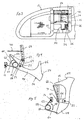
- the hook assembly of the present invention is shown in FIG. 1 as part of an interior hook and light assembly 10.
- the assembly 10 includes a housing or bezel 12, typically made of a molded plastic.
- the housing has a front face 14 which includes a light opening 16 and a hook opening 18.
- the light opening 16 is covered with a lens 20.
- An electric lamp (not shown) is disposed behind the lens 20 to provide interior lighting for a motor vehicle.
- a hook 24 is shown extending from the housing 12 in its extended use position.
- the housing 12 has rearward extending walls 26 about the opening 18.
- the walls 26 are formed with a pair of slots 30 which extend from the rear ends of the walls forward, toward the opening 18.
- the hook 24 includes a mounting portion 32 from which pivot pins 34 extend.
- the pivot pins 34 define a pivot axis 35.
- the pivot pins 34 are disposed within the slots 30 and positioned at the foreword ends of the slots 30, closest to the opening 18.
- a retainer 36 is used to hold the hook 24 in place.
- the retainer 36 is generally U-shaped and has a pair of legs 37. The legs 37 are inserted into the slots 30 behind the pivot pins 34 to capture the pivot pins 34 and thus attach the hook 24 to the housing.
- Screws 40 are inserted through apertures in the end wall 42 of the retainer 36 and into the rear face of the walls 26.
- the slots could be designed with detents to enable the pins 34 to snap into the slots and be retained without the use of a separate retainer.
- the hook 24 includes a hook arm 44 extending radially form the mounting portion 32.
- the hook arm has an upwardly extending lip 46 at the distal end thereof to retain hangers and coats placed on the hook arm 44.
- Also extending radially outward from the mounting portion 32 is a stop arm 48.
- the stop 52 is placed on end plate 51 attached by screws 53 to the wall 26 at the upper end of the opening 18.
- the end plate extends downward into the opening 18, reducing the opening height at the back of the housing 12 after the coat hook 24 has been installed.
- the end plate 51 presents the stop 52 at the proper height to engage the stop arm 48. With a different housing geometry, the end plate 51 may be eliminated.
- the stop 52 limits the rotation of the hook 24 into its extended use position.
- the distal end of the hook arm 44 is formed with a ledge 54.
- the ledge 54 engages the front face 14 of the housing at the upper end 55 of the opening 18 to form a rotation stop for the hook in its stowed position within the housing 12.
- the overcenter spring 56 biases the hook 24 to both its retracted position and its extended use position.
- the overcenter spring 56 is a torsional spring having a coil 58 and a pair of radially extending arms 60 and 62.
- the spring arm 60 is coupled to the stop arm 48 of the hook 24 near its distal end 50.
- the other spring arm 62 is attached to the housing 12.
- the spring force acts to separate the spring arms 60, 62 from one another as shown by the arrows 63 in FIGS. 4 and 5.
- the hook is shown in the retracted position in FIG. 5 in which the spring 56 urges the hook in a counter clockwise direction, forcing the ledge 54 against the housing front face 14. This holds the hook in the retracted position.
- the hook 24 also has a closeout panel mounting arm 64 which extends radially from the mounting portion 32 at approximately 90° relative to the hook arm 44.
- a closeout panel 66 is coupled to the mounting arm 64 by a pivot pin 67 for rotation of the closeout panel relative to the mounting arm 64.
- the pivot pin 67 defines a pivot axis 68 which is substantially parallel to the hook pivot axis 35 defined by the pivot pins 34.
- the closeout panel 66 In the retracted position of the hook 24, the closeout panel 66 is generally parallel to the hook arm 44 and nests within the bight defined by the hook arm 44 and the upwardly extending lip 46 at the distal end of the hook arm 44.
- the closeout panel 66 rotates relative to the hook 24 about the closeout panel pivot axis 68.
- a guide, in the form of a confinement wire 70, is operatively coupled to the closeout panel 66 and the housing 12, causing the closeout panel to rotate relative to the hook 24 as the hook 24 is rotated to the extended use position.
- the movement of the closeout panel 66 places the closeout panel in the hook opening 18 in the housing, thereby closing the opening when the hook 24 is in the extended use position.
- the closeout panel 66 has a T-shaped slot 72 which is open to the rear surface 74 of the closeout panel 66.
- the slot 72 extends from the distal end of the closeout panel 66 toward the pivot axis 68.
- the confinement wire 70 can be generally described as being U-shaped with unequal length legs 76, 78 and a cross bar 80 connecting the two legs 76, 78.
- the shorter leg 76 is placed within the T-slot 72 in the closeout panel 66.
- the longer leg 78 is attached to the wall 26 of the housing 12.
- the housing 12, the hook 24, the closeout panel 66 and confinement wire 70 form a 4-bar linkage. As shown in FIGS.
- the closeout panel when it moves into an operative position within the hook opening 18, is only slightly rotated relative to the orientation of the closeout panel when the hook is in the retracted position.
- Guide mechanisms other than the confinement wire 70, can be used to guide the movement of the closeout panel 66 from the retracted position to the operative position. Raised ribs or grooves in the housing wall can guide the closeout panel 66.
- closeout panel 66 has been shown rotatably coupled to the hook 24, it will be readily appreciated that a non-rotatable closeout panel, integrally formed with the hook 24 as a single piece molding, can perform the same function of closing the opening 18 in the housing.
- a non-rotatable closeout panel, integrally formed with the hook 24 as a single piece molding can perform the same function of closing the opening 18 in the housing.
- Such an integral closeout panel and hook would not require any form of guide to position it within the opening 18. Rather, the closeout panel would merely rotate with the hook and be held in position by the bias spring holding the hook in its extended use position.
- the only requirement for such a single piece hook and closeout panel is the necessary space within the housing, behind the front face 14 to contain the closeout panel which would extend further behind the front face 14 than the panel 66 described above. Depending upon the packaging space within the vehicle body, such a design may be feasible.
- the closeout panel 66 operates to close the opening 18 in the housing when the hook is in the extended use position. This prevents viewing of fasteners or other items in the interior of the housing and provides a more finished appearance to the vehicle interior.
Landscapes
- Engineering & Computer Science (AREA)
- Mechanical Engineering (AREA)
- Vehicle Step Arrangements And Article Storage (AREA)
Applications Claiming Priority (2)
| Application Number | Priority Date | Filing Date | Title |
|---|---|---|---|
| US152155 | 1993-11-15 | ||
| US09/152,155 US6095469A (en) | 1998-09-11 | 1998-09-11 | Coat hook assembly with closeout panel |
Publications (2)
| Publication Number | Publication Date |
|---|---|
| EP0985581A2 true EP0985581A2 (fr) | 2000-03-15 |
| EP0985581A3 EP0985581A3 (fr) | 2003-04-02 |
Family
ID=22541716
Family Applications (1)
| Application Number | Title | Priority Date | Filing Date |
|---|---|---|---|
| EP99116291A Withdrawn EP0985581A3 (fr) | 1998-09-11 | 1999-08-18 | Patère pour véhicules |
Country Status (2)
| Country | Link |
|---|---|
| US (1) | US6095469A (fr) |
| EP (1) | EP0985581A3 (fr) |
Cited By (4)
| Publication number | Priority date | Publication date | Assignee | Title |
|---|---|---|---|---|
| EP1332920A1 (fr) * | 2002-01-30 | 2003-08-06 | Trw Inc. | Patère escamotable |
| DE102008031011A1 (de) * | 2008-06-30 | 2009-12-31 | GM Global Technology Operations, Inc., Detroit | Grundplatte mit einem Kleiderhaken für ein Kraftfahrzeug |
| EP2305516A1 (fr) | 2009-10-02 | 2011-04-06 | M & M Srl | Dispositif de cintre modulaire pour vêtements |
| TWI392612B (zh) * | 2011-06-23 | 2013-04-11 | Kwang Yang Motor Co | The hook structure of the vehicle |
Families Citing this family (39)
| Publication number | Priority date | Publication date | Assignee | Title |
|---|---|---|---|---|
| US6397435B1 (en) * | 1999-04-22 | 2002-06-04 | Lear Corporation | Handle assembly with integrated hook |
| US6447055B1 (en) * | 1999-10-13 | 2002-09-10 | Magna Seating Systems Inc. | Combination grab handle and garment hook |
| US6315357B1 (en) * | 2000-08-22 | 2001-11-13 | Daimlerchrysler Corporation | Retractable garment hanger assembly |
| JP3733034B2 (ja) * | 2001-02-22 | 2006-01-11 | 株式会社ニフコ | アシストグリップ |
| DE10119604C1 (de) * | 2001-04-21 | 2002-10-31 | Porsche Ag | Innenausstattungsvorrichtung für ein Fahrzeug, insbesondere Kraftfahrzeug |
| US6422524B1 (en) | 2001-08-13 | 2002-07-23 | Johnson Controls Technology Company | Retractable nonlinear garment hook |
| US6643897B2 (en) * | 2001-10-23 | 2003-11-11 | Trw Inc. | Retractable grab handle and coat hook |
| US6457690B1 (en) * | 2001-11-26 | 2002-10-01 | Johnson Controls Technology Company | Vehicle accessory combined hook and clip |
| US6523888B1 (en) * | 2002-01-04 | 2003-02-25 | Honda Giken Kogyo Kabushiki Kaisha | Integrated light and grab rail assembly |
| US6715813B2 (en) * | 2002-08-20 | 2004-04-06 | Johnson Controls Technology | Over-center spring control |
| US6789773B2 (en) | 2002-09-23 | 2004-09-14 | Adstracts, Inc. | Article support apparatus with movable display panel |
| US6959954B2 (en) * | 2002-10-29 | 2005-11-01 | Intier Automotive Inc. | Vehicle trim component with self retaining fastening device |
| US6968601B2 (en) * | 2003-02-07 | 2005-11-29 | Illinois Tool Works Inc | Coat hook system with integral damper and latch |
| DE10330037B3 (de) * | 2003-07-03 | 2005-01-20 | Infineon Technologies Ag | Adapterkarte zum Anschließen an einen Datenbus in einer Datenverarbeitungseinheit und Verfahren zum Betreiben eines DDR-Speichermoduls |
| US7270359B2 (en) | 2003-07-07 | 2007-09-18 | Johnson Controls Technology Company | Assist handle assembly with accessories |
| USD489251S1 (en) | 2003-07-21 | 2004-05-04 | Charles Ay | Hanging apparatus |
| US6991204B2 (en) * | 2003-07-21 | 2006-01-31 | Charles Ay | Recessed hanging apparatus |
| JP3966842B2 (ja) * | 2003-08-25 | 2007-08-29 | 株式会社パイオラックス | 開閉制動装置 |
| US7219868B2 (en) * | 2004-09-13 | 2007-05-22 | Rec Enterprises, Ltd | Hook device for attachment to tables and the like |
| US7234672B1 (en) * | 2005-02-25 | 2007-06-26 | Osterholt Lana M | Retractable hanger |
| DE102006034182A1 (de) * | 2006-07-24 | 2008-02-07 | Siemens Ag | Ablagefach |
| US7669821B2 (en) * | 2007-10-02 | 2010-03-02 | Honda Motor Co., Ltd | Retractable accessory hook for a vehicle |
| US20090266858A1 (en) * | 2008-04-28 | 2009-10-29 | Vander Sluis Daniel R | Glove box door tethered utility hook |
| JP5897875B2 (ja) * | 2011-11-15 | 2016-04-06 | 株式会社パイオラックス | 車両用フック装置 |
| US8827516B2 (en) | 2011-11-30 | 2014-09-09 | Ford Global Technologies, Llc | Modular grab handle with integral lamp attaching system |
| US8733830B2 (en) * | 2012-02-23 | 2014-05-27 | Roy C Sanchez | Headrest hat hook retractable side hanger |
| US9561755B2 (en) | 2012-08-01 | 2017-02-07 | Ford Global Technologies, Llc | Vehicle garment hook assembly |
| US8820597B2 (en) * | 2012-08-01 | 2014-09-02 | Ford Global Technologies, Llc | Vehicle garment hook and guard mounting assembly |
| JP5970133B2 (ja) * | 2013-06-13 | 2016-08-17 | 株式会社パイオラックス | フック装置 |
| US9931991B2 (en) | 2013-11-21 | 2018-04-03 | Ford Global Technologies, Llc | Rotating garment hook |
| US9079542B1 (en) | 2014-01-28 | 2015-07-14 | Ford Global Technologies, Llc | Retractable vehicle grab handle with deploying integrated garment hanger |
| US9725032B2 (en) | 2014-10-13 | 2017-08-08 | Ford Global Technologies, Llc | Integrated coat hook and light source assembly |
| GB2547170B (en) * | 2014-12-05 | 2020-07-22 | Piolax Inc | Retaining device |
| US9604579B2 (en) | 2015-08-17 | 2017-03-28 | Ford Global Technologies, Llc | Illuminated coat hook to assist in locating coat hook in the dark |
| US9731657B1 (en) | 2016-07-15 | 2017-08-15 | Ford Global Technologies, Llc | Vehicle hanger and illumination assembly |
| US10220790B2 (en) * | 2017-01-26 | 2019-03-05 | Ford Global Technologies, Llc | Pivoting hanger with positive retention |
| US10065565B2 (en) | 2017-01-26 | 2018-09-04 | Ford Global Technologies, Llc | Linear-travel hanger assembly |
| US10544897B2 (en) * | 2017-07-10 | 2020-01-28 | Liuba Nesin | Folding wall bracket |
| US10363880B1 (en) | 2018-03-07 | 2019-07-30 | Ford Global Technologies, Llc | Vehicle seat assembly having deployable hanger |
Family Cites Families (13)
| Publication number | Priority date | Publication date | Assignee | Title |
|---|---|---|---|---|
| US338677A (en) * | 1886-03-23 | Clothes-hook | ||
| US2390257A (en) * | 1944-08-21 | 1945-12-04 | Walter K Jahn | Disappearing hanger |
| US3385547A (en) * | 1966-12-14 | 1968-05-28 | Gen Motors Corp | Vehicle body coat hook |
| US3424418A (en) * | 1967-02-14 | 1969-01-28 | Ford Motor Co | Automatically retractable coat hook |
| US4221354A (en) * | 1978-11-22 | 1980-09-09 | Prince Corporation | Retractable hook for a vehicle |
| US4444344A (en) * | 1982-09-23 | 1984-04-24 | Prince Corporation | Hanger support |
| JPS61190730U (fr) * | 1985-04-19 | 1986-11-27 | ||
| US5411233A (en) * | 1993-01-21 | 1995-05-02 | Prince Corporation | Vehicle coat hook assembly |
| DE9405306U1 (de) * | 1994-03-29 | 1994-06-16 | Utescheny-Endos GmbH, 75059 Zaisenhausen | Kleiderhakeneinrichtung, bevorzugt für den Innenraum von Fahrzeugen |
| US5507423A (en) * | 1995-02-28 | 1996-04-16 | Prince Corporation | Push-push vehicle clothes hook assembly |
| US5829725A (en) * | 1996-06-21 | 1998-11-03 | Russo; David A. | Garment hanger bracket for automotive garment hangers |
| DE29614470U1 (de) * | 1996-08-21 | 1996-10-02 | Utescheny-Endos GmbH, 75059 Zaisenhausen | Kleiderhakeneinrichtung, insbesondere für den Innenraum von Fahrzeugen |
| USD403998S (en) | 1997-05-20 | 1999-01-12 | Lear Donnelly Overhead Systems L.L.C. | Vehicular coat hook unit |
-
1998
- 1998-09-11 US US09/152,155 patent/US6095469A/en not_active Expired - Fee Related
-
1999
- 1999-08-18 EP EP99116291A patent/EP0985581A3/fr not_active Withdrawn
Non-Patent Citations (1)
| Title |
|---|
| None |
Cited By (5)
| Publication number | Priority date | Publication date | Assignee | Title |
|---|---|---|---|---|
| EP1332920A1 (fr) * | 2002-01-30 | 2003-08-06 | Trw Inc. | Patère escamotable |
| US6663067B2 (en) | 2002-01-30 | 2003-12-16 | Trw Inc. | Retractable coat hook |
| DE102008031011A1 (de) * | 2008-06-30 | 2009-12-31 | GM Global Technology Operations, Inc., Detroit | Grundplatte mit einem Kleiderhaken für ein Kraftfahrzeug |
| EP2305516A1 (fr) | 2009-10-02 | 2011-04-06 | M & M Srl | Dispositif de cintre modulaire pour vêtements |
| TWI392612B (zh) * | 2011-06-23 | 2013-04-11 | Kwang Yang Motor Co | The hook structure of the vehicle |
Also Published As
| Publication number | Publication date |
|---|---|
| EP0985581A3 (fr) | 2003-04-02 |
| US6095469A (en) | 2000-08-01 |
Similar Documents
| Publication | Publication Date | Title |
|---|---|---|
| US6095469A (en) | Coat hook assembly with closeout panel | |
| US6062623A (en) | Latch for vehicle overhead storage bin | |
| US4552399A (en) | Glove box on vehicular instrument panel | |
| KR930006999B1 (ko) | 덮개체의 개폐장치 | |
| US4943109A (en) | Automotive door assembly having a plug-in electrified interior panel | |
| JP3451156B2 (ja) | 自動車の天井用小物入れ | |
| JP2501422Y2 (ja) | 自動車用ドア | |
| US6422524B1 (en) | Retractable nonlinear garment hook | |
| US10780835B2 (en) | Integral foldable hook arrangement | |
| US6715813B2 (en) | Over-center spring control | |
| EP3342647A1 (fr) | Portière de véhicule | |
| JPH11165591A (ja) | オーバーヘッドコンソール | |
| US10988962B2 (en) | Retractable outside handle assembly for vehicle | |
| US5039153A (en) | Pivot down vanity mirror assembly | |
| EP3072745B1 (fr) | Ensemble de stockage de véhicules | |
| US7331625B2 (en) | Garment hook assembly | |
| US8764093B2 (en) | Fixture for a component and a fixture mount | |
| JP4410958B2 (ja) | 車両用ルーフコンソール装置 | |
| JPH0376253B2 (fr) | ||
| JP6714843B2 (ja) | 車両用ドアトリム | |
| JP3472150B2 (ja) | 自動車のドアアウトサイドハンドル装置 | |
| US20060096176A1 (en) | Closing device | |
| JP6642829B2 (ja) | 車両用ドア | |
| US20050253399A1 (en) | Lock device for glove compartment | |
| JP2000025506A (ja) | 自動車用インストルメントパネルの助手席テーブル取付構造 |
Legal Events
| Date | Code | Title | Description |
|---|---|---|---|
| PUAI | Public reference made under article 153(3) epc to a published international application that has entered the european phase |
Free format text: ORIGINAL CODE: 0009012 |
|
| AK | Designated contracting states |
Kind code of ref document: A2 Designated state(s): AT BE CH CY DE DK ES FI FR GB GR IE IT LI LU MC NL PT SE |
|
| AX | Request for extension of the european patent |
Free format text: AL;LT;LV;MK;RO;SI |
|
| RAP1 | Party data changed (applicant data changed or rights of an application transferred) |
Owner name: JOHNSON CONTROLS TECHNOLOGY COMPANY |
|
| RAP1 | Party data changed (applicant data changed or rights of an application transferred) |
Owner name: JOHNSON CONTROLS TECHNOLOGY COMPANY |
|
| PUAL | Search report despatched |
Free format text: ORIGINAL CODE: 0009013 |
|
| AK | Designated contracting states |
Kind code of ref document: A3 Designated state(s): AT BE CH CY DE DK ES FI FR GB GR IE IT LI LU MC NL PT SE Designated state(s): AT BE CH CY DE DK ES FI FR GB GR IE IT LI LU MC NL PT SE |
|
| AX | Request for extension of the european patent |
Extension state: AL LT LV MK RO SI |
|
| AKX | Designation fees paid |
Designated state(s): DE ES FR GB IT |
|
| STAA | Information on the status of an ep patent application or granted ep patent |
Free format text: STATUS: THE APPLICATION IS DEEMED TO BE WITHDRAWN |
|
| 18D | Application deemed to be withdrawn |
Effective date: 20031005 |