EP0985614A2 - Vorrichtung zum Transport von plattenförmigem Transportgut - Google Patents
Vorrichtung zum Transport von plattenförmigem Transportgut Download PDFInfo
- Publication number
- EP0985614A2 EP0985614A2 EP99117535A EP99117535A EP0985614A2 EP 0985614 A2 EP0985614 A2 EP 0985614A2 EP 99117535 A EP99117535 A EP 99117535A EP 99117535 A EP99117535 A EP 99117535A EP 0985614 A2 EP0985614 A2 EP 0985614A2
- Authority
- EP
- European Patent Office
- Prior art keywords
- carriage
- support element
- transport
- frame
- goods
- Prior art date
- Legal status (The legal status is an assumption and is not a legal conclusion. Google has not performed a legal analysis and makes no representation as to the accuracy of the status listed.)
- Withdrawn
Links
Images


Classifications
-
- B—PERFORMING OPERATIONS; TRANSPORTING
- B65—CONVEYING; PACKING; STORING; HANDLING THIN OR FILAMENTARY MATERIAL
- B65H—HANDLING THIN OR FILAMENTARY MATERIAL, e.g. SHEETS, WEBS, CABLES
- B65H5/00—Feeding articles separated from piles; Feeding articles to machines
- B65H5/04—Feeding articles separated from piles; Feeding articles to machines by movable tables or carriages
-
- B—PERFORMING OPERATIONS; TRANSPORTING
- B65—CONVEYING; PACKING; STORING; HANDLING THIN OR FILAMENTARY MATERIAL
- B65G—TRANSPORT OR STORAGE DEVICES, e.g. CONVEYORS FOR LOADING OR TIPPING, SHOP CONVEYOR SYSTEMS OR PNEUMATIC TUBE CONVEYORS
- B65G47/00—Article or material-handling devices associated with conveyors; Methods employing such devices
- B65G47/74—Feeding, transfer, or discharging devices of particular kinds or types
- B65G47/90—Devices for picking-up and depositing articles or materials
- B65G47/91—Devices for picking-up and depositing articles or materials incorporating pneumatic, e.g. suction, grippers
- B65G47/918—Devices for picking-up and depositing articles or materials incorporating pneumatic, e.g. suction, grippers with at least two picking-up heads
-
- B—PERFORMING OPERATIONS; TRANSPORTING
- B65—CONVEYING; PACKING; STORING; HANDLING THIN OR FILAMENTARY MATERIAL
- B65G—TRANSPORT OR STORAGE DEVICES, e.g. CONVEYORS FOR LOADING OR TIPPING, SHOP CONVEYOR SYSTEMS OR PNEUMATIC TUBE CONVEYORS
- B65G57/00—Stacking of articles
- B65G57/02—Stacking of articles by adding to the top of the stack
- B65G57/03—Stacking of articles by adding to the top of the stack from above
- B65G57/04—Stacking of articles by adding to the top of the stack from above by suction or magnetic devices
-
- B—PERFORMING OPERATIONS; TRANSPORTING
- B65—CONVEYING; PACKING; STORING; HANDLING THIN OR FILAMENTARY MATERIAL
- B65H—HANDLING THIN OR FILAMENTARY MATERIAL, e.g. SHEETS, WEBS, CABLES
- B65H5/00—Feeding articles separated from piles; Feeding articles to machines
- B65H5/08—Feeding articles separated from piles; Feeding articles to machines by grippers, e.g. suction grippers
- B65H5/10—Reciprocating or oscillating grippers, e.g. suction or gripper tables
-
- B—PERFORMING OPERATIONS; TRANSPORTING
- B65—CONVEYING; PACKING; STORING; HANDLING THIN OR FILAMENTARY MATERIAL
- B65H—HANDLING THIN OR FILAMENTARY MATERIAL, e.g. SHEETS, WEBS, CABLES
- B65H5/00—Feeding articles separated from piles; Feeding articles to machines
- B65H5/26—Duplicate, alternate, selective, or coacting feeds
-
- B—PERFORMING OPERATIONS; TRANSPORTING
- B65—CONVEYING; PACKING; STORING; HANDLING THIN OR FILAMENTARY MATERIAL
- B65H—HANDLING THIN OR FILAMENTARY MATERIAL, e.g. SHEETS, WEBS, CABLES
- B65H2403/00—Power transmission; Driving means
- B65H2403/50—Driving mechanisms
- B65H2403/55—Tandem; twin or multiple mechanisms, i.e. performing the same operation
-
- B—PERFORMING OPERATIONS; TRANSPORTING
- B65—CONVEYING; PACKING; STORING; HANDLING THIN OR FILAMENTARY MATERIAL
- B65H—HANDLING THIN OR FILAMENTARY MATERIAL, e.g. SHEETS, WEBS, CABLES
- B65H2406/00—Means using fluid
- B65H2406/30—Suction means
- B65H2406/34—Suction grippers
- B65H2406/342—Suction grippers being reciprocated in a rectilinear path
Definitions
- the invention relates to a device according to the preamble of claim 1. It also relates to a method of transportation of plate-shaped transport goods, such as metal sheets or blanks, with the device.
- Such a device is known from G 69 18 642.1.
- the known device is provided with a suction cup Conveyor belt continuously around the conveyor belt supporting frame moves.
- a suction cup Conveyor belt continuously around the conveyor belt supporting frame moves.
- the cargo describes after it has been dropped a parabolic trajectory from the suction cup.
- the known device has the disadvantage that it only transported goods in the direction of transport, but not against the direction of transport can be moved.
- the object of the invention is an apparatus and a method specify the disadvantages according to the state of the Technology to be eliminated.
- should be a procedure and a device is provided, which one as possible wear-free transport both in and against enable a direction of transport.
- the Production of precise stacks without special stacking aid become.
- a first Carrying element on a first carriage received on the frame and a second support element on one received on the frame attached second carriage and a device for simultaneous Moving the first and second slides in opposite directions is provided.
- the device is largely wear-free Transport of goods to be transported as well as manufacturing more precisely Stack possible. The goods can be transported both in and against the direction of transport.
- the first carriage is advantageously in one on the frame provided first and second slides in one on the frame provided second rail.
- the rails are preferably straight.
- the slide provided guide element can be the first or grasp the second rail behind the handle.
- the guide element advantageously has at least two opposite one another Wheels on, the tread in cross section each forms a groove.
- one is from the first Carriage extending first fastener on Upper run and one extending from the second carriage second fastener on the lower strand one around the frame guided connecting means attachable.
- the first and second fasteners can be one have controllable clamping device. So it is possible e.g. computer-controlled, the arrangement of the two sections to each other to change the lanyard.
- the lanyard which is a strap, a rope or a Chain can act, is expedient to end on Frame attached rollers performed, at least one of the Rollers attached to an electric motor driven shaft can be.
- first and / or second carriage means for moving the first or second support element perpendicular to the linear direction of movement the sledge has.
- the means of moving can a pneumatically, hydraulically or electromotively operated Have actuator.
- the actuator is expediently shown in three predetermined positions can be moved. It can be a damage-protected close to the slide Position, a middle transport position and one removed Position from the sled for picking up or delivering to deal with transport goods.
- the first one and the second support element each has at least one with one Device for generating vacuum connected suction cup and / or an electrically switchable magnet.
- the first and second sled can also be one Have a plurality of first or second support elements.
- the combination of magnets and suction cups in one Sled is useful because it can transport both magnetic as well as non-magnetic goods to be transported becomes. It is considered advantageous that the first Sled two first suction cups and the second sled two have second suction cups.
- the movement the shaft with the movement of one against the direction of transport upstream means of producing the goods to be transported correlated.
- the remedy can be, for example act as a punching tool, the cycle speed with the speed of the shaft is correlated so that alternately from first and second support element the transported goods can be picked up and transported further.
- the steps lit. a and lit. b can of course also be carried out in the reverse order.
- the default Stop position can be at one end of the path of movement.
- the goods to be transported are advantageously recorded at the other end of the movement path.
- the first or second support element is advantageously before, during or after step lit. e move to the first position.
- the goods can be transported on an already existing one Stack are pressed.
- the formation of an air cushion between the stack and the stored goods avoided. This makes stack formation particularly precise enables.
- the first or second support element is after step lit. e into a second one close to the first or second slide Move position. This will make the encounter damage to a loaded with an unloaded sled of the support element (s) of the unladen carriage and reliably avoided.
- the first or second support element can after the step lit. c are moved to a third position between the first and second positions. At this middle position is advantageously a Transport position. In this position there is a collision with a stack located at the end of the movement path is impossible.
- another can be specified Stop position in the middle of the movement path.
- the second or first support element from the second in put the third position and pressurized be so that the goods to be transported from the first or second the second or first support element is transferred. It is for that of course, required on the cargo take away the acting force of the releasing supporting element and it expediently to return to the second position. Then can the second or first carriage in the holding position be moved.
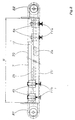
- Fig. 1 is one consisting of two identical devices Transport device shown in cross section.
- the two Devices are on a mounting frame (not shown here) held.
- Each of the devices has one, preferably frame 1 made from an aluminum profile, a first 2a and a second offset in height along its long sides Rail 2b are attached.
- the first 2a and second rail 2b are just formed here. They have an underhanded Profile on.
- the rails 2a, 2b can be made from an extruded one Be made of plastic profile, the tread from a metal rod inserted into the plastic profile 3 can be formed.
- a first 4a and a second Carriages 4b are by means of the first 2a and second rails 2b behind gripping wheels 5 guided.
- first carriage 4a extends parallel to the lower one Narrow side of the frame 1 movable first fastener 6a; extends from the second carriage 4b movable parallel to the upper narrow side of the frame 1 second fastener 6b.
- the first fastener 6a is clamped to the lower run TU of a belt 7 and that second fastening element 6b is clamped to the upper run TO Belt 7 attached.
- the clamping connection can if necessary by a controllable (not shown here) Clamping device released and then restored be so that the position of the carriage 4a, 4b to each other is changeable.
- a first 8a and a second cable duct 8b are attached to a web 9 extending from the frame 1.
- the first 8a and second cable duct 8b are each of a first 10a attached to the first carriage 4a and one second mudguard 10b attached to the second carriage 4b partially encompassed.
- a first suction cup 11a is on a first actuator 12a fastened vertically; is a second suction cup 11b vertically movable attached to a second actuator 12b.
- the first suction cup 11a is located in a first one Position P1, which is distant from the first carriage 4a.
- the second suction cup 11b is located in one close to the second Carriage 4b located second position P2. All Adhesive surfaces of the support elements designed as suction cups 11a, 11b can be moved to the same level.
- FIG. 2 shows a schematic side view of the first device.
- the distance between the first two 4a and the two second slides 4b is the same.
- With B is the length of the movement path.
- the belt 7, at which can preferably be a toothed belt, is guided around a first R1 and a second roller R2.
- a of the two roles R1, R2 is with a (not shown here) Shaft connected by a reversible electric motor is driven.
- the belt is rotating an opposite movement of the first 4a and the second carriage 4b caused, the two Encounter sled 4a, 4b.
- 3a to 3e is a schematic of the transport of a Sheet metal shown by a second device.
- the distance between the first carriage 4a and second carriage 4b is chosen so that one of the first 4a and one of the second slides 4b in opposite Arrangement if the other first 4a or other second slides 4b each at the end of the movement path B stand.
- T the transport direction, with TG a plate-shaped one Designated cargo.
- the second suction cups 11b move in the second position P2.
- the vacuum supply is interrupted and the cargo TG on one in the second Holding position stored stack.
- the first suction cups 11a of the in opposite position of the first carriage 4a Move from the first P1 to the third position P3 and with Vacuum applied.
- the application of the second suction cups 11b with negative pressure is interrupted.
- the second suction cups 11b are moved into the first position P1.
- the belt 7 is then half Length of movement path B moves.
- the the cargo TG carrying first suction cups 11a reach the first stop position H1.
- the first suction cups are used to deliver the goods 11a move to the second position P2.
- the pressurization will be interrupted. After that, the first Move suction cups 11a to the first position P1. Subsequently can the first suction cups 11a by moving the Belt 7 in the transport direction T again in that shown in Fig. 3b Starting position will be retracted.
- 3e schematically shows the sequence of movements of the second 11b and first suction cups 11a when transporting a transport good TG shown in the first stop position H1.
- the first position is with P1, the second position with P2 and the third Position labeled P3.
Landscapes
- Engineering & Computer Science (AREA)
- Mechanical Engineering (AREA)
- Sheets, Magazines, And Separation Thereof (AREA)
- Specific Conveyance Elements (AREA)
- Advancing Webs (AREA)
Abstract
Description
- Fig. 1
- eine schematische Querschnittsansicht einer ersten Vorrichtung,
- Fig. 2
- eine schematische Seitenansicht der ersten Vorrichtung,
- Fig. 3a bis 3e
- den Transport eines Blechs mittels einer zweiten Vorrichtung.
- 1
- Rahmen
- 2a, 2b
- erste, zweite Schiene
- 3
- Metallstab
- 4a, 4b
- erster, zweiter Schlitten
- 5
- Rad
- 6a, 6b
- erstes, zweites Befestigungselement
- 7
- Riemen
- 8a, 8b
- erster, zweiter Kabelkanal
- 9
- Steg
- 10a, 10b
- erstes, zweites Schutzblech
- 11a, 11b
- erster, zweiter Saugnapf
- 12a, 12b
- erstes, zweites Stellglied
- T
- Transportrichtung
- TO
- Obertrum
- TU
- Untertrum
- TG
- Transportgut
- H1
- erste Halteposition
- H2
- zweite Halteposition
- A
- Aufnahmeposition
- R1
- erste Rolle
- R2
- zweite Rolle
- B
- Bewegungsweg
- P1
- erste Position
- P2
- zweite Position
- P3
- dritte Position
Claims (24)
- Vorrichtung zum Transport von plattenförmigem Transportgut (TG), wie Blechen oder Platinen, mit einem Rahmen (1) und mindestens zwei entlang des Rahmens (1) bewegbaren Tragelementen (11a, 11b), dadurch gekennzeichnet, daß ein erstes Tragelement (11a) an einem am Rahmen (1) aufgenommenen ersten Schlitten (4a) und ein zweites Tragelement (11b) an einem am Rahmen (1) aufgenommenen zweiten Schlitten (4b) angebracht und eine Einrichtung (R1, R2, 6a, 6b, 7) zum gleichzeitigen Bewegen des ersten (4a) und des zweiten Schlittens (4b) in entgegengesetzte Richtungen vorgesehen ist.
- Vorrichtung nach Anspruch 1, wobei der erste Schlitten (4a) in einer am Rahmen (1) vorgesehenen ersten (2a) und der zweite Schlitten (4b) in einer am Rahmen (1) vorgesehenen zweiten Schiene (2b) geführt ist, wobei die Schienen (2a, 2b) vorzugsweise gerade ausgebildet sind.
- Vorrichtung nach einem der vorhergehenden Ansprüche, wobei ein am ersten (4a) und/oder zweiten Schlitten (4b) vorgesehenes Führungselement (5) die erste bzw. zweite Schiene (2b) hintergriffig umgreift.
- Vorrichtung nach einem der vorhergehenden Ansprüche, wobei ein vom ersten Schlitten (4a) sich erstreckendes erstes Befestigungselement (6a) am Untertrum (TU) und ein vom zweiten Schlitten (4b) sich erstreckendes zweites Befestigungselement (6b) am Obertrum (TO) eines um den Rahmen (1) geführten Verbindungsmittels (7) befestigbar ist.
- Vorrichtung nach einem der vorhergehenden Ansprüche, wobei das erste (6a) und das zweite Befestigungselement (6b) eine steuerbare Klemmvorrichtung aufweisen.
- Vorrichtung nach einem der vorhergehenden Ansprüche, wobei das Verbindungsmittel (7) um endständig am Rahmen (1) angebrachte Rollen (R1, R2) geführt ist.
- Vorrichtung nach einem der vorhergehenden Ansprüche, wobei mindestens eine der Rollen (R1, R2) auf einer elektromotrisch angetriebenen Welle angebracht ist.
- Vorrichtung nach einem der vorhergehenden Ansprüche, wobei der erste (4a) und/oder zweite Schlitten (4b) ein Mittel zum Bewegen des ersten bzw. zweiten Tragelements (11a, 11b) senkrecht zur Bewegungsrichtung (T) der Schlitten (4a, 4b) aufweist/aufweisen.
- Vorrichtung nach einem der vorhergehenden Ansprüche, wobei das Mittel zum Bewegen ein pneumatisch, hydraulisch oder elektromotorisch betätigtes Stellglied (12a, 12b) aufweist.
- Vorrichtung nach einem der vorhergehenden Ansprüche, wobei das Stellglied (12a, 12b) in drei vorgegebene Positionen (P1, P2, P3) verfahrbar ist.
- Vorrichtung nach einem der vorhergehenden Ansprüche, wobei das erste (11a) und das zweite Tragelement (11b) jeweils mindestens einen mit einer Einrichtung zur Erzeugung von Unterdruck verbundenen Saugnapf und/oder einen elektrisch schaltbaren Magneten aufweisen.
- Vorrichtung nach einem der vorhergehenden Ansprüche, wobei der erste Schlitten (4a) zwei erste Saugnäpfe (11a) und der zweite Schlitten (4b) zwei zweite Saugnäpfe (11b) aufweist.
- Vorrichtung nach einem der vorhergehenden Ansprüche, wobei am Untertrum (TU) des Verbindungsmittels (7) zwei erste Schlitten (4a) und am Obertrum (TO) des Verbindungsmittels (7) zwei zweite Schlitten (4b) jeweils im Abstand der halben Länge eines Bewegungswegs (B) befestigt sind.
- Transporteinrichtung zum Transport von plattenförmigem Transportgut (TG), wie Blechen oder Platinen, wobei mehrere Vorrichtungen nach einem der vorhergehenden Ansprüche nebeneinander an einem Aufnahmerahmen gehalten sind.
- Transporteinrichtung nach Anspruch 14, wobei eine gemeinsame Welle zum Antrieb einer der Rollen (R1, R2) jeder Vorrichtung vorgesehen ist.
- Verfahren zum Transport von plattenförmigem Transportgut (TG), wie Blechen oder Platinen, mit einer Vorrichtung nach einem der vorhergehenden Ansprüche umfassend die folgenden Schritte:a) Verfahren des ersten (11a) bzw. zweiten Tragelements (11b) in eine vom ersten Schlitten (4a) entfernte erste Position (P1),b) Erzeugen einer vom ersten (11a) bzw. zweiten Tragelement (11b) ausgehenden auf das Transportgut (TG) wirkenden Kraft,c) Aufnahme des Transportguts am ersten bzw. zweiten Tragelement (11a, 11b),d) Bewegen des ersten (4a) bzw. zweiten Schlittens (4b) entlang dem Bewegungsweg (B) bis zu einer vorgegebenen Halteposition (H1, H2) unde) Wegnehmen der vom ersten bzw. zweiten Tragelement (11a, 11b) auf das Transportgut (TG) wirkenden Kraft.
- Verfahren nach Anspruch 16, wobei die vorgegebene Halteposition (H1) am einen Ende des Bewegungswegs (B) sich befindet.
- Verfahren nach Anspruch 16 oder 17, wobei das erste (11a) bzw. zweite Tragelement (11b) vor oder während dem Schritt lit. e in die erste Position (P1) verfahren wird.
- Verfahren nach einem der Ansprüche 16 bis 18, wobei das erste (11a) bzw. zweite Tragelement (11b) nach dem Schritt lit. e in eine nahe am ersten (4a) bzw. zweiten Schlitten (4b) befindliche zweite Position (P2) verfahren wird.
- Verfahren nach einem der Ansprüche 16 bis 19, wobei das erste (11a) bzw. zweite Tragelement (11b) nach dem Schritt lit. c in eine dritte Position (P3) verfahren wird, die zwischen der ersten (P1) und der zweiten Position (P2) sich befindet.
- Verfahren nach einem der Ansprüche 16 bis 20, wobei eine weitere vorgegebene Halteposition (H2) in der Mitte des Bewegungswegs (B) sich befindet.
- Verfahren nach einem der Ansprüche 16 bis 21, wobei das erste (6a) und das zweite Tragelement (6b) jeweils aus mindestens einem mit einer Einrichtung zur Erzeugung von Unterdruck verbundenen Saugnapf und/ oder einem elektrisch schaltbaren Magneten gebildet ist/sind.
- Verfahren nach Anspruch 22, wobei bei Erreichen der zweiten Halteposition (H2) das zweite (11b) bzw. erste Tragelement (11a) in die zweite Position (P2) gestellt und mit Unterdruck oder einem Magentfeld beaufschlagt wird, so daß das Transportgut (TG) vom ersten (11a) bzw. zweiten (11b) an das zweite (11b) bzw. erste Tragelement (11a) übergeben wird.
- Verfahren nach Anspruch 23, wobei der zweite (4b) bzw. erste Schlitten (4a) in die Halteposition (H1) bewegt wird.
Applications Claiming Priority (2)
| Application Number | Priority Date | Filing Date | Title |
|---|---|---|---|
| DE19841605 | 1998-09-11 | ||
| DE1998141605 DE19841605C2 (de) | 1998-09-11 | 1998-09-11 | Vorrichtung zum Transport von plattenförmigem Transportgut |
Publications (2)
| Publication Number | Publication Date |
|---|---|
| EP0985614A2 true EP0985614A2 (de) | 2000-03-15 |
| EP0985614A3 EP0985614A3 (de) | 2000-12-27 |
Family
ID=7880630
Family Applications (1)
| Application Number | Title | Priority Date | Filing Date |
|---|---|---|---|
| EP99117535A Withdrawn EP0985614A3 (de) | 1998-09-11 | 1999-09-04 | Vorrichtung zum Transport von plattenförmigem Transportgut |
Country Status (2)
| Country | Link |
|---|---|
| EP (1) | EP0985614A3 (de) |
| DE (1) | DE19841605C2 (de) |
Cited By (5)
| Publication number | Priority date | Publication date | Assignee | Title |
|---|---|---|---|---|
| CN102642729A (zh) * | 2012-04-11 | 2012-08-22 | 上海电机学院 | 板材分列传送装置 |
| CN102785955A (zh) * | 2012-06-06 | 2012-11-21 | 天津博信汽车零部件有限公司 | 一种自动上料装置 |
| CN107962865A (zh) * | 2016-10-19 | 2018-04-27 | 上海旭恒精工机械制造有限公司 | 一种双侧循环式牙排组 |
| CN110116922A (zh) * | 2019-05-28 | 2019-08-13 | 浙江工业大学 | 一种采用梯度吸附方式的无纺布自动分层装置及其方法 |
| CN113135405A (zh) * | 2021-04-23 | 2021-07-20 | 广东佳顿建材科技有限公司 | 一种带有自动检测规格的板材上料平台 |
Families Citing this family (1)
| Publication number | Priority date | Publication date | Assignee | Title |
|---|---|---|---|---|
| DE10117607B4 (de) * | 2001-04-07 | 2005-12-15 | Schuler Automation Gmbh & Co.Kg | Verfahren zum Vereinzelten Abheben von blechförmigen Plattenteilen von einem horizontalen Teilestapel |
Family Cites Families (7)
| Publication number | Priority date | Publication date | Assignee | Title |
|---|---|---|---|---|
| DE6918642U (de) * | 1969-05-08 | 1971-12-16 | Hwm Weh Maschf Hermann | Saugfoerderband zum kontinuierlichen foerdern von plattenfoermigem foerdergut. |
| DE2411299C3 (de) * | 1974-03-09 | 1979-07-05 | G. Siempelkamp Gmbh & Co, 4150 Krefeld | Maschine zum Manipulieren von Platten, insbes. zum Entstapeln von Spanplatten |
| DE3841484A1 (de) * | 1988-12-09 | 1990-06-13 | Messer Griesheim Gmbh | Verfahren und vorrichtung zum verbesserten ausheben von thermisch geschnittenen bauteilen aus einem rohblech |
| JP2710908B2 (ja) * | 1993-01-18 | 1998-02-10 | 株式会社テンリュウテクニックス | 電子部品搬送装置 |
| GB9405820D0 (en) * | 1994-03-24 | 1994-05-11 | Royal Doulton Ltd | Article handling apparatus |
| AT402728B (de) * | 1994-07-04 | 1997-08-25 | Schelling Gmbh & Co | Vakuum-eingabegerät |
| DE19716039C2 (de) * | 1997-04-17 | 2001-03-08 | Schuler Automation Gmbh & Co | Vorrichtung zum Überführen von plattenartigen Teilen aus einer ersten Position in eine zweite Position |
-
1998
- 1998-09-11 DE DE1998141605 patent/DE19841605C2/de not_active Expired - Fee Related
-
1999
- 1999-09-04 EP EP99117535A patent/EP0985614A3/de not_active Withdrawn
Cited By (6)
| Publication number | Priority date | Publication date | Assignee | Title |
|---|---|---|---|---|
| CN102642729A (zh) * | 2012-04-11 | 2012-08-22 | 上海电机学院 | 板材分列传送装置 |
| CN102785955A (zh) * | 2012-06-06 | 2012-11-21 | 天津博信汽车零部件有限公司 | 一种自动上料装置 |
| CN107962865A (zh) * | 2016-10-19 | 2018-04-27 | 上海旭恒精工机械制造有限公司 | 一种双侧循环式牙排组 |
| CN110116922A (zh) * | 2019-05-28 | 2019-08-13 | 浙江工业大学 | 一种采用梯度吸附方式的无纺布自动分层装置及其方法 |
| CN110116922B (zh) * | 2019-05-28 | 2023-06-06 | 浙江工业大学 | 一种采用梯度吸附方式的无纺布自动分层装置及其方法 |
| CN113135405A (zh) * | 2021-04-23 | 2021-07-20 | 广东佳顿建材科技有限公司 | 一种带有自动检测规格的板材上料平台 |
Also Published As
| Publication number | Publication date |
|---|---|
| EP0985614A3 (de) | 2000-12-27 |
| DE19841605A1 (de) | 2000-03-23 |
| DE19841605C2 (de) | 2003-05-08 |
Similar Documents
| Publication | Publication Date | Title |
|---|---|---|
| DE102013105383B3 (de) | Vorrichtung zum pneumatischen Halten und Heben von Glasplatten | |
| DE4310757B4 (de) | Objekt-Haltevorrichtung | |
| DE2431244C2 (de) | Werkstück-Förderer | |
| EP0893372A1 (de) | Vorrichtung zum Transport von Werkstücken, insbesondere von hängenden, tafelförmigen Werkstücken | |
| AT525842A2 (de) | Fertigungslinie | |
| DE19841605C2 (de) | Vorrichtung zum Transport von plattenförmigem Transportgut | |
| DE102017210160B4 (de) | Transporteinrichtung, Transportsystem und Verfahren zum Transport von Gegenständen | |
| DE19630140A1 (de) | Transportvorrichtung für eine Hängefördervorrichtung | |
| EP1042204A1 (de) | Fördereinrichtung | |
| EP1207107A1 (de) | Umreifungsvorrichtung | |
| EP3844086A1 (de) | Vorrichtung und verfahren zum entstapeln von plattenförmigen teilen | |
| DE2940014C2 (de) | Vorrichtung zum Quertransport | |
| WO1997015513A1 (de) | Vorrichtung zum ausziehen von rollpaletten in der kompakt-lagertechnik, sowie rollpalette hierfür | |
| EP3321217B1 (de) | Fördersystem zum fördern mindestens eines werkstücks | |
| EP0196582B1 (de) | Palettenvorschub-Anlage | |
| DE19731901C2 (de) | Vorrichtung zum insbesondere hängenden Transport von Werkstücken, insbesondere tafelförmigen Werkstücken wie Blechen oder Platten | |
| EP1541277B1 (de) | Positioniereinheit und Transportsystem mit Positioniereinrichtung | |
| DE19539844A1 (de) | Verfahren und Vorrichtung zum Transportieren von Werkstückträgern auf Förderbahnen zwischen Arbeitsstationen | |
| EP1769572A1 (de) | Fahrzeug zum einlegen wenigstens einer elektrischen leitung in die nuten eines langstators | |
| DE19514394C2 (de) | Vorrichtung zum Transportieren von Blattgutstapeln | |
| EP0387555B1 (de) | Vorschubsystem für Bandmaterial, insbesondere bei Bandbehandlungsanlagen für Metallband | |
| DE29905013U1 (de) | Anlage zum Fördern und Lagern von Paletten | |
| DE4430159A1 (de) | Vorrichtung zum Umsetzen von Werkstückträgern | |
| DE4023003A1 (de) | Positionierungsvorrichtung mit greifwerkzeugen | |
| EP2431306A1 (de) | Vorrichtung zum Fördern von Paletten |
Legal Events
| Date | Code | Title | Description |
|---|---|---|---|
| PUAI | Public reference made under article 153(3) epc to a published international application that has entered the european phase |
Free format text: ORIGINAL CODE: 0009012 |
|
| AK | Designated contracting states |
Kind code of ref document: A2 Designated state(s): AT BE CH CY DE DK ES FI FR GB GR IE IT LI LU MC NL PT SE |
|
| AX | Request for extension of the european patent |
Free format text: AL;LT;LV;MK;RO;SI |
|
| PUAL | Search report despatched |
Free format text: ORIGINAL CODE: 0009013 |
|
| AK | Designated contracting states |
Kind code of ref document: A3 Designated state(s): AT BE CH CY DE DK ES FI FR GB GR IE IT LI LU MC NL PT SE |
|
| AX | Request for extension of the european patent |
Free format text: AL;LT;LV;MK;RO;SI |
|
| RIC1 | Information provided on ipc code assigned before grant |
Free format text: 7B 65G 47/91 A, 7B 65G 57/04 B, 7B 65H 5/04 B, 7B 65H 5/10 B |
|
| 17P | Request for examination filed |
Effective date: 20010602 |
|
| AKX | Designation fees paid |
Free format text: AT BE CH CY DE DK ES FI FR GB GR IE IT LI LU MC NL PT SE |
|
| 17Q | First examination report despatched |
Effective date: 20020924 |
|
| STAA | Information on the status of an ep patent application or granted ep patent |
Free format text: STATUS: THE APPLICATION IS DEEMED TO BE WITHDRAWN |
|
| 18D | Application deemed to be withdrawn |
Effective date: 20030205 |