EP0985619A2 - Device for transferring postal items to a storage device - Google Patents
Device for transferring postal items to a storage device Download PDFInfo
- Publication number
- EP0985619A2 EP0985619A2 EP99250272A EP99250272A EP0985619A2 EP 0985619 A2 EP0985619 A2 EP 0985619A2 EP 99250272 A EP99250272 A EP 99250272A EP 99250272 A EP99250272 A EP 99250272A EP 0985619 A2 EP0985619 A2 EP 0985619A2
- Authority
- EP
- European Patent Office
- Prior art keywords
- franking
- conveyor belt
- letter
- transport
- Prior art date
- Legal status (The legal status is an assumption and is not a legal conclusion. Google has not performed a legal analysis and makes no representation as to the accuracy of the status listed.)
- Granted
Links
- 230000002093 peripheral effect Effects 0.000 claims abstract description 7
- 229920002635 polyurethane Polymers 0.000 claims description 2
- 239000004814 polyurethane Substances 0.000 claims description 2
- 238000000034 method Methods 0.000 abstract description 3
- 239000000243 solution Substances 0.000 description 9
- 230000001133 acceleration Effects 0.000 description 2
- 238000000151 deposition Methods 0.000 description 2
- 238000010586 diagram Methods 0.000 description 2
- 239000000463 material Substances 0.000 description 2
- VVQNEPGJFQJSBK-UHFFFAOYSA-N Methyl methacrylate Chemical compound COC(=O)C(C)=C VVQNEPGJFQJSBK-UHFFFAOYSA-N 0.000 description 1
- 229920005372 Plexiglas® Polymers 0.000 description 1
- 238000002508 contact lithography Methods 0.000 description 1
- 230000000694 effects Effects 0.000 description 1
- 230000003116 impacting effect Effects 0.000 description 1
- 230000001681 protective effect Effects 0.000 description 1
- 230000000284 resting effect Effects 0.000 description 1
- 238000000926 separation method Methods 0.000 description 1
- 230000007704 transition Effects 0.000 description 1
- 239000006163 transport media Substances 0.000 description 1
Images





Classifications
-
- G—PHYSICS
- G07—CHECKING-DEVICES
- G07B—TICKET-ISSUING APPARATUS; FARE-REGISTERING APPARATUS; FRANKING APPARATUS
- G07B17/00—Franking apparatus
- G07B17/00459—Details relating to mailpieces in a franking system
- G07B17/00467—Transporting mailpieces
-
- B—PERFORMING OPERATIONS; TRANSPORTING
- B41—PRINTING; LINING MACHINES; TYPEWRITERS; STAMPS
- B41J—TYPEWRITERS; SELECTIVE PRINTING MECHANISMS, i.e. MECHANISMS PRINTING OTHERWISE THAN FROM A FORME; CORRECTION OF TYPOGRAPHICAL ERRORS
- B41J13/00—Devices or arrangements of selective printing mechanisms, e.g. ink-jet printers or thermal printers, specially adapted for supporting or handling copy material in short lengths, e.g. sheets
- B41J13/10—Sheet holders, retainers, movable guides, or stationary guides
- B41J13/106—Sheet holders, retainers, movable guides, or stationary guides for the sheet output section
-
- G—PHYSICS
- G07—CHECKING-DEVICES
- G07B—TICKET-ISSUING APPARATUS; FARE-REGISTERING APPARATUS; FRANKING APPARATUS
- G07B17/00—Franking apparatus
- G07B17/00185—Details internally of apparatus in a franking system, e.g. franking machine at customer or apparatus at post office
- G07B17/00193—Constructional details of apparatus in a franking system
- G07B2017/00233—Housing, e.g. lock or hardened casing
-
- G—PHYSICS
- G07—CHECKING-DEVICES
- G07B—TICKET-ISSUING APPARATUS; FARE-REGISTERING APPARATUS; FRANKING APPARATUS
- G07B17/00—Franking apparatus
- G07B17/00459—Details relating to mailpieces in a franking system
- G07B17/00508—Printing or attaching on mailpieces
- G07B2017/00572—Details of printed item
- G07B2017/00596—Printing of address
Definitions
- the invention relates to a device for transferring mail, such as Letters and cards from a franking and / or addressing machine a downstream filing device in which the mail is stacked is filed.
- a franking and / or addressing machine is known, see here DE 196 05 014 C1 and DE 196 05 015 C1, in which the letters on one Edge upright and resting on a backward inclined guide plate continuously transported continuously and by means of a rear the guide plate during the printing operation of the immobile ink print head be printed.
- the letters are on a circulating Conveyor belt. The speed of transport of the letters and the print speed of the print head are coordinated.
- DE 197 05 089 C1 also provides an arrangement for storing letters for the franking and / or addressing machine described above known in use in alignment with the guide plate is detachably connected to the charging machine, which is in a storage box flows.
- the insert is on the right side wall of the franking machine docked.
- the side wall is with for this purpose Provide keyholes in which the insert with appropriate protective cones is attached.
- the storage box is with its left side wall guided between insert and side wall. In the back wall of the Storage box, a recess is provided, which is an easy separation of the storage box from use.
- the stake points a gutter sloping in the direction of transport and one parallel to it Front edge resiliently swiveling rocker on in the direction of transport and protrudes orthogonally to the top.
- the gutter connects to the sliding surface for the lower edge of the letter in the franking and / or addressing machine.
- Both storage devices described above advantageously allow the processing of mixed mail due to the upward open design and the letter transport standing on the edge. But since the bottom of the storage box is usually at the same height how the bottom of the franking machine is arranged is the stack height limited accordingly. Add to that the transportation speed the letters are only as large as the writing speed of the ink print head. The available for the outgoing letter standing time to slide down the gutter and then into Tilting the storage box is relatively scarce, especially since the letter to Is slowed down. So it can happen that the following Letter meets the previous one before it lies flat. A possible consequence of this is congestion.
- the purpose of the invention is to improve the functional properties.
- the invention has for its object a device of the beginning to create the type mentioned with little effort, with one stack of letters for mixed mail is possible without complications.
- Existing suitable storage devices should be as unchanged as possible to be kept.
- the transport roller can be driven with the appropriate ratio via a belt by the same motor that drives the means of transport. Due to the frictional connection between the letter and the transport roller, overloading is impossible, the latter can run continuously, so that additional tax expenditure is eliminated.
- Existing letter filing devices can be used.
- a continuously rotating conveyor belt 12 is provided in a franking machine 1 for the transport of the letters A and a driven transport roller 14 is provided immediately after the conveyor belt 12 in the transport direction.
- the letters A lie against a guide plate 11 during the passage through the franking machine 1 and are printed by means of an ink print head 10 which is immobile during printing.
- the ink print head 10 has an orthogonal distance a from the transport roller 14, which distance is greater than the longest impression to be expected. This ensures that the peripheral speed of the conveyor belt 12, which is coordinated with the writing speed of the ink print head 10, is not influenced by the transport roller 14.
- the peripheral speed of the transport roller 14 is set greater than that of the conveyor belt 12, whereby an acceleration of the emerging letter A is achieved.
- the transport roller 14 is provided with a covering 141 which has a correspondingly high coefficient of friction.
- a suitable polyurethane is preferably used as the material.
- the sliding surface 121 for the lower edge of the letter in the franking machine 1 after the transport roller 14 is somewhat lower than the uppermost part of the transport roller 14 and is designed to be sloping. When crossing the transport roller 14, the letter A accordingly tilts onto the sliding surface 121, is accelerated to its end by the transport roller 14 and, when leaving the franking machine 1 - still standing on its edge - enters the sloping channel 411.
- the channel 411 is molded into the front wall 41 of an angular insert 4, which is docked on the one hand to the franking machine 1 and on the other hand is connected to a storage box 5.
- the side wall 52 lying at the rear in the transport direction is arranged orthogonally to the former and is designed as a resilient baffle.
- 6 shows a constructive embodiment of the solution according to the invention according to FIG. 5 in conjunction with FIGS. 3 and 4.
- a plexiglass disk 15 is arranged at a distance from the guide plate 11.
- the bottom of the shaft for the letter guide thus provided is formed by the conveyor belt 12, the transport roller 14 and the sloping sliding surface 121.
- the storage box 5 is guided adjustable in the angular insert 4.
- the filing box 5 is pulled out in accordance with the largest letter format to be processed. Since the letters A are pre-oriented in terms of their position due to the rearwardly inclined guide plate 11, they tip backwards into the storage box 5 after impacting the right side wall 52 via the rear upper edge of the channel 411. The slope and shape of the sliding surface 121 and the initial region 4111 of the groove 411 are matched to one another.
- a continuously rotating conveyor belt 12 is provided in a franking machine 1 for the transport of the letters A, and a driven transport roller 14 is provided directly after the conveyor belt 12 in the transport direction.
- the letters A lie horizontally on the conveyor belt 12 during the passage through the franking machine 1 and are printed by means of an ink print head 10 arranged above it, which is immobile during printing operation.
- the ink print head 10 has an orthogonal distance a from the transport roller 14, which distance is greater than the longest impression to be expected. This ensures that the peripheral speed of the conveyor belt 12, which is coordinated with the writing speed of the ink print head 10, is not influenced by the transport roller 14.
- the peripheral speed of the transport roller 14 is also set greater here than that of the conveyor belt 12, whereby an acceleration of the emerging letter A is achieved.
- the sliding surface for the letter A in the franking machine 1 after the transport roller 14 is slightly lower than the uppermost part of the transport roller 14 and is designed to be sloping. When crossing the transport roller 14, the letter A accordingly tilts onto the sliding surface, is accelerated to its end by the transport roller 14 and, when leaving the franking machine 1, arrives in the storage box 5.
- the side wall 52 lying at the rear in the transport direction is arranged orthogonally to the former and designed as a resilient baffle.
- the letter A slides with its front edge along the bottom 53 of the storage box 5 or on the previous letter A until it meets the side wall 52.
- the rear edge of the letter A slides down the inclined left side wall 55 of the storage box 5, see also FIG. 8.
Landscapes
- Physics & Mathematics (AREA)
- General Physics & Mathematics (AREA)
- Separation, Sorting, Adjustment, Or Bending Of Sheets To Be Conveyed (AREA)
- Feeding Of Articles By Means Other Than Belts Or Rollers (AREA)
- Sorting Of Articles (AREA)
- Delivering By Means Of Belts And Rollers (AREA)
- Devices For Checking Fares Or Tickets At Control Points (AREA)
Abstract
Vorrichtung zur Übergabe von Postgut, wie Briefe und Karten, von einer Frankier- und/oder Adressiermaschine an eine nachgeordnete Ablagevorrichtung, in der das Postgut stapelweise übereinander abgelegt wird. In der Frankier- und/oder Adressiermaschine wird das Postgut mittels eines Transportbandes kontinuierlich durchlaufend transportiert und mittels einer während des Druckbetriebes immobilen berührungslosen Druckeinrichtung, wie einem Tintendruckkopf, bedruckt.Device for the delivery of mail, such as letters and cards, from a franking and / or addressing machine to a downstream one Filing device in which the postal matter is stacked on top of one another becomes. The postal matter is in the franking and / or addressing machine continuously transported by means of a conveyor belt and by means of a contactless immobile during printing Printing device, such as an ink print head, printed.
Zweck ist eine Verbesserung der Funktionseigenschaften.The purpose is to improve the functional properties.
Aufgabengemäß soll eine komplikationslose Ablage von Mischpost in vorhandene Ablagevorrichtungen ermöglicht werden, ohne dieselben zu verändern.According to the task, an uncomplicated storage of mixed mail in existing storage devices are made possible without the same to change.
Erfindungsgemäß ist in der Frankier- und/oder Adressiermaschine 1 unmittelbar nach dem Transportband 12 und in einem ausreichenden Abstand zum Tintendruckkopf 10 eine angetriebene Transportrolle 14 vorgesehen, über die das Postgut A geführt wird und deren Umfangsgeschwindigkeit größer eingestellt ist als die des Transportbandes 12. Der orthogonale Abstand a zwischen Transportrolle 14 und Tintendruckkopf 10 ist so groß gewählt, daß der Brieflauf während des Drucks nur durch das Transportband 12 bestimmt wird.According to the invention, the franking and / or addressing machine 1 immediately after the conveyor belt 12 and in a sufficient Distance to the ink print head 10 is a driven transport roller 14 provided, over which the mail item A is guided and their peripheral speed is set larger than that of the conveyor belt 12. The orthogonal distance a between the transport roller 14 and the ink print head 10 is chosen so large that the letter run during printing is determined only by the conveyor belt 12.
Auf diese Weise werden einerseits ein kontinuierlicher Briefdurchlauf
bis zum Abschluß des Druckvorganges und andererseits ein beschleunigter
Briefausstoß danach erreicht. Damit wird die Zeit bis zum Abkippen
in den Ablagekasten 5 wesentlich verkürzt und ausreichend Zeit für
die Einnahme der Ruhelage zur Verfügung gestellt. Der technische
Aufwand ist erstaunlich gering.
Description
Die Erfindung betrifft eine Vorrichtung zur Übergabe von Postgut, wie Briefe und Karten, von einer Frankier- und/oder Adressiermaschine an eine nachgeordnete Ablagevorrichtung, in der das Postgut stapelweise abgelegt wird.The invention relates to a device for transferring mail, such as Letters and cards from a franking and / or addressing machine a downstream filing device in which the mail is stacked is filed.
Es ist eine Frankier- und/oder Adressiermaschine bekannt, siehe hierzu DE 196 05 014 C1 und DE 196 05 015 C1, in der die Briefe auf einer Kante stehend und an einer nach hinten geneigten Führungsplatte anliegend kontinuierlich durchlaufend transportiert und mittels eines hinter der Führungsplatte während des Druckbetriebes immobilen Tintendruckkopfes bedruckt werden. Die Briefe stehen dabei auf einem umlaufenden Transportband. Die Transportgeschwindigkeit der Briefe und die Druckgeschwindigkeit des Druckkopfes sind aufeinander abgestimmt. A franking and / or addressing machine is known, see here DE 196 05 014 C1 and DE 196 05 015 C1, in which the letters on one Edge upright and resting on a backward inclined guide plate continuously transported continuously and by means of a rear the guide plate during the printing operation of the immobile ink print head be printed. The letters are on a circulating Conveyor belt. The speed of transport of the letters and the print speed of the print head are coordinated.
Es ist weiterhin durch die DE 197 05 089 C1 eine Anordnung zur Briefablage für die vorstehend beschriebene Frankier- und/oder Adressiermaschine bekannt, bei der fluchtend mit der Führungsplatte ein Einsatz lösbar mit der Fankiermaschine verbunden ist, der in einen Ablagekasten mündet. Der Einsatz ist an die rechte Seitenwand der Frankiermaschine angedockt. Die Seitenwand ist zu diesem Zweck mit Schlüssellöchern versehen, in die der Einsatz mit entsprechenden Hutzapfen eingehängt ist. Der Ablagekasten ist mit seiner linken Seitenwand zwischen Einsatz und Seitenwand geführt. In der Rückwand des Ablagekastens ist eine Ausnehmung vorgesehen, die eine leichte Trennung des Ablagekastens vom Einsatz ermöglicht. Der Einsatz weist eine in Transportrichtung abfallende Rinne und eine parallel zu seiner Vorderkante federnd schwenkbare Wippe auf, die in Transportrichtung und zu dieser nach oben orthogonal ansteigend vorragt. Die Rinne schließt an die Gleitfläche für die Briefunterkante in der Frankier- und/oder Adressiermaschine an.DE 197 05 089 C1 also provides an arrangement for storing letters for the franking and / or addressing machine described above known in use in alignment with the guide plate is detachably connected to the charging machine, which is in a storage box flows. The insert is on the right side wall of the franking machine docked. The side wall is with for this purpose Provide keyholes in which the insert with appropriate protective cones is attached. The storage box is with its left side wall guided between insert and side wall. In the back wall of the Storage box, a recess is provided, which is an easy separation of the storage box from use. The stake points a gutter sloping in the direction of transport and one parallel to it Front edge resiliently swiveling rocker on in the direction of transport and protrudes orthogonally to the top. The gutter connects to the sliding surface for the lower edge of the letter in the franking and / or addressing machine.
Es ist außerdem eine Anordnung zur Ablage von Aufzeichnungsträgern für die eingangs beschriebene Frankier- und/oder Adressiermaschine bekannt, vergleiche DE 197 42 893 A1, bei der ein winkelförmiger Einsatz mit einer in Transportrichtung abfallenden Rinne und einem als Winkelteil ausgeführten Ablagekasten seitlich an die Frankiermaschine lösbar angekoppelt ist. Die Gleitfläche in der Frankiermaschine für die Briefunterkante ist im Übergangsbereich zur Rinne analog wie diese in Transportrichtung abfallend gestaltet. Die abschließende Seitenwand des Ablagekastens ist als federnde Prallwand ausgeführt und mit einstellbarem Abstand nach der Rinne und orthogonal zur Transportrichtung angeordnet. Der Abstand der Seitenwand zum Ausgang der Frankiermaschine ist etwas größer als das zu verarbeitende Briefformat eingestellt. Zur Realisierung der Federeigenschaften der Seitenwand ist diese von der Vorderwand durch einen Spalt getrennt.It is also an arrangement for storing recording media for the franking and / or addressing machine described at the beginning known, compare DE 197 42 893 A1, in which an angular Use with a gutter sloping in the transport direction and an as Angled storage box on the side of the franking machine is detachably coupled. The sliding surface in the franking machine for the The lower edge of the letter is analogous to this in the transition area to the gutter Transport direction designed sloping. The final side wall of the storage box is designed as a resilient baffle and with adjustable Distance after the gutter and orthogonal to the direction of transport arranged. The distance from the side wall to the exit of the franking machine is slightly larger than the letter format to be processed set. To realize the spring properties of the side wall these are separated from the front wall by a gap.
Beide vorstehend beschriebene Ablagevorrichtungen gestatten vorteilhafterweise die Verarbeitung von Mischpost auf Grund der nach oben offenen Gestaltung und des auf der Kante stehenden Brieftransports. Da aber der Boden des Ablagekastens in der Regel in gleicher Höhe wie der Boden der Frankiermaschine angeordnet ist, ist die Stapelhöhe entsprechend beschränkt. Hinzu kommt, daß die Transportgeschwindigkeit der Briefe nur so groß ist, wie es die Schreibgeschwindigkeit des Tintendruckkopfes zuläßt. Die für den austretenden Brief zur Verfügung stehende Zeit, um in der Rinne hinunterzurutschen und dann in den Ablagekasten zu kippen, ist relativ knapp, zumal der Brief beim Gleitvorgang abgebremst wird. So kann es passieren, daß der nachfolgende Brief auf den vorhergehenden trifft, bevor dieser flach liegt. Eine mögliche Folge davon ist eine Staubildung.Both storage devices described above advantageously allow the processing of mixed mail due to the upward open design and the letter transport standing on the edge. But since the bottom of the storage box is usually at the same height how the bottom of the franking machine is arranged is the stack height limited accordingly. Add to that the transportation speed the letters are only as large as the writing speed of the ink print head. The available for the outgoing letter standing time to slide down the gutter and then into Tilting the storage box is relatively scarce, especially since the letter to Is slowed down. So it can happen that the following Letter meets the previous one before it lies flat. A possible consequence of this is congestion.
Andererseits ist eine Ablagevorrichtung bekannt, siehe US 4,273,491, bei der die Briefe in einem langgezogenen, schräg abfallenden, allseits geschlossenen Ladeschacht aufrecht in einen Ablagekasten hinabgleiten, wobei im Ladeschacht noch ein zusätzliches Antriebsrollenpaar vorgesehen ist. Das Antriebsrollenpaar muß zwecks Anpassung an unterschiedliche Briefdicken zueinander federnd verstellbar sein. Die Gestaltung des Ladeschachtes ist so eng, daß eine Mischpostverarbeitung nicht möglich ist.On the other hand, a storage device is known, see US 4,273,491, in which the letters are drawn in a long, obliquely sloping, all-round manner slide the closed loading shaft upright into a storage box, with an additional pair of drive rollers in the loading shaft is provided. The pair of drive rollers must be adapted to different ones Letter thicknesses can be resiliently adjustable to each other. The design the loading shaft is so narrow that mixed mail processing not possible.
Zweck der Erfindung ist eine Verbesserung der Funktionseigenschaften.The purpose of the invention is to improve the functional properties.
Der Erfindung liegt die Aufgabe zugrunde, eine Vorrichtung der eingangs genannten Art mit geringem Aufwand zu schaffen, mit der eine stapelweise Briefablage für Mischpost ohne Komplikationen möglich ist. Vorhandene geeignete Ablagevorrichtungen sollen möglichst unverändert beibehalten werden.The invention has for its object a device of the beginning to create the type mentioned with little effort, with one stack of letters for mixed mail is possible without complications. Existing suitable storage devices should be as unchanged as possible to be kept.
Erfindungsgemäß wird diese Aufgabe gemäß dem Hauptanspruch
gelöst. Weitere vorteilhafte Merkmale der Erfindung sind den Unteransprüchen
zu entnehmen.
Indem der einzelne Brief nach Beendigung des Druckvorganges und
anschließend an den Transport auf dem Transportmittel über eine angetriebene
Transportrolle geleitet wird, deren Umfangsgeschwindigkeit
größer ist als die Umlaufgeschwindigkeit des Transportmittels, wird
dieser nach dem Verlassen desselben beschleunigt. Damit wird einerseits
die Zeit bis zum Erreichen des Ablagekastens wesentlich verkürzt
und andererseits entsprechend ausreichend Zeit zur Verfügung gestellt,
damit der Brief in die Ruhelage abkippen kann, bevor der nächstfolgende
Brief eintrifft.
Da der Abstand zwischen Transportrolle und Tintendruckkopf größer
eingestellt ist als der längste zu erwartende Druck, wird der Brieflauf bis
zum Abschluß des Druckvorganges ausschließlich durch das Transportmittel
bestimmt.
Da der Brief entweder auf einer Kante stehend oder liegend über die
Transportrolle geführt wird und nur auf Grund seines Gewichts und des
Reibkoeffizienten des Rollenumfangsmaterials durch die Transportrolle
angetrieben wird, erübrigt sich eine Anpassung an unterschiedliche
Briefdicken.
Der Aufwand für den zusätzlichen Antrieb ist überraschend gering. So
kann die Transportrolle mit entsprechender Übersetzung über einen
Riemen durch denselben Motor angetrieben werden, der das Transportmittel
antreibt.
Auf Grund des Reibschlusses zwischen Brief und Transportrolle ist eine
Überlastung ausgeschlossen, letztere kann ständig durchlaufen, so daß
zusätzlicher Steueraufwand entfällt.
Es kann auf bereits vorhandene Briefablagevorrichtungen zurückgegriffen
werden.According to the invention, this object is achieved according to the main claim. Further advantageous features of the invention can be found in the subclaims.
By passing the individual letter after the printing process has ended and then after the transport on the transport means via a driven transport roller, the peripheral speed of which is greater than the rotational speed of the transport means, the latter is accelerated after leaving the transport medium. On the one hand, this considerably shortens the time until the filing box is reached and, on the other hand, enough time is made available so that the letter can tip into the rest position before the next letter arrives.
Since the distance between the transport roller and the ink print head is set larger than the longest expected print, the letter run until the end of the printing process is determined exclusively by the means of transport.
Since the letter is either standing on one edge or lying on the transport roller and is driven by the transport roller only because of its weight and the coefficient of friction of the roll circumferential material, there is no need to adapt it to different letter thicknesses.
The effort for the additional drive is surprisingly low. Thus, the transport roller can be driven with the appropriate ratio via a belt by the same motor that drives the means of transport.
Due to the frictional connection between the letter and the transport roller, overloading is impossible, the latter can run continuously, so that additional tax expenditure is eliminated.
Existing letter filing devices can be used.
Die Erfindung wird nachstehend an zwei Ausführungsbeispielen näher
erläutert.
Es zeigen:
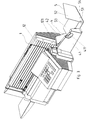
- Fig. 1
- Eine perspektivische Ansicht einer Frankiermaschine mit einer Anordnung zur Briefablage von vorn rechts gemäß DE 197 05 089 C1,
- Fig. 2
- Details zu Fig. 1 in Explosivdarstellung,
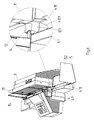
- Fig. 3
- eine perspektivische Ansicht einer Frankiermaschine mit einer Anordnung zur Briefablage von vorn rechts gemäß DE 197 42 893 A1,
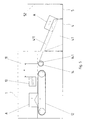
- Fig. 4
- eine Ansicht zur Lösung gemäß Fig. 3 von hinten rechts,
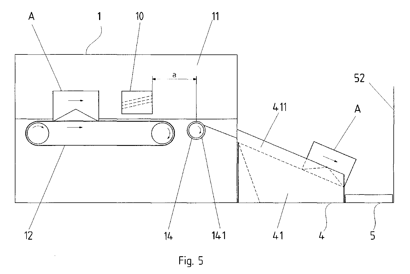
- Fig. 5
- ein Prinzipbild der erfindungsgemäßen Lösung mit auf der Kante stehenden Brieftransport,
- Fig. 6
- eine Ansicht zur Lösung gemäß Fig. 3 mit der erfindungsgemäßen Vorrichtung gemäß Fig.5 und einem Detail dazu,
- Fig. 7
- ein Prinzipbild der erfindungsgemäßen Lösung mit waagerechtem Brieftransport,
- Fig. 8
- eine perspektivische Ansicht zur Lösung gemäß Fig. 7.
Show it:
- Fig. 1
- A perspective view of a franking machine with an arrangement for depositing letters from the front right according to DE 197 05 089 C1,
- Fig. 2
- 1 in an exploded view,
- Fig. 3
- 2 shows a perspective view of a franking machine with an arrangement for depositing letters from the front right according to DE 197 42 893 A1,
- Fig. 4
- 3 from the rear right,
- Fig. 5
- 2 shows a schematic diagram of the solution according to the invention with letter transport standing on the edge,
- Fig. 6
- 3 with the device according to the invention according to FIG. 5 and a detail thereof,
- Fig. 7
- 2 shows a schematic diagram of the solution according to the invention with horizontal letter transport,
- Fig. 8
- 7 shows a perspective view of the solution according to FIG. 7.
Zur Vereinfachung und zum leichteren Verständnis ist die Darstellung schematisiert ausgeführt.The illustration is for simplification and easier understanding carried out schematically.
Gemäß Fig. 5 ist sind in einer Frankiermaschine 1 ein kontinuierlich
umlaufendes Transportband 12 für den Transport der Briefe A und in
Transportrichtung unmittelbar nach dem Transportband 12 eine angetriebene
Transportrolle 14 vorgesehen. Die Briefe A liegen während
des Durchlaufs durch die Frankiermaschine 1 an einer Führungsplatte
11 an und werden mittels eines Tintendruckkopfes 10 bedruckt, der bei
Druckbetrieb immobil ist. Der Tintendruckkopf 10 hat zur Transportrolle
14 einen orthogonalen Abstand a, der größer ist als der längste zu
erwartende Abdruck. Damit ist abgesichert, daß die Umfangsgeschwindigkeit
des Transportbandes 12, die mit der Schreibgeschwindigkeit
des Tintendruckkopfes 10 abgestimmt ist, durch die Transportrolle 14
nicht beeinflußt wird. Die Umfangsgeschwindigkeit der Transportrolle
14 ist größer eingestellt, als die des Tranportbandes 12, wodurch eine
Beschleunigung des austretenden Briefes A erreicht wird. Zur Unterstützung
des Effekts ist die Transportrolle 14 mit einem Belag 141
versehen, der einen entsprechend großen Reibwert hat. Als Material
kommt vorzugsweise ein geeigneter Polyuretan in Frage.
Die Gleitfläche 121 für die Briefunterkante in der Frankiermaschine 1
nach der Transportrolle 14 liegt etwas niedriger als der oberste Teil der
Transportrolle 14 und ist abschüssig gestaltet. Beim Überqueren der
Transportrolle 14 kippt der Brief A demzufolge auf die Gleitfläche 121
ab, wird bis zu seinem Ende noch durch die Transportrolle 14 beschleunigt
und gelangt beim Verlassen der Frankiermaschine 1 - immer
noch auf der Kante stehend - in die abschüssige Rinne 411. Die Rinne
411 ist in die Vorderwand 41 eines winkelförmigen Einsatzes 4 eingeformt,
der einerseits an die Frankiermaschine 1 angedockt und andererseits
mit einem Ablagekasten 5 verbunden ist. Die in Transportrichtung
hinten liegende Seitenwand 52 ist orthogonal zu ersterer
angeordnet und als federnde Prallwand ausgeführt.
In Fig. 6 ist eine konstruktive Ausführung der erfindungsgemäßen Lösung
nach Fig. 5 in Verbindung mit Fig. 3 und 4 dargestellt. In der
Frankier- und Adressiermaschine 1 ist gegenüber der Führungsplatte
11 eine Plexiglasscheibe 15 mit Abstand angeordnet. Der Boden des
so vorhandenen Schachtes für die Briefführung wird durch das Transportband
12, die Transportrolle 14 und die abschüssige Gleitfläche 121
gebildet. Der Ablagekasten 5 ist in dem winkelförmigen Einsatz 4 verstellbar
geführt. Entsprechend dem größten zur Verarbeitung kommenden
Briefformat wird der Ablagekasten 5 herausgezogen. Da die Briefe
A durch die nach hinten geneigte Führungsplatte 11 lagemäßig vororientiert
sind, kippen diese nach Aufprall auf die rechte Seitenwand 52
über die hintere Oberkante der Rinne 411 nach hinten in den Ablagekasten
5 ab. Die Steigung und Form der Gleitfläche 121 und der Anfangsbereich
4111 der Rinne 411 sind aneinander angepaßt.5, a continuously rotating
The sliding
6 shows a constructive embodiment of the solution according to the invention according to FIG. 5 in conjunction with FIGS. 3 and 4. In the franking and addressing
Bei Anschluß der Ablagevorrichtung gemäß Fig. 1 und 2 an die erfindungsgemäß
ausgestattete Frankiermaschine 1 sind die Verhältnisse
im wesentlichen analog. Auf Grund der schwenkbaren Wippe 21 im
Einsatz 2 fallen hier jedoch die Briefe nach vorn in den Ablagekasten 3.When connecting the storage device according to FIGS. 1 and 2 to the invention
equipped
Auch in Fig. 7 sind in einer Frankiermaschine 1 ein kontinuierlich umlaufendes
Transportband 12 für den Transport der Briefe A und in
Transportrichtung unmittelbar nach dem Transportband 12 eine angetriebene
Transportrolle 14 vorgesehen. Die Briefe A liegen während
des Durchlaufs durch die Frankiermaschine 1 waagerecht auf dem
Transportband 12 und werden mittels eines oberhalb desselben angeordneten
Tintendruckkopfes 10 bedruckt, der bei Druckbetrieb immobil
ist. Der Tintendruckkopf 10 hat zur Transportrolle 14 einen orthogonalen
Abstand a, der größer ist als der längste zu erwartende Abdruck.
Damit ist abgesichert, daß die Umfangsgeschwindigkeit des Transportbandes
12, die mit der Schreibgeschwindigkeit des Tintendruckkopfes
10 abgestimmt ist, durch die Transportrolle 14 nicht beeinflußt wird. Die
Umfangsgeschwindigkeit der Transportrolle 14 ist auch hier größer eingestellt,
als die des Tranportbandes 12, wodurch eine Beschleunigung
des austretenden Briefes A erreicht wird.
Die Gleitfläche für den Brief A in der Frankiermaschine 1 nach der
Transportrolle 14 liegt etwas niedriger als der oberste Teil der Transportrolle
14 und ist abschüssig gestaltet. Beim Überqueren der
Transportrolle 14 kippt der Brief A demzufolge auf die Gleitfläche ab,
wird bis zu seinem Ende noch durch die Transportrolle 14 beschleunigt
und gelangt beim Verlassen der Frankiermaschine 1 in den Ablagekasten
5. Die in Transportrichtung hinten liegende Seitenwand 52 ist
orthogonal zu ersterer angeordnet und als federnde Prallwand ausgeführt.
Der Brief A gleitet mit seiner Vorderkante auf dem Boden 53
des Ablagekastens 5 oder auf dem vorhergehenden Brief A entlang, bis
diese auf die Seitenwand 52 trifft. Die Hinterkante des Briefes A gleitet
an der vorn liegenden, schräg verlaufenden linken Seitenwand 55 des
Ablagekastens 5 hinab, siehe auch Fig. 8. Also in FIG. 7, a continuously rotating
The sliding surface for the letter A in the
- 11
- FrankiermaschineFranking machine
- 1010th
- berührungslose Druckeinrichtung, Tintendruckkopfnon-contact printing device, ink printhead
- 1111
-
Führungsplatte der Frankiermaschine 1Franking
machine guide plate 1 - 1212th
-
TransDortmittel bzw. Transportband der Frankiermaschine 1TransDort means or conveyor belt of the
franking machine 1 - 121121
-
Gleitfläche für die Briefunterkante in der Frankiermahine 1Sliding surface for the lower edge of the letter in
franking machine 1 - 1313
-
rechte Seitenwand der Frankiermaschine 1right side wall of the
franking machine 1 - 131131
-
Schlüssellöcher in der Seitenwand 13Keyholes in the
side wall 13 - 1414
-
Transportrolle in der Frankiermaschine 1Transport roller in the
franking machine 1 - 141141
-
Belag der Transportrolle 14Covering of the
transport roller 14
- 22nd
- Einsatz mit WippeUse with a seesaw
- 2020th
-
Vorderkante des Einsatzes 2Front edge of the
insert 2 - 2121
-
schwenkbare Wippe im Einsatz 2swiveling rocker in
use 2 - 2222
-
abfallende Rinne im Einsatz 2sloping channel in
use 2
- 33rd
- AblagekastenStorage box
- 3131
-
Boden des Ablagekastens 3Bottom of the
storage box 3 - 3232
-
linke Seitenwand des Ablagekastens 3left side wall of the
storage box 3 - 3333
-
Rückwand des Ablagekastens 3Rear wall of the
storage box 3 - 331331
-
Ausnehmung in der Rückwand 33Recess in the
rear wall 33
- 44th
- Einsatz winkelförmigAngled insert
- 4141
-
Vorderwand des Einsatzes 4Front wall of the
insert 4 - 411411
-
Rinne, in die Vorderwand 41 eingeformtChannel, molded into the
front wall 41 - 41114111
-
Anfangsbereich der Rinne 411Initial area of
channel 411
- 55
- Ablagekasten als WinkelteilStorage box as an angled part
- 5151
-
Vorderwand des Ablagekastens 5Front wall of the
storage box 5 - 5252
-
rechte Seitenwand des Ablagekastens 5right side wall of the
storage box 5 - 5353
-
Boden des Ablagekastens 5Bottom of the
storage box 5 - 5454
- Spaltgap
- 5555
- linke Seitenwand des Ablagekastensleft side wall of the storage box
- AA
- Postgut, BriefPostage, letter
- aa
-
orthogonaler Abstand zwischen Tintendruckkopf 10 und
Transportrolle 14orthogonal distance between
ink print head 10 andTransport roller 14
Claims (7)
dadurch gekennzeichnet,
characterized by
daß die Neigung und Form des Gleitbereiches (121) für die Briefunterkante in der Frankier- und/oder Adressiermaschine (1) und die Neigung und Form der Rinne (22 beziehungsweise 411) aneinander angepaßt sind.Device according to claims 1 and 4, characterized in that
that the inclination and shape of the sliding area (121) for the lower edge of the letter in the franking and / or addressing machine (1) and the inclination and shape of the channel (22 or 411) are matched to one another.
Applications Claiming Priority (2)
| Application Number | Priority Date | Filing Date | Title |
|---|---|---|---|
| DE19840917 | 1998-09-08 | ||
| DE19840917A DE19840917C1 (en) | 1998-09-08 | 1998-09-08 | Passing postal items, e.g. letters and cards, to storage arrangement, enabling stacked storage of mixed post |
Publications (3)
| Publication Number | Publication Date |
|---|---|
| EP0985619A2 true EP0985619A2 (en) | 2000-03-15 |
| EP0985619A3 EP0985619A3 (en) | 2000-12-27 |
| EP0985619B1 EP0985619B1 (en) | 2004-02-18 |
Family
ID=7880177
Family Applications (1)
| Application Number | Title | Priority Date | Filing Date |
|---|---|---|---|
| EP99250272A Expired - Lifetime EP0985619B1 (en) | 1998-09-08 | 1999-08-13 | Device for transferring postal items to a storage device |
Country Status (3)
| Country | Link |
|---|---|
| US (1) | US6390702B1 (en) |
| EP (1) | EP0985619B1 (en) |
| DE (2) | DE19840917C1 (en) |
Cited By (1)
| Publication number | Priority date | Publication date | Assignee | Title |
|---|---|---|---|---|
| US9062636B2 (en) | 2009-11-18 | 2015-06-23 | Mitsubishi Electric Corporation | Drop-in type of exhaust gas recirculation valve, and system for attaching same |
Families Citing this family (7)
| Publication number | Priority date | Publication date | Assignee | Title |
|---|---|---|---|---|
| DE19900687B4 (en) | 1999-01-05 | 2005-09-15 | Francotyp-Postalia Ag & Co. Kg | Arrangement for storing recording media |
| FR2820081B1 (en) * | 2001-01-26 | 2003-04-25 | Neopost Ind | TRANSFER MODULE |
| US7828286B2 (en) * | 2005-11-10 | 2010-11-09 | Xerox Corporation | Automatic document scanner with upright visible document images |
| EP2361864B1 (en) * | 2010-02-23 | 2013-11-20 | Neopost Technologies | Device for storing mail items |
| CN105346271B (en) * | 2015-10-21 | 2018-03-13 | 深圳市红源资产管理有限公司 | Printout conveyer and medical self-service printer |
| DE202016100099U1 (en) | 2016-01-12 | 2016-02-01 | Citec Gmbh | Storage device for flat goods |
| USD974461S1 (en) * | 2019-03-19 | 2023-01-03 | Opex Corporation | Envelope opener |
Family Cites Families (15)
| Publication number | Priority date | Publication date | Assignee | Title |
|---|---|---|---|---|
| DE2704823A1 (en) * | 1977-02-05 | 1978-08-10 | Volkswagenwerk Ag | Sheet transporter mechanism from copying machine - has fingers with friction surfaces on transverse shaft below discharge slot |
| FR2387892A1 (en) * | 1977-04-18 | 1978-11-17 | Roux Jacques | DEVICE FOR STORING FLAT OBJECTS |
| US4974828A (en) * | 1986-08-20 | 1990-12-04 | Canon Kabushiki Kaisha | Sheet stacking apparatus |
| CA2062602C (en) * | 1991-03-12 | 1995-02-14 | Peter Kern | Enveloping device |
| US5295674A (en) * | 1993-05-14 | 1994-03-22 | Xerox Corporation | High capacity envelope stacker apparatus |
| FR2712416A1 (en) * | 1993-11-10 | 1995-05-19 | Neopost Ind | Envelope feeder incorporating a scale. |
| US5470182A (en) * | 1994-02-04 | 1995-11-28 | Omation Corporation | Envelope opening machine |
| GB9416349D0 (en) * | 1994-08-12 | 1994-10-05 | Neopost Ltd | Mailing system |
| GB9423649D0 (en) * | 1994-11-23 | 1995-01-11 | Printed Forms Equip | Envelope invertor |
| DE19645303C1 (en) | 1996-01-31 | 1997-12-11 | Francotyp Postalia Gmbh | Device for printing a print carrier standing on an edge |
| DE19605014C1 (en) * | 1996-01-31 | 1997-03-13 | Francotyp Postalia Gmbh | Printing device for postal franking or addressing machine |
| DE19605015C1 (en) * | 1996-01-31 | 1997-03-06 | Francotyp Postalia Gmbh | Device for printing on print carrier standing on edge e.g. letter in franking or addressing machine |
| DE19705089C1 (en) * | 1997-02-01 | 1998-03-26 | Francotyp Postalia Gmbh | Record carrier storage arrangement for letters in postage and addressing machine |
| DE19742893A1 (en) * | 1997-09-24 | 1999-04-01 | Francotyp Postalia Gmbh | Arrangement for storing record carriers |
| DE19900687B4 (en) * | 1999-01-05 | 2005-09-15 | Francotyp-Postalia Ag & Co. Kg | Arrangement for storing recording media |
-
1998
- 1998-09-08 DE DE19840917A patent/DE19840917C1/en not_active Expired - Fee Related
-
1999
- 1999-08-13 EP EP99250272A patent/EP0985619B1/en not_active Expired - Lifetime
- 1999-08-13 DE DE59908563T patent/DE59908563D1/en not_active Expired - Lifetime
- 1999-09-08 US US09/391,718 patent/US6390702B1/en not_active Expired - Fee Related
Cited By (1)
| Publication number | Priority date | Publication date | Assignee | Title |
|---|---|---|---|---|
| US9062636B2 (en) | 2009-11-18 | 2015-06-23 | Mitsubishi Electric Corporation | Drop-in type of exhaust gas recirculation valve, and system for attaching same |
Also Published As
| Publication number | Publication date |
|---|---|
| DE59908563D1 (en) | 2004-03-25 |
| EP0985619B1 (en) | 2004-02-18 |
| EP0985619A3 (en) | 2000-12-27 |
| DE19840917C1 (en) | 2000-01-13 |
| US6390702B1 (en) | 2002-05-21 |
Similar Documents
| Publication | Publication Date | Title |
|---|---|---|
| DE19548492C2 (en) | Print media transport device for transporting sheets of print media from a print media tray to a print media path of a separate printer | |
| DE68915725T2 (en) | Stack stop for the feed device of a mail handling machine. | |
| DE8807146U1 (en) | Device for transporting bottles | |
| DE2711173B2 (en) | Device on a writing or printing office machine for loading the same with sheets | |
| DE69004818T2 (en) | Device for the upright stacking of flat objects from a belt into a container or the like or onto a fixed or movable stacking system. | |
| DE2757849A1 (en) | DEVICE FOR COLLECTING AND STACKING PHOTOGRAPHIC PAPER IMAGES | |
| DE4042358C2 (en) | Sorting device for storing sheet-like record carriers | |
| DE3873075T2 (en) | DEVICE FOR AUTOMATICALLY DISPENSING OBJECTS. | |
| DE2945386C2 (en) | Device for printing mail items with coded or uncoded postal codes | |
| DE19535330B4 (en) | sorter | |
| DE3008897C2 (en) | Sorter for single sheets of paper fed from a copier or printer | |
| EP0985619B1 (en) | Device for transferring postal items to a storage device | |
| DE2838896C2 (en) | ||
| DE3709726A1 (en) | LEAF EJECTOR | |
| WO2002010046A1 (en) | Device for stacking flat objects in containers that are open on one side | |
| DE69710016T2 (en) | Device for collecting and orienting sheets | |
| DE69915699T2 (en) | DEVICE FOR TRANSPORTING FLAT OBJECTS BETWEEN PROCESSING EQUIPMENT | |
| DE19836235A1 (en) | Device for separating print media | |
| DE2344813A1 (en) | DEVICE FOR FILING SHEETS | |
| EP0961236B1 (en) | Apparatus for printing mailpieces | |
| DE2425736C3 (en) | Apparatus for successively feeding recording sheets | |
| EP3192757B1 (en) | Stacker device for flat goods | |
| DE1902822A1 (en) | Sheet sorter | |
| DE1636290A1 (en) | Collective channel for gathering machines | |
| DE3031869A1 (en) | Sheet feed mechanism for typewriter or data processor - has stationary sheet support surface at writer, with transport rollers below |
Legal Events
| Date | Code | Title | Description |
|---|---|---|---|
| PUAI | Public reference made under article 153(3) epc to a published international application that has entered the european phase |
Free format text: ORIGINAL CODE: 0009012 |
|
| AK | Designated contracting states |
Kind code of ref document: A2 Designated state(s): CH DE FR GB IT LI |
|
| AX | Request for extension of the european patent |
Free format text: AL;LT;LV;MK;RO;SI |
|
| PUAL | Search report despatched |
Free format text: ORIGINAL CODE: 0009013 |
|
| AK | Designated contracting states |
Kind code of ref document: A3 Designated state(s): AT BE CH CY DE DK ES FI FR GB GR IE IT LI LU MC NL PT SE |
|
| AX | Request for extension of the european patent |
Free format text: AL;LT;LV;MK;RO;SI |
|
| RIC1 | Information provided on ipc code assigned before grant |
Free format text: 7B 65H 29/22 A, 7G 07B 17/00 B, 7B 41J 13/10 B |
|
| 17P | Request for examination filed |
Effective date: 20010417 |
|
| AKX | Designation fees paid |
Free format text: CH DE FR GB IT LI |
|
| RAP1 | Party data changed (applicant data changed or rights of an application transferred) |
Owner name: FRANCOTYP-POSTALIA AG & CO. KG |
|
| 17Q | First examination report despatched |
Effective date: 20020911 |
|
| GRAP | Despatch of communication of intention to grant a patent |
Free format text: ORIGINAL CODE: EPIDOSNIGR1 |
|
| GRAS | Grant fee paid |
Free format text: ORIGINAL CODE: EPIDOSNIGR3 |
|
| GRAA | (expected) grant |
Free format text: ORIGINAL CODE: 0009210 |
|
| AK | Designated contracting states |
Kind code of ref document: B1 Designated state(s): CH DE FR GB IT LI |
|
| REG | Reference to a national code |
Ref country code: GB Ref legal event code: FG4D Free format text: NOT ENGLISH |
|
| REG | Reference to a national code |
Ref country code: CH Ref legal event code: NV Representative=s name: ROTTMANN, ZIMMERMANN + PARTNER AG Ref country code: CH Ref legal event code: EP |
|
| REF | Corresponds to: |
Ref document number: 59908563 Country of ref document: DE Date of ref document: 20040325 Kind code of ref document: P |
|
| GBT | Gb: translation of ep patent filed (gb section 77(6)(a)/1977) |
Effective date: 20040614 |
|
| ET | Fr: translation filed | ||
| PLBE | No opposition filed within time limit |
Free format text: ORIGINAL CODE: 0009261 |
|
| STAA | Information on the status of an ep patent application or granted ep patent |
Free format text: STATUS: NO OPPOSITION FILED WITHIN TIME LIMIT |
|
| 26N | No opposition filed |
Effective date: 20041119 |
|
| REG | Reference to a national code |
Ref country code: CH Ref legal event code: PFA Owner name: FRANCOTYP-POSTALIA AG & CO. KG Free format text: FRANCOTYP-POSTALIA AG & CO. KG#TRIFTWEG 21-26#16547 BIRKENWERDER (DE) -TRANSFER TO- FRANCOTYP-POSTALIA AG & CO. KG#TRIFTWEG 21-26#16547 BIRKENWERDER (DE) |
|
| PGFP | Annual fee paid to national office [announced via postgrant information from national office to epo] |
Ref country code: CH Payment date: 20110824 Year of fee payment: 13 |
|
| PGFP | Annual fee paid to national office [announced via postgrant information from national office to epo] |
Ref country code: GB Payment date: 20120821 Year of fee payment: 14 |
|
| PGFP | Annual fee paid to national office [announced via postgrant information from national office to epo] |
Ref country code: FR Payment date: 20120906 Year of fee payment: 14 Ref country code: IT Payment date: 20120821 Year of fee payment: 14 Ref country code: DE Payment date: 20120606 Year of fee payment: 14 |
|
| REG | Reference to a national code |
Ref country code: CH Ref legal event code: PL |
|
| GBPC | Gb: european patent ceased through non-payment of renewal fee |
Effective date: 20130813 |
|
| PG25 | Lapsed in a contracting state [announced via postgrant information from national office to epo] |
Ref country code: DE Free format text: LAPSE BECAUSE OF NON-PAYMENT OF DUE FEES Effective date: 20140301 Ref country code: CH Free format text: LAPSE BECAUSE OF NON-PAYMENT OF DUE FEES Effective date: 20130831 Ref country code: LI Free format text: LAPSE BECAUSE OF NON-PAYMENT OF DUE FEES Effective date: 20130831 |
|
| REG | Reference to a national code |
Ref country code: FR Ref legal event code: ST Effective date: 20140430 |
|
| REG | Reference to a national code |
Ref country code: DE Ref legal event code: R119 Ref document number: 59908563 Country of ref document: DE Effective date: 20140301 |
|
| PG25 | Lapsed in a contracting state [announced via postgrant information from national office to epo] |
Ref country code: IT Free format text: LAPSE BECAUSE OF NON-PAYMENT OF DUE FEES Effective date: 20130813 |
|
| PG25 | Lapsed in a contracting state [announced via postgrant information from national office to epo] |
Ref country code: GB Free format text: LAPSE BECAUSE OF NON-PAYMENT OF DUE FEES Effective date: 20130813 |
|
| PG25 | Lapsed in a contracting state [announced via postgrant information from national office to epo] |
Ref country code: FR Free format text: LAPSE BECAUSE OF NON-PAYMENT OF DUE FEES Effective date: 20130902 |