EP0985634B1 - Kraftstoffdampfüberwachungsvorrichtung in Tankanlagen - Google Patents
Kraftstoffdampfüberwachungsvorrichtung in Tankanlagen Download PDFInfo
- Publication number
- EP0985634B1 EP0985634B1 EP99307139A EP99307139A EP0985634B1 EP 0985634 B1 EP0985634 B1 EP 0985634B1 EP 99307139 A EP99307139 A EP 99307139A EP 99307139 A EP99307139 A EP 99307139A EP 0985634 B1 EP0985634 B1 EP 0985634B1
- Authority
- EP
- European Patent Office
- Prior art keywords
- vapour
- tank
- controller
- vapour recovery
- vehicle
- Prior art date
- Legal status (The legal status is an assumption and is not a legal conclusion. Google has not performed a legal analysis and makes no representation as to the accuracy of the status listed.)
- Expired - Lifetime
Links
- 238000011084 recovery Methods 0.000 claims description 195
- 239000000446 fuel Substances 0.000 claims description 82
- 229930195733 hydrocarbon Natural products 0.000 claims description 66
- 150000002430 hydrocarbons Chemical class 0.000 claims description 66
- 239000004215 Carbon black (E152) Substances 0.000 claims description 57
- 239000002828 fuel tank Substances 0.000 claims description 24
- 239000007788 liquid Substances 0.000 claims description 21
- 238000012544 monitoring process Methods 0.000 claims description 14
- 238000004891 communication Methods 0.000 claims description 11
- 238000013528 artificial neural network Methods 0.000 claims description 8
- 239000003570 air Substances 0.000 description 33
- 238000000034 method Methods 0.000 description 30
- 230000008569 process Effects 0.000 description 24
- 230000006870 function Effects 0.000 description 19
- 238000007726 management method Methods 0.000 description 11
- 230000001276 controlling effect Effects 0.000 description 10
- 239000000835 fiber Substances 0.000 description 9
- 230000000694 effects Effects 0.000 description 8
- 239000003502 gasoline Substances 0.000 description 7
- 229920006395 saturated elastomer Polymers 0.000 description 7
- 239000012080 ambient air Substances 0.000 description 6
- 238000013459 approach Methods 0.000 description 6
- 238000004422 calculation algorithm Methods 0.000 description 6
- 239000000945 filler Substances 0.000 description 6
- 239000000203 mixture Substances 0.000 description 6
- 230000029058 respiratory gaseous exchange Effects 0.000 description 6
- 238000001514 detection method Methods 0.000 description 5
- 238000010586 diagram Methods 0.000 description 5
- 230000037406 food intake Effects 0.000 description 5
- 230000009471 action Effects 0.000 description 4
- QVGXLLKOCUKJST-UHFFFAOYSA-N atomic oxygen Chemical compound [O] QVGXLLKOCUKJST-UHFFFAOYSA-N 0.000 description 4
- 230000001419 dependent effect Effects 0.000 description 4
- 229910052760 oxygen Inorganic materials 0.000 description 4
- 239000001301 oxygen Substances 0.000 description 4
- 238000013022 venting Methods 0.000 description 4
- 230000008859 change Effects 0.000 description 3
- 238000013461 design Methods 0.000 description 3
- 238000012423 maintenance Methods 0.000 description 3
- 230000007257 malfunction Effects 0.000 description 3
- 230000007246 mechanism Effects 0.000 description 3
- 238000007689 inspection Methods 0.000 description 2
- 238000005259 measurement Methods 0.000 description 2
- 230000000737 periodic effect Effects 0.000 description 2
- 230000001105 regulatory effect Effects 0.000 description 2
- 238000009420 retrofitting Methods 0.000 description 2
- 239000007787 solid Substances 0.000 description 2
- XLYOFNOQVPJJNP-UHFFFAOYSA-N water Substances O XLYOFNOQVPJJNP-UHFFFAOYSA-N 0.000 description 2
- 238000010521 absorption reaction Methods 0.000 description 1
- 238000009530 blood pressure measurement Methods 0.000 description 1
- 210000004556 brain Anatomy 0.000 description 1
- 238000004364 calculation method Methods 0.000 description 1
- 239000011248 coating agent Substances 0.000 description 1
- 238000000576 coating method Methods 0.000 description 1
- 238000004590 computer program Methods 0.000 description 1
- 230000007613 environmental effect Effects 0.000 description 1
- 238000002329 infrared spectrum Methods 0.000 description 1
- 238000009434 installation Methods 0.000 description 1
- 230000010354 integration Effects 0.000 description 1
- 230000001678 irradiating effect Effects 0.000 description 1
- 239000000463 material Substances 0.000 description 1
- 230000000116 mitigating effect Effects 0.000 description 1
- 238000012986 modification Methods 0.000 description 1
- 230000004048 modification Effects 0.000 description 1
- 238000012806 monitoring device Methods 0.000 description 1
- 230000003287 optical effect Effects 0.000 description 1
- 230000002093 peripheral effect Effects 0.000 description 1
- 230000002028 premature Effects 0.000 description 1
- 238000012545 processing Methods 0.000 description 1
- 230000004044 response Effects 0.000 description 1
- 230000000717 retained effect Effects 0.000 description 1
- 239000000523 sample Substances 0.000 description 1
- 238000007789 sealing Methods 0.000 description 1
- 230000035945 sensitivity Effects 0.000 description 1
- 238000012360 testing method Methods 0.000 description 1
- 229930195735 unsaturated hydrocarbon Natural products 0.000 description 1
- 239000012855 volatile organic compound Substances 0.000 description 1
Images





Classifications
-
- B—PERFORMING OPERATIONS; TRANSPORTING
- B67—OPENING, CLOSING OR CLEANING BOTTLES, JARS OR SIMILAR CONTAINERS; LIQUID HANDLING
- B67D—DISPENSING, DELIVERING OR TRANSFERRING LIQUIDS, NOT OTHERWISE PROVIDED FOR
- B67D7/00—Apparatus or devices for transferring liquids from bulk storage containers or reservoirs into vehicles or into portable containers, e.g. for retail sale purposes
- B67D7/04—Apparatus or devices for transferring liquids from bulk storage containers or reservoirs into vehicles or into portable containers, e.g. for retail sale purposes for transferring fuels, lubricants or mixed fuels and lubricants
- B67D7/0476—Vapour recovery systems
- B67D7/0478—Vapour recovery systems constructional features or components
- B67D7/048—Vapour flow control means, e.g. valves, pumps
- B67D7/0482—Vapour flow control means, e.g. valves, pumps using pumps driven at different flow rates
- B67D7/0486—Pumps driven in response to electric signals indicative of pressure, temperature or liquid flow
-
- B—PERFORMING OPERATIONS; TRANSPORTING
- B67—OPENING, CLOSING OR CLEANING BOTTLES, JARS OR SIMILAR CONTAINERS; LIQUID HANDLING
- B67D—DISPENSING, DELIVERING OR TRANSFERRING LIQUIDS, NOT OTHERWISE PROVIDED FOR
- B67D7/00—Apparatus or devices for transferring liquids from bulk storage containers or reservoirs into vehicles or into portable containers, e.g. for retail sale purposes
- B67D7/04—Apparatus or devices for transferring liquids from bulk storage containers or reservoirs into vehicles or into portable containers, e.g. for retail sale purposes for transferring fuels, lubricants or mixed fuels and lubricants
- B67D7/0476—Vapour recovery systems
-
- B—PERFORMING OPERATIONS; TRANSPORTING
- B67—OPENING, CLOSING OR CLEANING BOTTLES, JARS OR SIMILAR CONTAINERS; LIQUID HANDLING
- B67D—DISPENSING, DELIVERING OR TRANSFERRING LIQUIDS, NOT OTHERWISE PROVIDED FOR
- B67D7/00—Apparatus or devices for transferring liquids from bulk storage containers or reservoirs into vehicles or into portable containers, e.g. for retail sale purposes
- B67D7/04—Apparatus or devices for transferring liquids from bulk storage containers or reservoirs into vehicles or into portable containers, e.g. for retail sale purposes for transferring fuels, lubricants or mixed fuels and lubricants
- B67D7/0476—Vapour recovery systems
- B67D7/0496—Performance test devices therefor
Definitions
- the present invention relates to a service station vapour recovery management system and more particularly to a controller configured to receive information from various devices in the fuelling environment and make logical decisions based on the received information to maximize the vapour recovery efficiency of the service station.
- Vapour Vac® Distributed, assist vapour recovery systems, such as Marconi Commerce Systems Inc.'s Vapour Vac® system are used to recover hydrocarbon vapours that normally escape to the atmosphere from vehicle tanks during refuelling and return these vapours to the underground storage tank. Most of these assist vapour recovery systems have a vapour recovery rate that is a function of the fuel delivery rate of the dispenser with which they are associated.
- the recovery efficiency will vary considerably with variations in vehicle fuel neck designs.
- the objective in obtaining regulatory certification is to tune an assist systems recovery algorithm to achieve 95% efficiency when measured over a number of vehicles in the certification test.
- Another major variable that will have a dramatic effect on overall site efficiency is vehicles equipped with onboard vapour recovery systems (ORVR).
- ORVR onboard vapour recovery systems
- ORVR onboard vapour recovery systems
- vapour recovery vapour/liquid (V/L) ratio or curve for each model vehicle tank and filler neck design, among other variables, and store them in memory in the vapour recovery system. It is also possible to add a smart card or transponder-type device to the vehicle to communicate with the dispenser and provide the dispenser with information necessary to select an appropriate vapour recovery algorithm for the vehicle.
- V/L vapour/liquid
- a smart card or transponder-type device to the vehicle to communicate with the dispenser and provide the dispenser with information necessary to select an appropriate vapour recovery algorithm for the vehicle.
- each dispenser operates independently of each other without accounting for its effect on the other, each being concerned with achieving a vapour recovery efficiency level for that particular dispenser.
- the present invention provides a service station vapour management system including, a plurality of vapour handling subsystems and a controller in communication with and arranged to monitor operation of the plurality of vapour handling subsystems and to control overall hydrocarbon emission from the service station by determining an overall service station ratio of vapour recovered to liquid dispensed (V/L ratio) and control subsystem operation to maintain the overall V/L ratio within predetermined limits.
- a service station vapour management system including, a plurality of vapour handling subsystems and a controller in communication with and arranged to monitor operation of the plurality of vapour handling subsystems and to control overall hydrocarbon emission from the service station by determining an overall service station ratio of vapour recovered to liquid dispensed (V/L ratio) and control subsystem operation to maintain the overall V/L ratio within predetermined limits.
- Employing the present invention provides a service station vapour management system that manages vapour handling subsystems to achieve a particular performance characteristic for an entire site.
- the controller may be arranged to control subsystem operation to maintain hydrocarbon vapour discharge within predetermined limits.
- the system may also include at least one ambient temperature sensor or at least one atmospheric pressure sensor for providing ambient temperature or atmospheric pressure information to the controller.
- This control system is in electronic communication with the controller.
- the invention may employ at least one fuel dispenser vapour recovery system, controlled by the controller, for collecting vapour generated during a vehicle fuelling operation and returning the vapour to an underground tank, the controller monitoring the operation of the system, and controlling the operation of the at least one vapour recovery system to control overall emissions of hydrocarbon vapours from the service station.
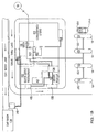
- an automobile 100 is shown being fuelled from a gasoline dispenser or pump 18.
- a spout 28 of nozzle 2 is shown inserted into a filler pipe 22 of a fuel tank 20 during the refuelling of the automobile 100.
- a fuel delivery hose 4 has an annular fuel delivery passageway 12 and a tubular vapour recovery passageway 8 for transferring fuel vapours expelled from the vehicle's fuel tank 20 to underground storage tank 5 during the fuelling of a vehicle that is not equipped with an onboard vapour recovery system.
- a vapour recovery pump 14 provides a vacuum in the vapour recovery passage 8 for removing fuel vapour during a refuelling operation.
- the underground tank 5 includes a vent 17 and a pressure-vacuum vent valve 19 for venting the underground tank 5 to atmosphere.
- the vent 17 and controllable vent valve 19 allow the underground tank 5 to breathe in order to substantially equalize the ambient and tank pressures as well as control hydrocarbon vapour levels to minimize breathing losses.
- the valve may be constructed to open and close at preset pressure and vacuum points. Typical set points are +76.2 mm (+3 inches) of water pressure and -203.2 mm (-8 inches) of water.
- Figure 1B depicts a typical fuelling and retail environment including a forecourt where the fuel dispensers 18 are located, a convenience or fuel station store 120, one or more quick-serve restaurants (QSR) 122, a car wash 124, and a backroom 126.
- the backroom 126 is generally the central control area for integrating or coordinating control of the fuel dispensers 18, convenience store 20, QSR 122, and car wash 124. In the present invention, it is preferable to incorporate any necessary control for the overall vapour recovery site management system in this central control area.
- This central control area will include a central control system 50 configured with the necessary hardware, software.
- the central control system 50 may include a number of individual controllers for various parts of the fuelling environment to provide overall system control integration.
- the central control system 50 will typically interface with the dispensers 18, store transaction terminal 130, and other ancillary components necessary. Additionally the dispensers 18 have interrogators 152, providing communications with transponders 164.
- the transponders are configured to transmit information indicative of the presence of ORVR equipment, and optionally, information aiding the dispensers vapour recovery system and optimizing vapour recovery. Such information may include the type of ORVR equipment, automobile fuel tank configuration, fuel tank internal ullage pressure, volume or vapour pressure or preferred vapour recovery functions for the particular make or model of the vehicle.
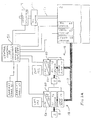
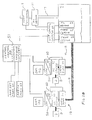
- the central control system 50 may be the central controller for the entire station or the dedicated vapour recovery management control system, with concentrating hardware to manage the input and output control corresponding to the various peripheral systems and components.
- the central control system 50 interfaces with one or more of the following systems or components: fuel dispensers 18, the underground storage tank 5, or ambient measurement devices.
- Each fuel dispenser includes a CPU 56 and necessary hardware or software for vapour recovery control of a vapour recovery pump 14.
- the dispenser includes the vapour recovery passage 8 and preferably a hydrocarbon sensor 32 associated with the vapour recovery passage 8 and/or an interrogator 152 configured to communicate with ORVR equipped vehicles.
- each fuel dispenser controls its own vapour recovery system under the direction of the CPU 56 and vapour recovery controller 60. The manner in which vapour recovery is controlled is based on the presence of ORVR equipment, V/L ratios and/or information from the central control system 50 relating to overall management of vapour recovery for the site.
- Information concerning the presence of an ORVR equipped vehicle may be received through RFID techniques using the interrogator 152, sensing hydrocarbon concentrations in the vapour recovery passage, sensing pressure changes in the vapour recovery passage, or any other known or future method for detecting ORVR equipment.
- the vapour recovery rates may be based on information received from the vehicle through the interrogator 152, control algorithms for general vapour recovery, specific vapour recovery control algorithms for a type of vehicle, fuel delivery rate, fuel tank initial volume at the beginning of the fuelling process and/or temperatures and pressures relating to the vapour recovery system or the ambient.
- the central control system 50 is provided access to ambient temperature data through an ambient temperature sensor 61 and ambient atmospheric pressure data through an ambient pressure transducer 63. Furthermore, the central control system has access to hydrocarbon concentration, pressure and temperature information relating to the underground storage tank 5 and its vent 17.
- hydrocarbon sensors 21, 65 may be placed in the vent 17 for the underground storage tank 5, respectively.
- the underground storage tank 5 may also include a temperature sensor 68 and a pressure sensor 67.
- the vent 17 is provided with a controllable vent valve 19 in order to variably control venting.
- the vent valve 19 will preferably derive a portion of its control from the central control system 50, either directly or indirectly through other control systems associated with the underground storage tank 5.
- vent control and sensor inputs may be directed to an underground storage tank control subsystem 69 which is in communication with the central control system 50.
- the central control system 50 will basically interact with the dispenser control systems and the underground storage tank control subsystem 69 in order to optimize site efficiency.
- the underground tank control system may be an ullage pressure control system is known in the art.
- the central control system 50 may be directly linked to various sensors or configured to receive information from the underground storage tank control system 69. Control signals or information directed to the underground storage tank may likewise be sent directly to any system, such as the vent control valve 19, directly or through the underground storage tank control system 69.
- ambient temperature and pressure may be read by the underground storage tank control system 69 or any one of the numerous dispensers in the forecourt.
- information may be received from three sources: 1) the fuel dispenser, 2) the underground storage tank, and 3) sensors or systems providing data on ambient conditions. Additional sources of information include the dispenser vapour recovery subsystem, the tank ullage control subsystem and a vehicle discrimination subsystem.
- the dispenser may provide information relating to vapour recovery performance and conditions for the individual dispenser, the presence or type of ORVR equipment on a vehicle being fuelled or vehicles having been fuelled, and, as noted above, ambient conditions.
- the vapour recovery information may include V/L ratios, operating efficiencies, and equipment conditions.
- the ORVR equipment information may be received using a radio frequency identification device (RFID) technique wherein information is directly communicated from the vehicle to the dispenser indicating the presence or absence of ORVR equipment, and optionally, providing vehicle configuration information or vapour recovery control functions to help optimize vapour recovery with respect to that particular vehicle.
- RFID radio frequency identification device
- the dispenser may detect the presence of ORVR equipment on a vehicle based on techniques including sensing hydrocarbon concentrations or pressure increases in the vapour return passage 8 that are indicative of the presence of ORVR equipment.
- the dispensers and underground storage tank control systems may be configured to collect historical information relating to any of the above parameters.
- the central control system 50 may periodically gather information and maintain historical records as desired to gather information helpful in monitoring and controlling site efficiencies.
- the underground tank vent may share control processes with the underground storage tank control system or may include its own control system for monitoring hydrocarbon concentrations, the ingress or egress of air and/or hydrocarbon vapours to and from the underground storage tank, and controlling venting.
- the processor would preferably communicate directly with the central control system 50 or concentrating hardware 51.
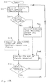
- the process starts at block 200 where various set points and control parameters are checked, determined or updated as desired (block 202).
- the information necessary for the particular management configuration is received from the various vapour handling systems and/or sensors providing selected information from that described immediately above (block 204).
- the information is analysed (block 206) and compared as with the set points and/or control parameters (block 208).
- the control system will then determine any necessary adjustments for the vapour handling subsystems, underground storage tank and/or underground storage tank vent to maintain or move toward a desired overall operational state (block 210). If any adjustments are necessary, the central control system 50 will provide the necessary control signals to affect adjustments to the vapour handling subsystems in the dispensers and/or underground storage tank, the underground storage tank and/or the underground storage tank vent (block 212).
- the central control system 50 treats the site as a whole by taking input from the several vapour handling subsystems and sensors to make logical decisions regarding the values of variable subsystem parameters to maximize the vapour recovery efficiency of the site.
- vapour handling subsystems includes individual fuel dispenser vapour recovery systems, vehicle discrimination systems to include vehicle interrogation systems and UST ullage pressure control systems and any other systems that transport, manage or are otherwise associated with hydrocarbon vapours generated during fuelling operations. To affect these changes that improve efficiency, this system provides input to the Stage II assist vapour recovery subsystems in the fuel dispensers in order to adjust their V/L ratios to improve efficiency in recovering vapours.
- the system may also make changes to the fuel storage tanks venting system to control the amount of ingress or ambient air of the amount of egress of an air/hydrocarbon, vapour mixture.
- any one or more of the following is preferably used: pressure transducers, hydrocarbon sensors, mass spectrometers 73, vapour flow meters 71, intelligent assist vapour recovery system controls, temperature sensors, and electronically controlled and operated storage tank vent valving.
- the central control system 50 receives underground fuel storage tank and ambient air temperatures and uses this information to adjust a baseline V/L value in the dispensers vapour recovery system. Independent of or in conjunction with this action, the central control system 50 may keep a record of a number of ORVR and non-ORVR vehicle refuelling operations and corresponding storage tank ullage pressures. From this data, the controller calculates the average site V/L, and determines changes in dispenser V/L values, either individually or by site, and may also define the amount of ingress or egress to allow at the storage tank vent.
- the controller used in the practice of the present invention may desirably use one or more trained artificial neural networks (ANN) or fuzzy logic devices to affect the control of the various vapour handling subsystems.
- ANN is a well-known tool for handling problems that involve many variables.
- a typical ANN is a computer program, modelled roughly after the human brain, that can learn to perform tasks and make decisions based on past experiences or examples.
- Computers so programmed learn by gathering and storing information from the computer user. When the computer receives new information, it uses its stored expertise to classify or recognize a new pattern in the information.
- the ANN may be trained to expect certain patterns of environmental conditions, i.e.
- the ANN may control the various vapour handling subsystems to maintain a particular overall site V/L ratio, to control total site hydrocarbon vapour emissions, or to control fugitive emissions from an underground tank. It will be readily appreciated that an ANN trained for a cold weather climate site may manage vapour handling subsystems much differently than that for a hot weather climate site.
- this system will track the fuelling of ORVR and non-ORVR equipped vehicles and use this information to adjust each dispensers vapour recovery system V/L ratio or curve for non-ORVR vehicles.
- the central site controller 50 can send commands to the individual dispenser to turn the vapour recovery system off or modify the V/L ratio.
- the system can increase V/L for non-ORVR vehicles if the underground storage tank pressure stays low most of the time. It can also decrease the V/L to the minimum certified level for non-ORVR vehicle refuelling if the underground storage tank pressure increases during a period of the day or night. This process will minimize the pressure differential between the underground storage tanks and atmosphere.
- the system may gradually decrease the V/L for non-ORVR vehicles to the minimum certified level during the hours prior to station close or the time when tank pressure starts to go up. This process prevents or minimizes fugitive emissions.
- the practice of the present invention includes the additional step of determining what type of seal mechanism is installed in the fill neck of an ORVR vehicle and using that information to make the decision whether or not to modify dispenser vapour recovery system operation. Under certain circumstances, no changes would be made to that operation.
- each dispenser may be configured to adjust and correct the V/L ratio after a predetermined number of ORVR vehicles have been refuelled.
- a preprogrammed family of algorithms or the ability to internally compute the algorithm necessary to make the appropriate adjustment may be provided.
- a central control system can monitor individual dispenser usage and adjust its respective V/L ratio to achieve the minimum necessary level of vapour recovery at the vehicle fill-neck in order to reduce storage tank pressure. The system can also adjust the V/L ratios in those dispensers that are used less by the customers to further manage underground storage tank pressure.
- each dispenser may end up having its own V/L ratio at any given time. A history of adjustments can be recorded and be available for inspection.
- the central control system 50 may print periodic reports concerning the vapour emission performance of a particular location.
- remote electronic access may be provided using dial up connections, satellite communications links or Internet links.
- Each of these communication methods could provide historical information on a periodic batch basis or, alternatively, provide the ability to monitor system performance in a real time fashion.
- a remote central monitoring station could be established for monitoring the operation of a number of sites. Data from these sites can be assembled and analysed to provide an area-wide assessment of vapour emission performance.
- the benefits of this approach include, but are not limited to, the ability to identify sites that require equipment maintenance, to monitor the population distribution of ORVR and non-ORVR vehicles, and to identify those locations/areas that are not in compliance with emissions limits. This data could be made available to regulatory authorities to meet compliance inspection requirements again using the electronic communications links discussed above.
- the provision of remote monitoring of site vapour emission performance makes remote adjustment of system performance possible. That is, responsive to the system performance data received at a remote location, a person or a controller remote from the location may transmit instructions to the onsite controller 50 to change system performance.
- This approach is an extension of the concept of coordinating the operation of the vapour handling subsystems at a particular location.
- the practice of the present invention includes coordinating the operation of a number of individual vapour emitting locations as part of a cohesive strategy for addressing vapour emissions for a particular geographic area.
- the system can also automatically record tank pressure or fugitive emission violations with the times and dates of such occurrences. Violations can be reported to maintenance personnel and allow the entire site to, in effect, provide a self compliance method of operation. Historical information concerning these violations can be used by regulators for enforcement efforts.
- a solenoid valve on the tank vent makes it possible for the system to check for leaks in the underground piping and the tank installation.
- the system may monitor tank pressure while the solenoid valve is closed and there is no refuelling activity at the site. Pressure changes may be monitored over time. If the pressure change during this time is greater than a predetermined value, the central site control system can send a request to maintenance personnel or the station manager to check for possible leakage or other system malfunctions. This feature can also by used as part of a self-compliance program.
- the system may have a leak detection program that closes the vent valve, increases the tank pressure to a predetermined level, stops all fuelling activities for a predetermined period of time and checks for a pressure drop.
- the tank vent may be equipped with a vapour flow meter 71 that measures the amount of egress and ingress from and into the underground storage tank.
- the vapour flow meter 71 may be directly coupled to the central control system 50 or the concentrating hardware 51.
- the flow meter 71 may be coupled directly to an underground storage tank control system, as disclosed in Figure 2B.
- standard dispenser vapour recovery systems include a similar flow meter in vapour return passage. The output of the dispenser vapour flow meters are generally provided directly to the dispensers control system.
- the vent may also be equipped with a thermocouple, or a hydrocarbon sensor configured as a mass spectrometer 73 to measure the concentration and/or the amount of harmful volatile organic compounds in the egress vapour from the tank and the amount of ambient air ingressed to the tank.
- the output of the vapour flow meter 71 can be recorded for emission calculations.
- the processor can be equipped with a thermocouple, vapour flow meter 71, hydrocarbon sensor and/or mass spectrometer 73 to monitor its efficiency and output into the atmosphere.
- the output of all measurement and monitoring devices is directly or indirectly fed to the central site controller 50. This controller is used to make the decisions on setting, affecting, and/or controlling vapour recovery and vapour recovery ratios throughout the system.
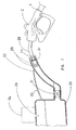
- the vehicle fuel tank 20 of an ORVR vehicle has an associated onboard vapour recovery system 24.
- These onboard vapour recovery systems 24 typically have a vapour recovery inlet 26 extending into the tank 20 (as shown) or the filler pipe 22 and communicating with the vapour recovery system 24.
- incoming fuel provides a seal in fill neck 22 to prevent vapours from within the tank 20 to escape. This sealing action is often referred to as a liquid seal.
- pressure within tank 20 increases and forces vapours into the vapour recovery system 24 through the vapour recovery inlet 26.
- Other ORVR systems may use a check valve 21 along the fill neck 22 to prevent further loss of vapours.
- the check valve 21 is normally closed and opens when a set amount of gasoline accumulates over the check valve within the fill neck 22.
- the spout 28 has numerous apertures 29.
- the apertures 29 provide an inlet for fuel vapours to enter the vapour recovery path 8 of fuel dispenser 18 from the vehicle's filler pipe 22.
- fuel vapours are forced out of the fuel tank 20 through the fill pipe 22.
- the fuel dispenser's vapour recovery system pulls fuel vapour through the vapour recovery apertures 29, along the vapour recovery path 8 and ultimately into the underground tank 5 (as shown in Figure 1).
- FIGS 4 and 5 depict partial and complete cross-sectional views of the fuel dispenser hose 4.
- a hydrocarbon sensor 32 is placed inside the vapour passage 8 to detect the presence or absence of hydrocarbons associated with fuel vapours. An absence of hydrocarbons in the vapour passage 8 indicates the presence of an onboard vapour recovery system in the vehicle being fuelled. If an onboard system is detected, the dispenser could either shut off the vapour pump 14 completely, or calculate and control the pump 14 to supply the amount of air to the storage tank needed to replenish the volume of liquid taken from the tank 5 and thus eliminate breathing losses.
- the hydrocarbon sensor 32 may be located anywhere along the vapour recovery passage 8, including within the vapour recovery pump 14, storage tank 5, dispenser 18, or hanging hardware. Certain applications will locate the hydrocarbon sensor 32 at either, or both, an inlet or outlet to the vapour recovery pump 14.
- the hydrocarbon sensor 32 is a fibre-optic sensor 44 capable of sensing an amount or concentration of hydrocarbons present in the vapour return passage 8 to detect the presence of an ORVR-equipped vehicle.
- the fibre-optic sensor 44 is shown in detail in Figure 6.
- the fibre-optic sensor 44 uses two fibre-optic light rails 46, a sense fibre 46a and a reference fibre 46b.
- the sense fibre 46a has a special coating and the reference fibre 46b is isolated.
- the light rails 46a and 46b run between a single light source 48 and two photodetectors 50.
- the photodetectors 50 may be photodiodes.
- the refractive index of the sense fibre 46a changes when in contact with hydrocarbon vapour, causing the fibre to lose light through its surface.
- This loss of light is proportional to the concentration of hydrocarbon vapour.
- the amount of light transmitted by the reference fibre 46b is compared to the amount transmitted by the sense fibre 46a. Since they share the same light source 48, any change in the output voltages at the photodetectors 50 can be attributed to the losses from the side of fibre 46a caused by the concentration of the vapour stream.
- an infrared emitter 34 and an infrared detector 36 as a hydrocarbon sensor in the tubing 10.
- the infrared emitter 34 is either a solid state or a black body radiator with an appropriate filter, if required, irradiating through a cross-section of sampled vapour 40 to the infrared detector 36.
- An optical bandpass filter 39 may be used to narrow the sensor sensitivity to certain wavelengths.
- the infrared detector 36 is either solid state or pyro-electric infrared (PIR).
- the attenuation in the infrared spectrum 38 caused by the absorption of infrared by hydrocarbons is detected by detector 36.
- the fuel dispenser may disable or adjust its vapour recovery system.
- the absence or low concentration of hydrocarbons indicates that the vehicle is equipped with an onboard vapour recovery system.
- the hydrocarbon sensors the same as or similar to those described above, may be used in the underground storage tank and associated vent system.
- sensing to this point has focussed on determining amount or concentration of hydrocarbon material in vapour form being returned to the underground tank by the dispenser vapour recovery system.
- An alternative approach would be to sense the oxygen concentration of the returning vapour stream. It will be readily appreciated that a stream rich in hydrocarbon vapours will be have a low oxygen content and that a stream low in hydrocarbon vapour content will have a higher oxygen content.
- monitoring the oxygen content of the vapour stream can provide the same feedback concerning the ORVR status of a vehicle being fuelled as that provided by monitoring the hydrocarbon vapour content.
- the practice of the present invention includes using both approaches.
- the dispenser electronics process a resulting signal 54 from the sensor, whether it be of fibre-optic sensor 44, IR detector 36 or some other sensor, and take appropriate action.
- the action could take any of several forms.
- the vapour return pump 14 could slow down in order to reduce the effective vacuum, thereby reducing the effect of vapour growth which the ingestion of clean air often creates. Breathing losses are a major cause of fugitive emissions. If the underground tank pressure is greater than the ambient pressure, hydrocarbon saturated fuel vapour is released into the atmosphere through standard pressure-vacuum valves. In contrast, if the pressure in tank 5 is less than that of the ambient, a standard vent -allows fresh air into tank 5 to equalize the pressure.
- the present invention is more capable of minimizing this pressure difference than typical fuelling environments which have several subsystems operating independently of each other.
- the vapour recovery system of fuel dispenser 18 should pulls in enough hydrocarbon vapour and air mixture to compensate for the dispensed liquid fuel and minimize breathing losses.
- the dispenser compensates for the vapour recovered by the vehicle's ORVR system by pulling in ambient air.
- vapour recovery pump 14 Upon detection of an ORVR equipped vehicle, slowing down the vapour return pump 14 allows for continuous monitoring of the vapour concentration in the vapour return passage 8 to ensure that a mistake was not made in the initial identification of an onboard vapour recovery system associated with the vehicle. Alternatively, the vapour recovery pump 14 could simply shut down until the next transaction. Other approaches may forego shutting down the fuel dispenser's vapour recovery system.
- the system may redirect the flow of air from the apertures 29 through vapour passage 8 to ambient through valve 15 (see Figure 1A). This may be used when the vapour recovery system of the dispenser 18 uses a liquid driven vapour pump 14. Redirecting flow to ambient will prevent over pressurizing the underground tank and reduce breathing losses. Such redirection will be affected as necessitated by overall site conditions and requirements by the central control system 50 and any vapour handling systems in the dispensers 18 or underground storage tanks 5.
- the various sensors such as the hydrocarbon sensor 32 or the infrared detection sensor 36 provide a signal 54 to a dispenser processing unit (CPU) 56.
- the CPU 56 evaluates the signal 54 to determine whether the vehicle being fuelled has an onboard vapour recovery system and passes such information on to the central control system 50.
- the CPU 56 provides a control signal 58 to a vapour recovery pump controller 60.
- the control signal 58 is preferably affected or influenced by overall site conditions and necessary control adjustments provided by the central control system 50.
- the vapour recovery pump controller 60 then controls the vapour recovery pump 14 with control signal 62.
- any of the hydrocarbon sensors 32 may be installed within a separate module 64 designed to divert the flow path of a certain amount of fuel vapours.
- the module 64 may split the vapour path 8 into two vapour paths 8a, 8b.
- the hydrocarbon sensor is installed in one vapour path 8b.
- vapour path 8b of module 64 may be designed so that only a fraction of the hydrocarbon vapour and air mixture flows over the probe 44.
- vapour recovery control options are available. Disabling the fuel dispenser's vapour recovery system reduces underground fuel tank pressure and thereby reduces losses due to fugitive emissions and reduces wear and unnecessary use of assist type vapour recovery systems when operation would be redundant. Alternatively, the dispenser's vapour recovery system is adjusted to reduce the vacuum created by the fuel dispenser during the fuelling of an onboard vapour recovery equipped vehicle.
- the vapour recovery system provides enough ambient air to the underground tank 5, that when the air saturates, the hydrocarbon saturated air volume is approximately equal to the amount of fuel dispensed; thereby minimizing pressure fluctuation in the underground tanks.
- Another option, particularly useful with liquid driven vapour pumps, is to use an output of CPU 56 to open valve 15 to redirect the airflow in the vapour recovery passage 8 to atmosphere through the vapour passage vent valve 15 (as shown in Figure 3). All of these controls may be directly or indirectly controlled by the central control system 50.
- Fugitive emissions is a collective term for emissions from the vent 19 or any other leak path to the atmosphere at the dispensing facility.
- the current invention may adjust any of the vapour handling systems in cooperation with the vent 19 to compensate for both vapour shrink and vapour growth conditions.
- vapour shrink conditions an amount of air greater than the volume of liquid dispensed is drawn into the tank 5.
- Vapour shrink conditions usually occur during hot summer months when the ambient temperature is high and the tank temperature is relatively cool. As the air and/or vapour is drawn into the tank, the air contracts.
- the fuel dispenser compensates for this decrease in volume by increasing the amount of air pulled into the underground tank 5.
- vapour growth conditions typically occur during winter months when the ambient temperature is low and the tank temperature is relatively high. Under vapour growth conditions, the air pulled into the tank expands when subjected to the warmer tank temperatures.
- the fuel dispenser's vapour recovery system pulls in an amount of air less than the amount of fuel dispensed to compensate for the volume expansion in the tank.
- the CPU 56 of fuel dispenser 18 and/or central control system 50 may receive temperature data from an ambient temperature sensor 61 and an underground tank temperature sensor 68 (see Figure 1). Pressure measurements at ambient and in the tank ullage may also be taken. Alternatively, rough air ingestion compensation may be accomplished by having select flow settings for various times of the day or year.
- the recovery system can be set to ingest air or vapour mixture in an amount equal to two-thirds the volume of fuel dispensed, thus allowing the air or vapour mixture to expand by a factor of approximately 1.4 or 1.5 to fill the tank volume when saturated.
- Overall site management allows fine tuning of the system.
- the fuel dispenser's vapour recovery system may continually monitors the vapour concentration to ensure an initial mistake was not made in determining whether or not the vehicle being fuelled has an ORVR system or if a malfunction in the vehicle's ORVR system occurs. In either of the latter two cases, the fuel dispenser's vapour recovery system resumes vapour recovery accordingly.
- the disclosed and claimed invention also encompasses kits, modules and the like for retrofitting pre-existing dispensers to enable ORVR equipped vehicle detection.
- sensor modules are configured to operatively associate with existing pump electronics (see Figure 8).
- the sensor and/or sensor module is placed along or within the vapour passage 8 to sense hydrocarbon levels.
- the sensor or module is placed within the vapour passage 8 at points allowing the easiest and most economical access to the vapour path, such as at the inlet or outlet of the vapour pump 14, or other connection points in the system.
- the nozzle 2 may include a vapour recovery boot 6 for preventing fuel vapours from escaping to atmosphere during the vapour recovery process.
- the vapour recovery boot 6 of nozzle 2 forms an annular chamber about nozzle 28 and covers the end of filler pipe 22.
- the annular chamber formed by vapour recovery boot 6 and the nozzle spout 28 operatively communicates with the vapour recovery passage 8.
- a pressure sensor 30 is placed in the annular chamber formed by the vapour recovery boot 6 and the nozzle spout 28 to detect an increase in vacuum associated with the vehicle's onboard vapour recovery system working in opposition to the fuel dispenser's vapour recovery system.
- the increased vacuum may trip the nozzle's automatic shutoff venturi mechanism (not shown) and therefore make fuelling extremely difficult if not impossible. Therefore, it is preferable that there be no airtigh seal between the vapour recovery boot 6 and the filler pipe 22 and that the vapour recovery system is vented via valve 15 to allow normal fuelling.
- vapour recovery boot 6 equipping the vapour recovery boot 6 with an orifice 16 designed to allow a vacuum in excess of 20-25 inches to be developed in the fill pipe area when fuelling a vehicle equipped with an onboard vapour recovery system will eliminate premature cutoff.
- This level of vacuum is high enough to be recognized by the fuelling system, but not enough to trip the automatic shutoff mechanism of the nozzle 2.
- the increase in the vacuum may be detected by placing the sensor 30 in the boot area as shown, at the vapour recovery pump 14, or anywhere along the vapour recovery passage 8.
- a vehicle discrimination system using a transponder 164 or other like communication system may be configured to transmit a signal indicative of the absence or presence of an ORVR system.
- the vapour recovery system of the dispenser 18 may be shut-off or modified as desired during the subsequent fuelling operation.
- a simplistic approach incorporates a signal from the transponder 14 to the dispenser 18 to indicate the presence of an ORVR system. Upon receipt of this signal, the dispenser 18 may deactivate the vapour recovery system during the fuelling operation.
- a more complex system may incorporate a two-way communication link between the transponder 164 and the dispenser 18 wherein information in addition to that regarding the presence of an ORVR system is included to enable the dispenser to control the vapour recovery system in conjunction with the vehicle's ORVR system to maximize vapour recovery and fuel flow rate and/or according to a vapour recovery control function for the particular vehicle.
- the central control system 50 will preferably influence the dispensers vapour recovery control in an effort to increase overall site efficiency.
- FIG. 10A A basic flow chart of these processes is shown in Figure 10A.
- the process starts (block 300) wherein the control system begins to monitor and receive signals from the vehicle's transponder (block 302).
- the control system will determine whether the vehicle is equipped with an ORVR system (decision block 304). If the vehicle is not equipped with an ORVR system, the control system will activate the dispensers vapour recovery system for the subsequent fuelling operation (block 306).
- the control system will monitor for the end of the fuelling operation (block 308) and determine the end of the fuelling operation (block 310). Once the fuelling operation is complete, the process is ready to be repeated.
- the transponder 164 represents to the control system that the vehicle 44 is equipped with an ORVR system (decision block 304)
- the vehicle's vapour recovery system may be adjusted or deactivated completely during the subsequent fuelling operation based on local and overall site parameters (block 312).
- the vapour recovery control system may adjust or deactivate the vapour recovery system in various ways.
- the control system is adapted to receive the type of ORVR equipment and control the vapour recovery system of the fuel dispenser accordingly.
- An exemplary process of the preferred embodiment is shown in Figure 10B.
- the scenario depicted in Figure 10B represents a preferred scenario and is not intended to limit the concept of controlling the vapour recovery system based on the type of ORVR equipment on the vehicle. With this in mind, the process is picked up after ORVR equipment is detected (block 304 of Figure 10A).
- the control system determines the type of ORVR equipment present on the vehicle (block 314).
- the control system will determine whether the ORVR equipment uses a mechanical or liquid seal (block 316). If a mechanical seal is used, the control system will preferably activate the vapour recovery system at a full or reduced flow rate to compensate for the volume of fuel leaving the underground storage tank (block 318).
- the rate of vapour flow will typically depend on differences between ambient and underground tank conditions. If a liquid seal is sued, then preferably the flow rate is designed to run at a reduced flow rate to facilitate ingestion of hydrocarbon vapours escaping the vehicles ORVR equipment while minimizing the amount of hydrocarbon-free air ingested in the tank. As discussed in detail below, ingesting unsaturated, hydrocarbon-free air into the underground tank is preferably avoided to the extent possible.
- the control system will determine whether or not the vehicles tank and ORVR system provides recirculation with the liquid seal embodiment (block 320). If recirculation is provided, the control system will completely deactivate the vapour recovery system or activate the vapour recovery system of the fuel dispenser at a significantly reduced flow rate of generally about fifty percent (50%) or less (block 322), depending upon conditions. In liquid seal arrangements using recirculation, there tends to be a higher vapour concentration at or near the nozzle spout 28 in the fill neck 22 of the fuel tank 420 than in liquid seal systems without recirculation.
- the control system will preferably run the vapour recovery equipment of the dispenser at a recovery rate sufficient to replace the volume lost in the storage tank and, with enough unsaturated hydrocarbon/air vapour mixture that, when saturated, equals the volume of fuel removed from the underground storage tank, the escape of any hydrocarbon-saturated air at or near the nozzle spout.
- the control system When a liquid seal embodiment without recirculation is detected, the control system will completely deactivate the vapour recovery system or may substantially reduce the rate of flow in the vapour recovery system to typically ten to thirty percent (10%-30%) of the nominal flow rate used during a normal vapour recovery operation (block 324). Running the dispensers vapour recovery system for both liquid seal types without these controls would result in ingesting excess hydrocarbon-free air -- a situation preferably avoided.
- the control system is adapted to operate in conjunction with the communications electronics of the dispenser to determine the type of ORVR equipment and control the vapour recovery system to optimize vapour recovery and reduce the amount of unsaturated or hydrocarbon-free air ingested into the underground tank.
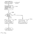
- Figure 10C depicts more detail of the exemplary process shown in Figure 10A when ORVR equipment is not present on the vehicle being fuelled.
- the detail relates to the vapour recovery control of the fuel dispensers vapour recovery system when the placement of a restrictor plate 31 in the fill neck 22 of a fuel tank 420 is known.
- the nozzle spout 28 typically extends through a restrictor plate 31 in the fuel tanks fill neck 22.
- the nozzle 28 includes a plurality of apertures 29 communicating with the vapour return passage.
- the restrictor plate31 substantially blocks the fuel tanks fill neck 22 and includes an opening sized to allow the nozzle spout to extend through during fuelling. The opening may have a door, which closes when the vehicle is not being fuelled.
- vent tube 33 running from a top portion of the tank to a point near the end of the fill neck.
- Certain fuel tanks have the vents extending past the restrictor plate, such that vapours vented from the top of the tank through the vent tube are placed back into the fill neck between the restrictor plate and the outside of the vehicle, while other tanks balance vapours via the vent tube 33 back into the fill neck 22 between the fuel tank 20 and the restrictor plate 31 as shown in Figure 3.
- the vent tube 11 connects to the fill neck 2 below the restrictor plate 5
- the vapours are concentrated in the confined area just before the restrictor plate near the end of the fill neck.
- an embodiment of the present invention is adapted to determine the placement of the restrictor plate relative to the vapour return inlet of the vent tube and control vapour recovery accordingly. Again, the information will be provided by the transponder 164 of the vehicle 14 (block 326). If the inlet is above the restrictor plate (block 328), the control system will preferably operate the dispensers vapour recovery system at a higher flow rate (block 330) given the increased difficulty in recovering vapours in the relatively uncontained area between the restrictor plate and ambient near the very end of the fill neck.
- the control system will operate the dispensers vapour recovery system at a lower flow rate (block 332) because the fuel vapours will be highly concentrated and contained below the restrictor plate near an upper portion of the fill neck. Once the vapour recovery control is set, the process will return to block 308 of Figure 10A.
- vapour recovery control function provides a vapour recovery control function to optimize vapour recovery for a particular vehicle and/or fuel tank configuration with or without ORVR equipment.
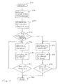
- the process begins (block 340) where signals are received from a transponder (block 342). From these signals, the control system determines a vapour recovery control function (block 344).
- the control function may take many forms and be dependent upon a number of different variables.
- the variables may be vehicle specific, such as ullage values, fuel quantities, temperature, pressure, or any combination thereof, to name a few.
- the variables may also be non-vehicle specific, such as time, flow rate, vapour recovery flow rate or amount of fuel delivered. Additionally, the function may be a constant representing a fixed flow rate for a particular vehicle or tank configuration.
- the control system will determine whether or not the vapour recovery control function is dependent upon a vehicle-specific variable (block 346). If the function is dependent upon a vehicle-specific variable, the control system will receive or calculate the variable and control function (block 348) and control the vapour recovery system accordingly (block 350). The system will then monitor for the end of fuelling (block 352). If fuelling is not at an end, the process may include a loop to repeat in which a new value is either received from the vehicle or calculated at the control system to arrive at a flow rate according to the vapour recovery function.
- control system may continuously monitor the new ullage values from the vehicle or calculate the new ullage values based on the original ullage value and the amount of fuel delivered, which is a value capable of being determined by the dispenser.
- the process ends (block 360).
- vapour recovery control function is not dependent upon the vehicle variable (block 346), the appropriate variables are determined, if necessary, at the control system (block 354).
- the vapour recovery control function will be calculated based on the desired variables, and the vapour recovery system is controlled accordingly (block 356).
- the control system will repeat the process until the end of fuelling (blocks 358, 360).
- the vapour recovery control function is a constant, the control system need not update the control function throughout the fuelling process.
- certain embodiments may require a combination of a constant vapour recovery flow rate for one portion of the fuelling operation and a variable flow rate for another portion of the fuelling operation.
- the dispenser's vapour recovery system operate to supply an amount of air to the storage tank required to replenish the volume of liquid taken from the tank during the fuelling operation to minimize or eliminate tank breathing loses discussed above.
- the transponder 164 of the vehicle 100 and dispenser may also communicate information relating to the effectiveness or the presence of a malfunction of the ORVR system.
- the dispenser may further modify or activate the vapour recovery system accordingly to minimize the escape of vapours during the fuelling operation.
- any of the above control functions may be altered, influenced, or otherwise affected by the central control system 50 in an effort to improve overall site efficiency and not merely an efficiency at a single dispenser.
- vapour recovery control options are available. Appropriate control of the fuel dispensers and underground storage tanks vapour handling systems as well as the vent reduces underground fuel tank pressure and thereby reduces loses due to fugitive emissions and reduces wear and unnecessary use of assist-type vapour recovery systems when operation would be redundant.
- the vapour recovery system may provide enough ambient air to the underground tank, so that when the air saturates, the hydrocarbon saturated air volume is approximately equal to the amount of fuel dispensed, thereby minimizing pressure fluctuations in the underground tanks.
- Another option, particularly useful with liquid driven vapour pumps is to use an output of the control system to open a dispenser valve or tank vent valve 19 is to ambient to redirect the air flow of the vapour recovery passage to atmosphere through an ambient vent.
Landscapes
- Engineering & Computer Science (AREA)
- Mechanical Engineering (AREA)
- Physics & Mathematics (AREA)
- Fluid Mechanics (AREA)
- Loading And Unloading Of Fuel Tanks Or Ships (AREA)
- Cooling, Air Intake And Gas Exhaust, And Fuel Tank Arrangements In Propulsion Units (AREA)
- Separation By Low-Temperature Treatments (AREA)
- Feeding, Discharge, Calcimining, Fusing, And Gas-Generation Devices (AREA)
- Production Of Liquid Hydrocarbon Mixture For Refining Petroleum (AREA)
- Combined Controls Of Internal Combustion Engines (AREA)
Claims (26)
- Dampf-Managementsystem für Tankstellen mit:dadurch gekennzeichnet, dass die Steuerung so ausgebildet ist, um eine Gesamtkohlenwasserstoffemission von der Tankstelle dadurch zu steuern, dass ein Gesamtverhältnis von rückgewonnenem Dampf zu abgegebener Flüssigkeit (V/L-Verhältnis) der Tankstelle bestimmt wird, und einen Nebensystembetrieb zu steuern, um das Gesamt-V/L-Verhältnis innerhalb vorbestimmter Grenzen beizubehalten.a. einer Vielzahl von Nebensystemen zur Dampfhandhabung; undb. einer Steuerung (50) in Verbindung mit der Vielzahl von Nebensystemen (19, 14) zur Dampfhandhabung, die derart ausgebildet ist, um einen Betrieb der Vielzahl von Nebensystemen (19, 14) zur Dampfhandhabung zu überwachen,
- System nach Anspruch 1,
wobei die Steuerung (50) so ausgebildet ist, um einen Nebensystembetrieb zu steuern und einen Kohlenwasserstoffdampfaustrag innerhalb vorbestimmter Grenzen beizubehalten. - System nach einem der Ansprüche 1 oder 2,
wobei die vorbestimmten Grenzen von Parametern in Bezug auf die Tankstelle, die durch die Steuerung (50) überwacht wird, abhängen. - System nach einem der vorhergehenden Ansprüche,
wobei zumindest eines der Nebensysteme ein Dampfrückgewinnungssystem (14, 60) einer Kraftstoffabgabeeinrichtung ist, das durch die Steuerung (50) gesteuert wird, um Gesamtkohlenwasserstoffemissionen zu steuern. - System nach Anspruch 4,
wobei das Dampfrückgewinnungssystem einer Kraftstoffabgabeeinrichtung einen Signalgenerator (60) umfasst, um ein Signal an die Steuerung (50) zu liefern, das zumindest einen Betriebsparameter des Dampfrückgewinnungssystems angibt. - System nach einem der Ansprüche 4 oder 5,
wobei die Steuerung (50) den Betrieb zumindest einer anderen Kraftstoffabgabeeinrichtung (14) berücksichtigt, um Gesamtkohlenwasserstoffemissionen zu steuern. - System nach einem der Ansprüche 4, 5 oder 6,
mit einem Fahrzeugunterscheidungssystem (152), das in der Lage ist, um zu bestimmen, ob ein Fahrzeug, das an einer Abgabeeinrichtung betankt wird, mit einem Dampfrückgewinnungssystem an Bord (ORVR-System) ausgerüstet ist. - System nach Anspruch 7,
wobei die Steuerung den Betrieb zumindest eines Dampfrückgewinnungssystems (60, 14) in Abhängigkeit von dem überwachten Betrieb von sowohl dem Dampfrückgewinnungssystem (60, 14) als auch dem Fahrzeugunterscheidungssystem (152) steuert. - System nach einem der Ansprüche 4 bis 8,
mit einem Fahrzeugunterscheidungssystem (152), das dazu in der Lage ist, um zu bestimmen, ob ein Fahrzeug, das an einer Abgabeeinrichtung (14) betankt wird, mit einem Dampfrückgewinnungssystem an Bord (ORVR-System) ausgerüstet ist, wobei die Betriebsparameter des Dampfrückgewinnungssystems der Kraftstoffabgabeeinrichtung zumindest eines der folgenden umfassen: das V/L-Verhältnis der Kraftstoffabgabeeinrichtung, die Kohlenwasserstoffkonzentration des Dampfes, der von der Kraftstoffabgabeeinrichtung (18) an den Untergrundtank (5) zurückgeführt wird, die Anzahl von ORVR- und Nicht-ORVR-Fahrzeugen, die in einem gegebenen Zeitrahmen betankt werden, und die Betriebsdrehzahl / geschwindigkeit einer Dampfpumpe. - System nach einem der Ansprüche 4 bis 9,
mit zumindest einem Untergrundtank (5) zur Kraftstoffspeicherung mit einer atmosphärischen Entlüftung (17) und zumindest einem Sensor (65, 67, 68) zur Messung eines Tankparameters, der Dampfzustände in den Speichertank (5) beeinflusst; wobei die Steuerung (50) derart ausgebildet ist, um Nebensysteme zur Dampfhandhabung durch Überwachung eines Tankparameters zu überwachen, der einen Dampfzustand in dem Speichertank beeinflusst. - System nach Anspruch 10,
wobei der Tankparameter zumindest einer aus der Gruppe ist, die umfasst: Tankleerraumdruck, Tankleerraumtemperatur und Kohlenwasserstoffkonzentration des Dampfes der atmosphärischen Entlüftung des Tankes. - System nach Anspruch 10 oder 11,
ferner mit zumindest einem Umgebungssensor (61, 63) zur Messung eines Umgebungsparameters, wobei die Steuerung (50) die Dampfrückgewinnungssysteme (60, 14) der Abgabeeinrichtung auf Grundlage des Umgebungsparameters in Verbindung mit dem Tankparameter steuert. - System nach einem der vorhergehenden Ansprüche,
mit einem Untergrund-Kraftstofftank (5), wobei ein Nebensystem ein Leerraumdrucksteuersystem (19, 69) ist, um den Druck in dem Untergrundtankleerraum zu überwachen und den Untergrunddruck zu steuern, wobei die Steuerung (50) so ausgebildet ist, um den Betrieb des Steuersystems (19, 69) für den Leerraumdruck zu überwachen und den Betrieb des Steuersystems (19, 69) für den Leerraumdruck zu steuern, um den Druck innerhalb vorbestimmter Grenzen beizubehalten, wobei der Betrieb zumindest eines anderen Nebensystems berücksichtigt wird. - System nach Anspruch 11 oder 12,
wobei die Steuerung (50) ferner derart ausgebildet ist, um Leckagen in dem Tank (5) und den Dampfrückgewinnungssystemen (8) durch Schließen einer Tankentlüftung (19) und Überwachen von Druckänderungen in dem Speichertank (5) oder dem Dampfrückgewinnungssystem (8) zu detektieren, was eine Dampfleckage anzeigt. - System nach einem der vorhergehenden Ansprüche,
wobei die Steuerung (50) ein trainiertes künstliches neuronales Netzwerk umfasst, dessen Eingänge zumindest Betriebsparameter des Nebensystems zur Handhabung von Dampf, Umgebungsdruck und Temperatur umfassen, und dessen Ausgänge zumindest Steueranweisungen für die Nebensysteme zur Handhabung von Dampf umfassen. - System nach einem der vorhergehenden Ansprüche,
mit zumindest einem Umgebungstemperatursensor (61), der mit der Steuerung verbunden ist, um Umgebungstemperaturinformation an die Steuerung zu liefern. - System nach einem der vorhergehenden Ansprüche,
ferner mit zumindest einem Sensor (63) für atmosphärischen Druck, der mit der Steuerung verbunden ist, um eine Information bezüglich atmosphärischem Druck an die Steuerung zu liefern. - System nach einem der vorhergehenden Ansprüche,
mit einem Fahrzeugunterscheidungssystem bezüglich Dampfrückgewinnung an Bord (ORVR-Fahrzeugunterscheidungssystem), das in der Läge ist, zu bestimmen, ob ein Fahrzeug, das an einer Kraftstoffabgabeeinrichtung betankt wird, mit einem ORVR-Dampfrückgewinnungssystem ausgerüstet ist. - System nach einem der vorhergehenden Ansprüche,
wobei zumindest eines der Nebensysteme zur Handhabung von Dampf ein Steuersystem (69) für den Leerraumdruck eines Untergrundtankes ist. - System nach Anspruch 19,
wobei das Steuersystem (69) für den Leerraum eines Untergrundtanks einen Signalgenerator umfasst, um ein Signal an die Steuerung (50) zu liefern, das zumindest eines der folgenden umfasst: Tankleerraumdruck, Kohlenwasserstoffdampfkonzentration des Tankleerraums, Tankleerraumtemperatur oder Kohlenwasserstoffdampfkonzentration der Tankentlüftung. - System nach einem der vorhergehenden Ansprüche,
wobei die Steuerung (50) zumindest eines empfängt aus:a. individuellem V/L-Verhältnis einer Kraftstoffabgabeeinrichtung;b. Kohlenwasserstoffgehalt von Dampf, der an die Untergrundspeichertanks durch Dampfrückgewinnungssysteme von Kraftstoffabgabeeinrichtungen zurückgeführt wird;c. ORVR-Fahrzeugstatus von Fahrzeugen, die an einer Kraftstoffabgabeeinrichtung betankt werden;d. Umgebungstemperatur der Tankstelle; unde. atmosphärischer Umgebungsdruck der Tankstelle. - System nach einem der vorhergehenden Ansprüche,
wobei die Steuerung (50) Leerraumzustände des Untergrundtanks empfängt. - System nach Anspruch 22,
wobei die Leerraumzustände des Untergrundtanks zumindest eines aus der Gruppe umfassen, die besteht aus: Leerraumdruck, Leerraumtemperatur, Kohlenwasserstoffdampfgehalt des Leerraums, Kohlenwasserstoffdampfkonzentration in einer Untergrundtankentlüftung. - System nach einem der vorhergehenden Ansprüche,
wobei die Steuerung Umgebungstemperatur- und Umgebungsdruckdaten empfängt. - Kraftstoffabgabeeinrichtung mit:a. einem Dampfrückgewinnungssystem zur Rückführung von Dämpfen von einem Fahrzeugkraftstofftank an einen Untergrundtank einer Tankstelle; undb. eine elektronische Schnittstelle mit einer Steuerung entfernt von der Kraftstoffabgabeeinrichtung, die dazu in der Lage ist, den Betrieb des Dampfrückgewinnungssystems zu überwachen und den Betrieb des Dampfrückgewinnungssystems zu steuern, wobei der Betrieb eines weiteren Dampfrückgewinnungssystems zumindest einer anderen Kraftstoffabgabeeinrichtung berücksichtigt wird, um einen Kohlenwasserstoffdampfaustrag von der Tankstelle innerhalb vorbestimmter Grenzen beizubehalten.
- Kraftstoffabgabeeinrichtung nach Anspruch 25,
ferner mit einem Fahrzeugunterscheidungssystem zur Bestimmung, ob ein Fahrzeug, das an einer Abgabeeinrichtung betankt wird, mit einem ORVR-System ausgerüstet ist.
Applications Claiming Priority (2)
| Application Number | Priority Date | Filing Date | Title |
|---|---|---|---|
| US15039298A | 1998-09-09 | 1998-09-09 | |
| US150392 | 1998-09-09 |
Publications (2)
| Publication Number | Publication Date |
|---|---|
| EP0985634A1 EP0985634A1 (de) | 2000-03-15 |
| EP0985634B1 true EP0985634B1 (de) | 2002-07-31 |
Family
ID=22534317
Family Applications (1)
| Application Number | Title | Priority Date | Filing Date |
|---|---|---|---|
| EP99307139A Expired - Lifetime EP0985634B1 (de) | 1998-09-09 | 1999-09-09 | Kraftstoffdampfüberwachungsvorrichtung in Tankanlagen |
Country Status (5)
| Country | Link |
|---|---|
| US (1) | US6302165B1 (de) |
| EP (1) | EP0985634B1 (de) |
| AU (1) | AU753504B2 (de) |
| DE (1) | DE69902328T2 (de) |
| NZ (1) | NZ337729A (de) |
Cited By (3)
| Publication number | Priority date | Publication date | Assignee | Title |
|---|---|---|---|---|
| US7258001B2 (en) | 2004-02-27 | 2007-08-21 | Fafnir Gmbh | Ventilation mast monitoring system for filling stations |
| CN101720301B (zh) * | 2007-05-04 | 2012-06-20 | 詹姆斯·W·希利 | 蒸汽容纳系统 |
| WO2026078487A3 (en) * | 2024-10-07 | 2026-05-21 | I.S.I.F. S.R.L. | Device for the detection and quantification of gaseous hydrocarbon leaks from a buried pipeline |
Families Citing this family (23)
| Publication number | Priority date | Publication date | Assignee | Title |
|---|---|---|---|---|
| US6622757B2 (en) | 1999-11-30 | 2003-09-23 | Veeder-Root Company | Fueling system vapor recovery and containment performance monitor and method of operation thereof |
| US6901786B2 (en) | 1999-11-30 | 2005-06-07 | Veeder-Root Company | Fueling system vapor recovery and containment leak detection system and method |
| US6347649B1 (en) | 2000-11-16 | 2002-02-19 | Marconi Commerce Systems Inc. | Pressure sensor for a vapor recovery system |
| FR2823191B1 (fr) * | 2001-04-06 | 2003-09-05 | Tokheim Services France | Procede de controle de la teneur en hydrocarbures d'une vapeur circulant dans une installation equipee d'un systeme d'aspiration de vapeur |
| US6805173B2 (en) | 2002-01-11 | 2004-10-19 | Healy Systems, Inc. | Vapor space pressure control system for underground gasoline storage tank |
| WO2003059800A1 (en) * | 2002-01-11 | 2003-07-24 | Healy Systems, Inc. | Vapour space pressure control system for underground gasoline storage tank |
| CA2425462C (en) * | 2002-04-11 | 2011-08-16 | Leroy G. Hagenbuch | Baffled tank for a vehicle |
| US6644360B1 (en) * | 2002-05-06 | 2003-11-11 | Gilbarco Inc. | Membrane and sensor for underground tank venting system |
| US6761190B2 (en) * | 2002-06-21 | 2004-07-13 | Gilbarco Inc. | Underground storage tank vapor pressure equalizer |
| US7260499B2 (en) | 2002-08-20 | 2007-08-21 | Fe Petro Inc. | Fuel delivery system with enhanced functionality and diagnostic capability |
| US6923221B2 (en) * | 2003-12-04 | 2005-08-02 | Gilbarco Inc. | Vapor recovery system with ORVR compensation |
| US7024317B1 (en) * | 2004-11-22 | 2006-04-04 | Anthony George | Apparatus and method for fuel measurement and accountability |
| US20070131281A1 (en) * | 2005-12-13 | 2007-06-14 | Delaware Capital Formation, Inc. | Underground fuel tank vent valve |
| US8060335B2 (en) * | 2006-04-13 | 2011-11-15 | Arid Technologies, Inc. | Method and system for liquid and vapor leak detection |
| US7909069B2 (en) | 2006-05-04 | 2011-03-22 | Veeder-Root Company | System and method for automatically adjusting an ORVR compatible stage II vapor recovery system to maintain a desired air-to-liquid (A/L) ratio |
| ITMO20060202A1 (it) * | 2006-06-21 | 2007-12-22 | Galliano Bentivoglio | Pistola per erogare combustibile liquido |
| US7681460B2 (en) * | 2007-04-20 | 2010-03-23 | Gilbarco Inc. | System and method for detecting pressure variations in fuel dispensers to more accurately measure fuel delivered |
| US7725271B2 (en) * | 2007-11-13 | 2010-05-25 | Gilbarco Inc. | Nozzle snap flow compensation |
| EP2439171A3 (de) | 2008-05-28 | 2012-07-18 | Franklin Fueling Systems, Inc. | Verfahren und Vorrichtung zur Überwachung von Einschränkungen in einem Stufe-II-Brennstoff-Dampfgewinnungssystem |
| US8191585B2 (en) | 2008-05-28 | 2012-06-05 | Franklin Fueling Systems, Inc. | Method and apparatus for monitoring for a restriction in a stage II fuel vapor recovery system |
| US8042376B2 (en) * | 2008-06-02 | 2011-10-25 | Gilbarco Inc. | Fuel dispenser utilizing pressure sensor for theft detection |
| WO2010135224A1 (en) | 2009-05-18 | 2010-11-25 | Franklin Fueling Systems, Inc. | Method and apparatus for detecting a leak in a fuel delivery system |
| CN113226949B (zh) | 2018-11-14 | 2023-06-02 | 富兰克林加油系统公司 | 压力真空阀 |
Family Cites Families (9)
| Publication number | Priority date | Publication date | Assignee | Title |
|---|---|---|---|---|
| US5195564A (en) * | 1991-04-30 | 1993-03-23 | Dresser Industries, Inc. | Gasoline dispenser with vapor recovery system |
| US5507325A (en) * | 1993-11-17 | 1996-04-16 | Finlayson; Ian M. | Vapor recovery system for fuel dispensers |
| US5484000A (en) * | 1994-04-01 | 1996-01-16 | Hasselmann; Detlev E. M. | Vapor recovery and processing system and method |
| DE59407054D1 (de) * | 1994-04-16 | 1998-11-12 | Scheidt & Bachmann Gmbh | Einrichtung zur Abgabe flüssiger Kraftstoffe |
| US5542458A (en) * | 1994-08-22 | 1996-08-06 | Gilbarco Inc. | Vapor recovery system for a fuel delivery system |
| US5605182A (en) * | 1995-04-20 | 1997-02-25 | Dover Corporation | Vehicle identification system for a fuel dispenser |
| US5671785A (en) * | 1995-08-15 | 1997-09-30 | Dresser Industries, Inc. | Gasoline dispensing and vapor recovery system and method |
| US5779097A (en) * | 1996-05-14 | 1998-07-14 | Delaware Capital Formation, Inc. | Vapor recovery system with integrated monitoring unit |
| US5782275A (en) * | 1996-05-17 | 1998-07-21 | Gilbarco Inc. | Onboard vapor recovery detection |
-
1999
- 1999-09-08 NZ NZ337729A patent/NZ337729A/xx unknown
- 1999-09-09 DE DE69902328T patent/DE69902328T2/de not_active Expired - Fee Related
- 1999-09-09 EP EP99307139A patent/EP0985634B1/de not_active Expired - Lifetime
- 1999-09-09 AU AU47472/99A patent/AU753504B2/en not_active Ceased
-
2000
- 2000-02-24 US US09/512,542 patent/US6302165B1/en not_active Expired - Lifetime
Cited By (3)
| Publication number | Priority date | Publication date | Assignee | Title |
|---|---|---|---|---|
| US7258001B2 (en) | 2004-02-27 | 2007-08-21 | Fafnir Gmbh | Ventilation mast monitoring system for filling stations |
| CN101720301B (zh) * | 2007-05-04 | 2012-06-20 | 詹姆斯·W·希利 | 蒸汽容纳系统 |
| WO2026078487A3 (en) * | 2024-10-07 | 2026-05-21 | I.S.I.F. S.R.L. | Device for the detection and quantification of gaseous hydrocarbon leaks from a buried pipeline |
Also Published As
| Publication number | Publication date |
|---|---|
| EP0985634A1 (de) | 2000-03-15 |
| AU4747299A (en) | 2000-03-16 |
| AU753504B2 (en) | 2002-10-17 |
| DE69902328D1 (de) | 2002-09-05 |
| DE69902328T2 (de) | 2002-12-05 |
| NZ337729A (en) | 2001-01-26 |
| US6302165B1 (en) | 2001-10-16 |
Similar Documents
| Publication | Publication Date | Title |
|---|---|---|
| AU753504B2 (en) | A service station vapour management system | |
| US5782275A (en) | Onboard vapor recovery detection | |
| US8573262B2 (en) | System and method for automatically adjusting an ORVR compatible stage II vapor recovery system to maintain a desired air-to-liquid (A/L) ratio | |
| US5450883A (en) | System and method for testing for error conditions in a fuel vapor recovery system | |
| US5956259A (en) | Intelligent fueling | |
| US5988232A (en) | Vapor recovery system employing oxygen detection | |
| US6532999B2 (en) | Pressure sensor for a vapor recovery system | |
| US7975528B2 (en) | Fueling system vapor recovery and containment performance monitor and method of operation thereof | |
| CA2135086A1 (en) | Vapor recovery system for fuel dispensers | |
| CA3024265C (fr) | Facility for storing and dispensing fuel | |
| EP1101729A1 (de) | Verfahren und Vorrichtung zur Leistungsdiagnose einer Dampfrückgewinnungsanlage | |
| US6644360B1 (en) | Membrane and sensor for underground tank venting system | |
| WO2018136585A1 (en) | Automatic liquid waste reservoir level control | |
| US6167923B1 (en) | Vapor recovery diagnostics | |
| CN108241351A (zh) | 一种非管输油气储运管控装置及系统 | |
| EP1739053B1 (de) | Gasrückführungssystem für Kraftstoff mit Temperatur-Sensor und Verfahren | |
| EP2241532B1 (de) | Brennstoffabgabeeinheit und Verfahren zur Steuerung einer solchen Brennstoffabgabeeinheit | |
| CA1048892A (en) | Method and system for handling volatile liquid vapors | |
| CN116328225B (zh) | 一种用于化工库区的储罐喷淋系统及方法 | |
| CN113884146A (zh) | 智慧燃气计量箱 | |
| MXPA00003663A (es) | Sistema de recuperacion de vapor que emplea deteccion de oxigeno | |
| WO2006120492A1 (en) | Vapour extraction device for fuel dispensers and operating method thereof | |
| AU4273500A (en) | Intelligent fuelling |
Legal Events
| Date | Code | Title | Description |
|---|---|---|---|
| PUAI | Public reference made under article 153(3) epc to a published international application that has entered the european phase |
Free format text: ORIGINAL CODE: 0009012 |
|
| AK | Designated contracting states |
Kind code of ref document: A1 Designated state(s): BE DE FR GB IT NL |
|
| AX | Request for extension of the european patent |
Free format text: AL;LT;LV;MK;RO;SI |
|
| RAP1 | Party data changed (applicant data changed or rights of an application transferred) |
Owner name: MARCONI COMMERCE SYSTEMS INC. |
|
| 17P | Request for examination filed |
Effective date: 20000912 |
|
| AKX | Designation fees paid |
Free format text: BE DE FR GB IT NL |
|
| 17Q | First examination report despatched |
Effective date: 20010125 |
|
| GRAG | Despatch of communication of intention to grant |
Free format text: ORIGINAL CODE: EPIDOS AGRA |
|
| GRAH | Despatch of communication of intention to grant a patent |
Free format text: ORIGINAL CODE: EPIDOS IGRA |
|
| GRAH | Despatch of communication of intention to grant a patent |
Free format text: ORIGINAL CODE: EPIDOS IGRA |
|
| GRAA | (expected) grant |
Free format text: ORIGINAL CODE: 0009210 |
|
| AK | Designated contracting states |
Kind code of ref document: B1 Designated state(s): BE DE FR GB IT NL |
|
| REG | Reference to a national code |
Ref country code: GB Ref legal event code: FG4D |
|
| REF | Corresponds to: |
Ref document number: 69902328 Country of ref document: DE Date of ref document: 20020905 |
|
| PGFP | Annual fee paid to national office [announced via postgrant information from national office to epo] |
Ref country code: FR Payment date: 20020910 Year of fee payment: 4 |
|
| PGFP | Annual fee paid to national office [announced via postgrant information from national office to epo] |
Ref country code: BE Payment date: 20021203 Year of fee payment: 4 |
|
| ET | Fr: translation filed | ||
| PLBE | No opposition filed within time limit |
Free format text: ORIGINAL CODE: 0009261 |
|
| STAA | Information on the status of an ep patent application or granted ep patent |
Free format text: STATUS: NO OPPOSITION FILED WITHIN TIME LIMIT |
|
| 26N | No opposition filed |
Effective date: 20030506 |
|
| PG25 | Lapsed in a contracting state [announced via postgrant information from national office to epo] |
Ref country code: BE Free format text: LAPSE BECAUSE OF NON-PAYMENT OF DUE FEES Effective date: 20030930 |
|
| BERE | Be: lapsed |
Owner name: *MARCONI COMMERCE SYSTEMS INC. Effective date: 20030930 |
|
| PG25 | Lapsed in a contracting state [announced via postgrant information from national office to epo] |
Ref country code: NL Free format text: LAPSE BECAUSE OF NON-PAYMENT OF DUE FEES Effective date: 20040401 |
|
| PG25 | Lapsed in a contracting state [announced via postgrant information from national office to epo] |
Ref country code: FR Free format text: LAPSE BECAUSE OF NON-PAYMENT OF DUE FEES Effective date: 20040528 |
|
| NLV4 | Nl: lapsed or anulled due to non-payment of the annual fee |
Effective date: 20040401 |
|
| REG | Reference to a national code |
Ref country code: FR Ref legal event code: ST |
|
| PGFP | Annual fee paid to national office [announced via postgrant information from national office to epo] |
Ref country code: DE Payment date: 20040902 Year of fee payment: 6 |
|
| PGFP | Annual fee paid to national office [announced via postgrant information from national office to epo] |
Ref country code: GB Payment date: 20040908 Year of fee payment: 6 |
|
| PG25 | Lapsed in a contracting state [announced via postgrant information from national office to epo] |
Ref country code: IT Free format text: LAPSE BECAUSE OF NON-PAYMENT OF DUE FEES Effective date: 20050909 Ref country code: GB Free format text: LAPSE BECAUSE OF NON-PAYMENT OF DUE FEES Effective date: 20050909 |
|
| PG25 | Lapsed in a contracting state [announced via postgrant information from national office to epo] |
Ref country code: DE Free format text: LAPSE BECAUSE OF NON-PAYMENT OF DUE FEES Effective date: 20060401 |
|
| GBPC | Gb: european patent ceased through non-payment of renewal fee |
Effective date: 20050909 |