EP0985855B1 - Stufenlos verstellbares Kegelscheibenumschlingungsgetriebe, insbesondere für Kraftfahrzeuge - Google Patents
Stufenlos verstellbares Kegelscheibenumschlingungsgetriebe, insbesondere für Kraftfahrzeuge Download PDFInfo
- Publication number
- EP0985855B1 EP0985855B1 EP99117546A EP99117546A EP0985855B1 EP 0985855 B1 EP0985855 B1 EP 0985855B1 EP 99117546 A EP99117546 A EP 99117546A EP 99117546 A EP99117546 A EP 99117546A EP 0985855 B1 EP0985855 B1 EP 0985855B1
- Authority
- EP
- European Patent Office
- Prior art keywords
- transmission
- elements
- torque
- designed
- belt
- Prior art date
- Legal status (The legal status is an assumption and is not a legal conclusion. Google has not performed a legal analysis and makes no representation as to the accuracy of the status listed.)
- Expired - Lifetime
Links
- 230000005540 biological transmission Effects 0.000 title claims abstract description 104
- 230000002093 peripheral effect Effects 0.000 claims description 16
- 230000001419 dependent effect Effects 0.000 claims description 15
- 238000013016 damping Methods 0.000 claims description 11
- 238000006073 displacement reaction Methods 0.000 claims description 4
- 239000012530 fluid Substances 0.000 abstract 1
- 238000005086 pumping Methods 0.000 abstract 1
- 238000013519 translation Methods 0.000 description 25
- 239000003921 oil Substances 0.000 description 19
- 238000003825 pressing Methods 0.000 description 12
- 238000007667 floating Methods 0.000 description 6
- 238000013461 design Methods 0.000 description 5
- 238000012549 training Methods 0.000 description 5
- 238000004146 energy storage Methods 0.000 description 4
- 230000008901 benefit Effects 0.000 description 3
- 230000008859 change Effects 0.000 description 3
- 230000004044 response Effects 0.000 description 3
- 238000005096 rolling process Methods 0.000 description 3
- 230000008878 coupling Effects 0.000 description 2
- 238000010168 coupling process Methods 0.000 description 2
- 238000005859 coupling reaction Methods 0.000 description 2
- 239000010720 hydraulic oil Substances 0.000 description 2
- 238000000034 method Methods 0.000 description 2
- 230000008569 process Effects 0.000 description 2
- 238000012546 transfer Methods 0.000 description 2
- 238000004891 communication Methods 0.000 description 1
- 238000010276 construction Methods 0.000 description 1
- 230000007423 decrease Effects 0.000 description 1
- 238000009826 distribution Methods 0.000 description 1
- 230000002996 emotional effect Effects 0.000 description 1
- 238000005516 engineering process Methods 0.000 description 1
- 230000001771 impaired effect Effects 0.000 description 1
- 230000003993 interaction Effects 0.000 description 1
- 230000007246 mechanism Effects 0.000 description 1
- 230000009467 reduction Effects 0.000 description 1
- 230000000284 resting effect Effects 0.000 description 1
- 238000007789 sealing Methods 0.000 description 1
Images

Classifications
-
- F—MECHANICAL ENGINEERING; LIGHTING; HEATING; WEAPONS; BLASTING
- F16—ENGINEERING ELEMENTS AND UNITS; GENERAL MEASURES FOR PRODUCING AND MAINTAINING EFFECTIVE FUNCTIONING OF MACHINES OR INSTALLATIONS; THERMAL INSULATION IN GENERAL
- F16H—GEARING
- F16H61/00—Control functions within control units of change-speed- or reversing-gearings for conveying rotary motion ; Control of exclusively fluid gearing, friction gearing, gearings with endless flexible members or other particular types of gearing
- F16H61/66—Control functions within control units of change-speed- or reversing-gearings for conveying rotary motion ; Control of exclusively fluid gearing, friction gearing, gearings with endless flexible members or other particular types of gearing specially adapted for continuously variable gearings
- F16H61/662—Control functions within control units of change-speed- or reversing-gearings for conveying rotary motion ; Control of exclusively fluid gearing, friction gearing, gearings with endless flexible members or other particular types of gearing specially adapted for continuously variable gearings with endless flexible members
- F16H61/66254—Control functions within control units of change-speed- or reversing-gearings for conveying rotary motion ; Control of exclusively fluid gearing, friction gearing, gearings with endless flexible members or other particular types of gearing specially adapted for continuously variable gearings with endless flexible members controlling of shifting being influenced by a signal derived from the engine and the main coupling
- F16H61/66263—Control functions within control units of change-speed- or reversing-gearings for conveying rotary motion ; Control of exclusively fluid gearing, friction gearing, gearings with endless flexible members or other particular types of gearing specially adapted for continuously variable gearings with endless flexible members controlling of shifting being influenced by a signal derived from the engine and the main coupling using only hydraulical and mechanical sensing or control means
Definitions
- the invention relates to a continuously variable conical pulley, the is intended in particular for use in motor vehicles, according to the The preamble of claim 1 and as of the generic DE-A-19546293 is known.
- Infinitely variable transmissions are in different training and arrangement in wide application areas of technology used.
- Well-known forms of training are Tapered belt, the cone pulley and the Toroidreibgetriebe.
- the training as a conical-pulley is used for a long time in motor vehicles, for example in the form of the known DAF Variomatic.
- one of the conical disks is axially displaceable and stands with two coaxially arranged and rotatable relative to each other cylindrical sleeves in Connection, one of which is left-handed and the other right-increasing Has helical surfaces of variable slope as end-face curved paths and the at axial displacements of the conical disk, which change the transmission ratio are required, so in opposite directions rotatable and together are axially displaceable that they are held in permanent contact with the support disk.
- the one sleeve by means of an axial Tension between the sleeve, the rolling elements and the support disc both the transmits introduced torque as well as a contact pressure to the conical disks, while the other sleeve counter to the direction of rotation of the transmitted torque until is turned to the contact with the rolling elements, to at a reversal of rotation without substantial idle bridging the torque and contact pressure transmission to take over.
- the curved paths provide in the circumferential direction variable pitch for a torque and translation dependent pressing force.
- the driven pulley set is a hydraulic actuator cylinder provided in conjunction with an electrohydraulic Transmission ratio control device for setting a predetermined Translation ratio is used.
- the hydraulic control is permanently from a Hydraulic pump fed, excess hydraulic oil is passed back into the oil tank.
- the present invention is based on the problem of the transmission efficiency improve.
- the infinitely variable conical-pulley transmission especially for Motor vehicles is provided, consists of two transmission parts, namely a drive part and a stripping section.
- Each gear part has in each case a shaft, on the two Conical disks, namely a fixed disk and a loose disk, which rotate against each other and formed axially displaceable and are arranged to a common axis of rotation are rotatably mounted.
- the gear parts are through a between the conical disks Guided traction means in connection.
- the conical-pulley has at least one of the Getriebemaschine a device for translation control on and is at least one the gear parts provided with a device for pressing control.
- the device for translation control is operated with auxiliary power and has a Energy generator, an energy storage, at least one translation actuator and a Control device, which are designed and arranged such that the Translation operators depending on a translation status and a Translation request both energy from the energy store fed as well Energy is removable, and that the power generator, if necessary, to supply the Energy storage can be put into operation and turned off.
- the device for Translation control relies on auxiliary energy.
- auxiliary energy This is insofar expedient, as the optimum transmission ratio substantially of parameters depends, which are determined outside of the transmission, so that a control from the outside is indispensable.
- the translation actuators are supplied from an energy store, so that the power generator only as needed, i. for refilling the energy store, must be put into operation.
- an energy storage for example, a pneumatic or hydraulic pressure vessel, an electrical accumulator, etc. understood become.
- the described intermittent operation requires the power generator only drive power when energy is actually required. This arrangement improves the efficiency of the transmission, whereby the problem posed is solved.
- the translation control device can be used as an electrohydraulic device be educated.
- an energy generator an oil pump can be provided and as Energy storage can be used a hydraulic pressure accumulator.
- the Translation actuators may be formed as hydraulic actuators, and as Control unit may be provided a transmission control unit, which is designed and is arranged that processed by sensors input signals and processed in Hydraulic lines arranged electro-hydraulic control valves are controlled, the hydraulic lines between the pressure accumulator and the actuators and can be arranged between the Stellzylindem and a non-pressurized oil tank.
- a hydraulic device has the advantage in a small construction volume and relatively low To be able to generate weight large forces.
- the electrical control results expedient from the use of a computer as a transmission control unit.
- the computer processes information supplied by sensors and controls the operation of the electrohydraulic control valves forces and movements by the hydraulic Actuators are generated.
- the hydraulic actuators which are essentially made respectively a Stellylinder and an adjusting piston can be single acting or double be effective. In single-acting training only an axial force is too produces a pushing together of the respective conical disks, a restoring force is then by an interaction between the conical disks and the traction means caused.
- the actuators can be arranged fixed to the housing or partially with rotate the rotating loose disk. For a fixed housing arrangement is a thrust bearing while required between the respective actuator and the associated floating disk at partially co-rotating arrangement corresponding expense for the sealing of rotating components must be operated against dormant components.
- the translation control device may include an electric motor, such is formed and arranged that the power generator driven by the electric motor is, and that the electric motor by the control unit, if necessary, in operation and except Operation is settable.
- an electric motor such is formed and arranged that the power generator driven by the electric motor is, and that the electric motor by the control unit, if necessary, in operation and except Operation is settable.
- a power generator in the present example, a pump, a generator, etc. understood, the mechanical energy in pressure or in electrical energy transforms.
- the use of an electric motor as an auxiliary drive has the advantage of being less Size and low weight can be easily supplied with energy via electrical lines and to be controllable.
- the device for the transmission control can also be a coupling device which is designed and arranged such that the energy generator mechanically is driven by a drive motor of the motor vehicle, and that the Clutch device required by the controller is closable and separable.
- a Such an arrangement requires no additional auxiliary drive, but uses as needed a part of the driving force of an existing anyway in the vehicle drive motor.
- the coupling device is mechanically formed.
- the device for pressing control can be designed as an automatic device and Have components, wherein a transmission component for transmitting a Torque of the shaft on one of the conical disks, a deflection component for Deflection of a torque-dependent circumferential force in an axial contact pressure, and a Supporting component may be provided to support the axial contact pressure.
- a transmission component for transmitting a Torque of the shaft on one of the conical disks a deflection component for Deflection of a torque-dependent circumferential force in an axial contact pressure
- a Supporting component may be provided to support the axial contact pressure.
- Such Self-acting device expediently works mechanically and uses the transmitted torque to build up a for the between the conical disks and the Traction required contact pressure.
- the transmission component may be rotatably connected to the shaft and one or have a plurality of transmission elements, which are designed and arranged such that a voltage applied to the shaft torque on the transmission elements in the form of Circumferential forces is effective and transferable.
- the deflection component can with the Losture communicate and have one or more active surfaces, the like formed and arranged inclined relative to the axis of rotation and the peripheral forces are that contact with the transmission elements can be produced.
- the torque can be absorbable by receiving the peripheral forces and by redirecting the Circumferential forces the axial contact pressure are generated.
- the Contact pressure between the conical disks and the traction means should be such that the torque introduced by slip friction is transferable, but not be much larger, otherwise the transmission efficiency by unnecessarily high Friction losses would worsen. It is therefore advantageous the Anpreß Kunststoffung so form, that the contact pressure generated in substantially proportional to transmitted torque behaves.
- transfer elements u. a. Balls, rolls and sliding blocks in question, wherein in principle elements with surface contact with the Wirklächen before such with line contact or point contact to avoid large Surface pressures are to be preferred.
- the transmission component can also rotatably connected to the loose disk and one or more transmission elements which are formed and arranged such that a voltage applied to the shaft Torque on the transmission elements in the form of circumferential forces can be received and is transferable.
- the deflection component is then in communication with the shaft and has one or more active surfaces, which are formed and compared to the Rotary axis and the circumferential forces are arranged inclined that contact with the Transmission elements can be produced.
- the torque is achieved by taking the Transmitted circumferential forces and the deflection of the circumferential forces is the axial Pressing force generated.
- the active surfaces of the deflection component can be used as a cam contour with in Circumferentially formed changed inclination and arranged so that the Transmission elements of the transmission component depending on a Translation-dependent axial displacement of the deflection component so with the Cam contour can be brought into contact that by the peripheral forces in dependence of the Inclination of the cam contour a torque-dependent and depending on the changed Inclination of the cam contour a translation-dependent axial contact force can be generated.
- the axial contact force of the transmitted torque is a function of Gear ratio produced. If the transmission ratio is increased, so decreases the effective diameter in the drive part of Belt-driven. For equally large introduced torque this requires a larger to be transmitted between the conical disks and the traction means Peripheral force and thus a greater axial contact pressure. When the output part of the transmission is conversely, since there the effective diameter at a magnification of the Translation ratio increased.
- the pressure control device may include a device for reducing Peak loads when changing from train operation to overrun operation and vice versa exhibit.
- a device for reducing Peak loads when changing from train operation to overrun operation and vice versa exhibit In mechanical devices of the type described may be due to the Bridging of empty play of the transfer elements between the active surface for Switzerland cafe and the effective surface for overrun to strong torque surges throughout Powertrain come. To a suitably stable design, with higher costs and higher weight would be to avoid and also the driving comfort is the use of a device to reduce peak loads meaningful.
- the device for pressing control can separate deflection components for train and Shunting operation, and the deflection components can be designed and be arranged that constantly contact with the transmission elements of the Transmission component exists. In such an arrangement are of load changes caused peak loads avoided or significantly weakened.
- the deflection components of the device for pressing control can with each other and / or with the floating disk via spring elements and / or damping elements in Connection stand.
- the spring elements By the spring elements, the deflection components in unloaded condition kept in a resting position in which they both contact with the associated transmission elements of the transmission component as well as with the Have loose disc.
- the gear ratio When occurring relative movements between these components, the by a reversal of direction of the transmitted torque or by an adjustment the gear ratio can be generated, generate the spring elements wegproportionale restoring forces and the damping elements speed proportional Restoring forces. The latter dampen faster movements faster than slow ones.
- the Spring elements ensure permanent contact of the deflection components with the associated transmission elements, while the damping elements occurring Load peaks due to a limited relative movement between the deflection components and remove the floating disk. This results in a comfortable and load changes material-friendly response.
- One required for translation adjustment Displaceability of the transmission elements to the cam contour is maintained.
- a device for generating a torque independent and translation independent Grundanpressung provided be.
- the Grundanpressung is advantageous in that thereby a vehicle standstill, i.e. with a small gear ratio and no transmitted torque, at one Starting process unnecessary slippage between the conical disks and the traction means avoided can be.
- the basic contact is easily by a the conical disks of a Gear part compressive coil spring or otherwise feasible. In this case, a single Grundanpressung in the drive part of the transmission is sufficient. in the Contrary to an arrangement in the output part, the arrangement in the drive part has the advantage that the basic pressure in this case automatically the current power requirement equivalent.
- the conical disks of the drive part When pushed together conical disks of the drive part is due a large effective diameter between the conical disks and the traction means a relatively small axial contact pressure for transmitting a predetermined torque needed and in the present embodiment by a largely relaxed spring provided.
- the conical disks of the drive part are pressed apart, it is the other way round. Due to a now small effective diameter between the conical disks and The traction means is now a large axial contact pressure for transmission of the predetermined Torque required and is due to the in this case more tensioned spring for Provided.
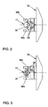
- FIG. 2 and FIG. 3 each show schematically Arrangements of devices for preventing torque peaks when changing from pull to push operation, which are intended for conical-pulley transmission.
- FIG. 1 shows a conical-pulley transmission 1 with an electrohydraulic drive Translation control device and a mechanical device for Anpreß horrung.
- the conical-pulley transmission 1 consists of a drive part 2a and a Output part 2b, which are connected via a traction means 3 in connection.
- Both gear parts 2 point Substantially identical components, so that substantially identical for both transmission parts 2 Reference numerals are used, wherein the reference numerals of the driven part 2b are deleted. To improve clarity, the same components are usually only in one of the transmission parts 2 provided with reference numerals.
- Both gear parts 2 each have a shaft 4, 4 'and two wedge disks 5, 5', namely a fixed disk 5a, 5a 'and a Losility 5b, 5b ', with a common axis of rotation 6, 6' on.
- the fixed disk 5a, 5a ' is each on the associated shaft 4, 4 'by means of needle bearings 7, 7' rotatably mounted and axially fixed.
- the loose disk 5b, 5b ' is by means of a ball guide 8, 8' relative to the associated fixed disk 5a, 5a 'axially displaceable, but rotatably mounted.
- the drive part 2a has a biasing spring 15, which has an axial Grundanpreßkraft 16 exerts on the local loose disk 5b.
- Both gear parts 2 have with Rollers 17, 17 'equipped roller axes 18, 18', with the respective shaft 4, 4 'fixed are connected.
- the rollers 17, 17 ' are in contact with active surfaces 19, 19' of the respective loose disk 5b, 5b '.
- the hydraulic actuators 10, 10 ' are via hydraulic lines 20, each with two Control valves 21a, 21b; 21c, 21d (21).
- the control valves 21 are as electromagnetically actuated and clocked two-way valves formed by a Transmission control unit 22 are controlled. At rest, the control valves 21 closed, opened in activated state.
- the first control valve 21 a is the Drive part 2a associated inlet valve and connects in the activated state one hydraulic pressure accumulator 23 with the hydraulic actuator 10 of the drive part 2a.
- the third control valve 21 c is a corresponding intake valve, the output part 2 b assigned.
- the second control valve 21b is associated with the drive part 2a Exhaust valve and connects in the activated state, the hydraulic actuator 10 of the Drive parts 2a with a non-pressurized oil tank 24.
- the fourth control valve 21d is a corresponding outlet valve which is associated with the output part 2b. From the oil tank 24 leads one of the hydraulic lines 20 via a filter element 25, one of an electric motor 26 drivable oil pump 27 and a check valve 28 in the hydraulic pressure accumulator 23. In parallel there is a pressure relief valve 29.
- a pressure sensor 30 In the area of hydraulic accumulator 23 is a pressure sensor 30, which has an electrical Control line 31 is connected to the transmission control unit 22.
- input signals 32 are routed, i.a. the input signal 32 of the pressure sensor 30, and output signals 33 via electrical working lines 34 to the control valves 21 and passed to the electric motor 26.
- the translation control device operates electrohydraulically.
- the oil pump 27 delivers hydraulic oil from the oil tank 24 through one of the hydraulic lines 20 via the Filter element 25 in the hydraulic pressure accumulator 23.
- the oil pump 27 is required driven by the electric motor 26 by an effective pressure in the accumulator 23 pressure permanently picked up by the connected pressure sensor 30 and via the electrical control line 31 is forwarded to the transmission control unit 22.
- the electric motor 26 and thus the oil pump 27 at Falling below a specified lower pressure in the accumulator 23 is set in operation and turned off upon reaching a predetermined upper pressure.
- the oil pump 27 is so operated intermittently.
- the between the accumulator 23 and the oil pump 27th arranged check valve 28 prevents emptying of the pressure accumulator 23 in the Oil tank 24 with stationary oil pump 27.
- the parallel-connected pressure relief valve 29th prevented by a pressure-dependent connection of the pressure accumulator 23 with the oil tank 24th an exceeding of a fixed maximum pressure in the pressure accumulator 23rd
- a Reduction of the gear ratio is done analogously in the same way, that the hydraulic actuator 10 'of the output part 2b via the third control valve 21c with the pressure accumulator 23 is connected, while the hydraulic actuator 10 of the Drive part 2a via the second control valve 21b depressurized to the oil tank 24 is switched.
- the device for pressing control works automatically mechanically, so no need Power supply, and is present in the present example on both transmission parts 2.
- One in each case on the shaft 4, 4 'effective torque is fixed to the shaft 4, 4' associated roller axes 18, 18 'on the rotatable rollers 17, 17' transferred, where the torque in the form of circumferential forces is effective.
- the rollers 17, 17 ' are in contact with the active surfaces 19, 19 'of the respective loose disk 5b, 5b'.
- the Active surfaces 19, 19 ' have an inclination relative to the axis of rotation 6, 6' and opposite the peripheral forces.
- the arranged on the drive part 2a biasing spring 15 provides an axial Grundanpressung 16, which is translation-independent, and in particular at a vehicle standstill a slip-free and therefore low-wear start-up allows.
- FIG. 2 shows a schematic arrangement of components for the transmission of a Torque and for generating an axial pressure force 35, 35 'in one Tapered belt transmission 1 according to Fig. 1.
- deflection components 36 There are two deflection components 36, namely one for train operation 36a and one for overrun operation 36b. Both Deflection components 36 are connected via a spring element 37 with each other and each a damping element 38 with one of the loose washers 5b, 5b 'of FIG. 1 in conjunction.
- the spring element 37 both deflection components 36 with their Active surfaces 19, 19 'to a roller 17, 17' of FIG. 1 is pressed.
- both deflection components 36 By a constant contact of both deflection components 36 with the force-transmitting roller 17, 17 'is in connection with a relation to the loose disk 5b, 5b 'muted connection to provide a steady and comfortable response Load changes, especially when a change from pull to overrun, achieved. Load peaks in the drive train are avoided or at least greatly reduced.
- the spring element 37 is used in an advantageous manner for generating the axial basic pressing 16, so that the biasing spring 15 of FIG. 1 can be omitted.
- FIG. 3 shows a similar arrangement as in FIG. 2.
- Attachment of the deflection components 36 is one of the deflection components 36 connected via one of the damping elements 38 with the loose disk 5b, 5b ', while the other deflection component 36 via the spring element 37 and one of Damping elements 38 are interconnected.
Landscapes
- Engineering & Computer Science (AREA)
- General Engineering & Computer Science (AREA)
- Mechanical Engineering (AREA)
- Transmissions By Endless Flexible Members (AREA)
- Pulleys (AREA)
- Transmission Devices (AREA)
Description
- 1
- Kegelscheibenumschlingungsgetriebe
- 2
- Getriebeteil
- 2a
- Antriebsteil
- 2b
- Abtriebsteil
- 3
- Zugmittel
- 4
- Welle
- 4'
- Welle
- 5
- Kegelscheibe
- 5'
- Kegelscheibe
- 5a
- Festscheibe
- 5a'
- Festscheibe
- 5b
- Losscheibe
- 5b'
- Losscheibe
- 6
- Drehachse
- 6'
- Drehachse
- 7
- Nadellager
- 7'
- Nadellager
- 8
- Kugelführung
- 8'
- Kugelführung
- 9
- Außenseite (der Losscheibe)
- 9'
- Außenseite (der Losscheibe)
- 10
- hydraulisches Stellglied
- 10'
- hydraulisches Stellglied
- 11
- Verstellkolben
- 11'
- Verstellkolben
- 12
- Verstellzylinder
- 12'
- Verstellzylinder
- 13
- Axiallager
- 13'
- Axiallager
- 14
- axiale Stellkraft
- 15
- Vorspannfeder
- 16
- axiale Grundanpressung
- 17
- Rolle
- 17'
- Rolle
- 18
- Rollenachse
- 18'
- Rollenachse
- 19
- Wirkfläche (der Losscheibe)
- 19'
- Wirkfläche (der Losscheibe)
- 20
- Hydraulikleitung
- 21
- Steuerventil
- 21a
- erstes Steuerventil
- 21b
- zweites Steuerventil
- 21c
- drittes Steuerventil
- 21d
- viertes Steuerventil
- 22
- Getriebesteuergerät
- 23
- hydraulischer Druckspeicher
- 24
- Öltank
- 25
- Filterelement
- 26
- Elektromotor
- 27
- Ölpumpe
- 28
- Rückschlagventil
- 29
- Druckbegrenzungsventil
- 30
- Drucksensor
- 31
- elektrische Steuerleitung
- 32
- Eingangssignal
- 33
- Ausgangssignal
- 34
- elektrische Arbeitsleitung
- 35
- axiale Anpreßkraft
- 35'
- axiale Anpreßkraft
- 36
- Umlenkungskomponente
- 36a
- Umlenkungskomponente für Zugbetrieb
- 36b
- Umlenkungskomponente für Schubbetrieb
- 37
- Federelement
- 38
- Dämpfungselement
Claims (10)
- Stufenlos verstellbares Kegelscheibenumschlingungsgetriebe (1), insbesondere für Kraftfahrzeuge, mit zwei jeweils eine Welle (4, 4') aufweisenden Getriebeteilen (2) - einem Antriebsteil (2a) und einem Abtriebsteil (2b) - wobei auf jeder der Wellen (4, 4') jeweils zwei gegeneinander drehfest und axialverschiebbar ausgebildete und angeordnete Kegelscheiben (5, 5') - eine Festscheibe (5a, 5a') und eine Losscheibe (5b, 5b') - um eine gemeinsame Drehachse (6, 6') drehbar gelagert sind, mit einem zwischen den Kegelscheiben (5, 5') geführten und die Getriebeteile (2) verbindenden Zugmittel (3), mit einer in jeder der Getriebeteile (2) angeordneten Vorrichtung zur Drehmomentübertragung zwischen der Welle (4, 4') und den Kegelscheiben (5, 5'), mit einer mindestens an einem der Getriebeteile (2) vorhandenen Vorrichtung zur Übersetzungsteuerung, und mit einer mindestens an einem der Getriebeteile (2) vorgesehenen Vorrichtung zur Anpresssteuerung, wobei die Vorrichtung zur Übersetzungssteuerung mit Hilfsenergie betreibbar ist und einen Energieerzeuger, einen Energiespeicher und mindestens ein Übersetzungsstellglied und ein Steuergerät (22) aufweist, die derart ausgebildet und angeordnet sind, dass dem Übersetzungsstellglied oder den Übersetzungsstellgliedern in Abhängigkeit von einem Übersetzungsstatus und einer Übersetzungsanforderung sowohl Energie aus dem Energiespeicher zuführbar als auch Energie entnehmbar ist, wobei die Vorrichtung zur Übersetzungssteuerung als elektrohydraulische Vorrichtung ausgebildet ist, nämlich als Energieerzeuger eine Ölpumpe (27) vorgesehen ist, dadurch gekennzeichnet, dass als Energiespeicher ein hydraulischer Druckspeicher (23) vorgesehen ist, dass die Vorrichtung zur Übersetzungssteuerung einen Elektromotor (26) aufweist, der derart ausgebildet und angeordnet ist, dass die Ölpumpe (27) von dem Elektromotor (26) antreibbar ist, und dass der Elektromotor (26) durch das Steuergerät (22) bedarfsweise zur Versorgung des Energiespeichers in Betrieb und außer Betrieb setzbar ist und dann die Ölpumpe (27) intermittierend antreibt.
- Kegelscheibenumschlingungsgetriebe nach Anspruch 1, dadurch gekennzeichnet, daß die Übersetzungsstellglieder als hydraulische Stellglieder (10, 10') ausgebildet sind, und daß als Steuergerät ein Getriebesteuergerät (22) vorgesehen ist, das derart ausgebildet und angeordnet ist, daß von Sensoren übertragene Eingangssignale (32) verarbeitbar und in Hydraulikleitungen (20) angeordnete elektrohydraulische Steuerventile (21) ansteuerbar sind, wobei die Hydraulikleitungen (20) zwischen dem Druckspeicher (23) und den Stellgliedern (10, 10') und zwischen den Stellgliedern (10, 10') und einem drucklosen Öltank (24) angeordnet sind.
- Kegelscheibenumschlingungsgetriebe nach einem der Ansprüche 1 oder 2, dadurch gekennzeichnet, daß
die Vorrichtung zur Anpreßsteuerung als selbsttätige Vorrichtung ausgebildet ist und Komponenten aufweist, wobei eine Übertragungkomponente zur Übertragung eines Drehmomentes von der Welle (4, 4') auf eine der Kegelscheiben (5, 5'), eine Umlenkungskomponente (36) zur Umlenkung einer drehmomentabhängigen Umfangskraft in eine axiale Anpreßkraft (35, 35'), und eine Stützkomponente zur Abstützung der axialen Anpreßkraft (35, 35') vorgesehen ist. - Kegelscheibenumschlingungsgetriebe nach Anspruch 3, dadurch gekennzeichnet, daß die Übertragungskomponente drehfest mit der Welle (4, 4') verbunden ist und ein oder mehrere Übertragungselemente aufweist, die derart ausgebildet und angeordnet sind, daß ein an der Welle (4, 4') anliegendes Drehmoment an den Übertragungselementen in Form von Umfangskräften wirksam und übertragbar ist, und daß die Umlenkungskomponente (36) mit der Losscheibe (5b, 5b') in Verbindung steht und ein oder mehrere Wirkflächen (19, 19') aufweist, die derart ausgebildet und gegenüber der Drehachse (6, 6') und den Umfangskräften geneigt angeordnet sind, daß Kontakt mit den Übertragungselementen herstellbar ist, daß das Drehmoment durch Aufnahme der Umfangskräfte übertragbar ist, und daß durch Umlenkung der Umfangskräfte die axiale Anpreßkraft (35) erzeugbar ist.
- Kegelscheibenumschlingungsgetriebe nach Anspruch 3, dadurch gekennzeichnet, daß die Übertragungskomponente drehfest mit der Losscheibe (5b, 5b') verbunden ist und ein oder mehrere Übertragungselemente aufweist, die derart ausgebildet und angeordnet sind, daß ein Drehmoment von den Übertragungselementen in Form von Umfangskräften aufnehmbar und übertragbar ist, und daß die Umlenkungskomponente (36) mit der Welle (4, 4') in Verbindung steht und ein oder mehrere Wirkflächen (19, 19') aufweist, die derart ausgebildet und gegenüber der Drehachse (6, 6') und den Umfangskräften geneigt angeordnet sind, daß Kontakt mit den Übertragungselementen herstellbar ist, daß das Drehmoment durch Übertragung der Umfangskräfte übertragbar ist, und daß durch Umlenkung der Umfangskräfte die axiale Anpreßkraft (35) erzeugbar ist.
- Kegelscheibenunischlingungsgetriebe nach einem der Ansprüche 4 oder 5, dadurch gekennzeichnet, daß
die Wirkflächen (19, 19') als Nockenkontur mit in Umfangsrichtung veränderter Neigung ausgebildet und derart angeordnet sind, daß die Übertragungselemente der Übertragungskomponente abhängig von einer übersetzungsabhängigen axialen Verschiebung der Umlenkungskomponente (36) derart mit der Nockenkontur in Kontakt bringbar sind, daß durch die Umfangskräfte in Abhängigkeit der Neigung der Nockenkontur eine drehmomentabhängige und in Abhängigkeit der veränderten Neigung der Nockenkontur eine übersetzungsabhängige axiale Anpreßkraft (35, 35') erzeugbar ist. - Kegelscheibenumschlingungsgetriebe nach einem der Ansprüche 1 bis 6, dadurch gekennzeichnet, daß
die Vorrichtung zur Anpreßsteuerung eine Vorrichtung zur Verminderung von Spitzenbelastungen beim Wechsel von Zugbetrieb auf Schubbetrieb und umgekehrt aufweist. - Kegelscheibenumschlingungsgetriebe nach einem der Ansprüche 4 bis 7, dadurch gekennzeichnet, daß
die Vorrichtung zur Anpreßsteuerung getrennte Umlenkungskomponenten (36) für Zugund Schubbetrieb (36a, 36b) aufweist, und daß die Umlenkungskomponenten (36) derart ausgebildet und angeordnet sind, daß ständig Kontakt mit den Übertragungselementen der Übertragungskomponente herstellbar ist. - Kegelscheibenumschlingungsgetriebe nach Anspruch 8, dadurch gekennzeichnet, daß
die Umlenkungskomponenten (36) der Vorrichtung zur Anpreßsteuerung untereinander und / oder mit der Losscheibe (5b, 5b') über Federelemente (37) und / oder über Dämpfungselemente (38) in Verbindung stehen. - Kegelscheibenumschlingungsgetriebe nach einem der Ansprüche 1 bis 9, dadurch gekennzeichnet, daß
eine Vorrichtung zur Erzeugung einer drehmomentunabhängigen und übersetzungsunabhängigen axialen Grundanpressung (16) vorgesehen ist.
Applications Claiming Priority (2)
| Application Number | Priority Date | Filing Date | Title |
|---|---|---|---|
| DE19841346 | 1998-09-10 | ||
| DE19841346A DE19841346A1 (de) | 1998-09-10 | 1998-09-10 | Stufenlos verstellbares Kegelscheibenumschlingungsgetriebe, insbesondere für Kraftfahrzeuge |
Publications (3)
| Publication Number | Publication Date |
|---|---|
| EP0985855A2 EP0985855A2 (de) | 2000-03-15 |
| EP0985855A3 EP0985855A3 (de) | 2002-12-04 |
| EP0985855B1 true EP0985855B1 (de) | 2005-12-07 |
Family
ID=7880467
Family Applications (1)
| Application Number | Title | Priority Date | Filing Date |
|---|---|---|---|
| EP99117546A Expired - Lifetime EP0985855B1 (de) | 1998-09-10 | 1999-09-06 | Stufenlos verstellbares Kegelscheibenumschlingungsgetriebe, insbesondere für Kraftfahrzeuge |
Country Status (3)
| Country | Link |
|---|---|
| EP (1) | EP0985855B1 (de) |
| AT (1) | ATE312305T1 (de) |
| DE (2) | DE19841346A1 (de) |
Cited By (2)
| Publication number | Priority date | Publication date | Assignee | Title |
|---|---|---|---|---|
| JP5522277B2 (ja) * | 2011-02-09 | 2014-06-18 | トヨタ自動車株式会社 | 油圧制御弁 |
| US8812201B2 (en) | 2010-12-20 | 2014-08-19 | Toyota Jidosha Kabushiki Kaisha | Hydraulic control system for automatic transmission |
Families Citing this family (9)
| Publication number | Priority date | Publication date | Assignee | Title |
|---|---|---|---|---|
| JP4379377B2 (ja) | 2005-04-22 | 2009-12-09 | トヨタ自動車株式会社 | ベルト式無段変速機 |
| DE102006034090A1 (de) * | 2006-07-20 | 2008-01-24 | Ricardo Deutschland Gmbh | Vorrichtung zur Verstellung eines Kegelscheibenumschlingungsgetriebes |
| JP5218347B2 (ja) * | 2009-09-03 | 2013-06-26 | トヨタ自動車株式会社 | ベルト式無段変速機の油圧制御装置 |
| WO2012046335A1 (ja) | 2010-10-08 | 2012-04-12 | トヨタ自動車株式会社 | 巻掛け伝動装置の油圧制御装置 |
| JP5644871B2 (ja) * | 2011-02-14 | 2014-12-24 | トヨタ自動車株式会社 | 油圧回路およびその制御装置 |
| WO2014053676A1 (es) * | 2012-10-02 | 2014-04-10 | Quintillan Fari A Rubén | Transmisión para bicicletas basada en variador de velocidad con correa y accionada por cilindro |
| JP6020713B2 (ja) * | 2013-04-09 | 2016-11-02 | トヨタ自動車株式会社 | ベルト式無段変速機の油圧制御装置 |
| NL1040572C2 (en) * | 2013-12-24 | 2015-06-26 | Bosch Gmbh Robert | Hydraulically actuated continuously variable transmission for a vehicular drive line provided with an internal combustion engine. |
| DE102014216652B4 (de) * | 2014-08-21 | 2016-10-13 | Schaeffler Technologies AG & Co. KG | Kegelscheibenanordnung und Verfahren zum Betreiben einer Kegelscheibenanordnung |
Family Cites Families (13)
| Publication number | Priority date | Publication date | Assignee | Title |
|---|---|---|---|---|
| DE1184583B (de) | 1962-11-15 | 1964-12-31 | Reimers Getriebe K G | Stufenlos verstellbares Kegelscheibengetriebe mit drehmoment- und uebersetzungsabhaengiger Anpressung der axial verschiebbaren Kegelscheiben |
| DE2539094C2 (de) | 1975-09-03 | 1977-09-08 | PIV Antrieb Werner Reimers KG, 6380 Bad Homburg | Stufenlos einstellbares Kegelscheibengetriebe |
| DE3000581A1 (de) * | 1980-01-09 | 1981-07-16 | Robert Bosch Gmbh, 7000 Stuttgart | Steuervorrichtung fuer ein stufenloses getriebe |
| JPS6110149A (ja) | 1984-06-23 | 1986-01-17 | Daihatsu Motor Co Ltd | Vベルト式無段変速機 |
| DE4036683B4 (de) * | 1989-11-21 | 2008-05-29 | Luk Lamellen Und Kupplungsbau Beteiligungs Kg | Stufenlos einstellbares Kegelscheibenumschlingungsgetriebe |
| DE4036722A1 (de) * | 1989-11-21 | 1991-05-23 | Luk Lamellen & Kupplungsbau | Getriebe |
| DE4131931C2 (de) * | 1990-09-26 | 1998-10-01 | Zahnradfabrik Friedrichshafen | Verstellbares Umschlingungsgetriebe |
| DE4134268C2 (de) * | 1990-10-29 | 2001-05-17 | Volkswagen Ag | Antriebsanordnung für ein Kraftfahrzeug |
| US5184981A (en) * | 1991-01-07 | 1993-02-09 | Wittke Ernest C | Cam loaded continuously variable transmission |
| DE4331266C2 (de) * | 1993-09-15 | 1995-09-21 | Walter Schopf | Anpresseinrichtung mit elektronischer Regelung für stufenlos veränderliche Getriebe (CVT) |
| DE19546293B4 (de) * | 1994-12-15 | 2009-11-26 | Luk Gs Verwaltungs Kg | Antriebseinheit mit einem stufenlos einstellbaren Kegelscheibenumschlingungsgetriebe |
| DE19530615C2 (de) * | 1995-08-21 | 1997-07-24 | Daimler Benz Ag | Kegelscheiben-Umschlingungsgetriebe |
| DE19633274A1 (de) * | 1996-03-04 | 1997-09-11 | Becker Antriebe Gmbh | Selbsttätig stufenlos regelndes Zugmittelgetriebe |
-
1998
- 1998-09-10 DE DE19841346A patent/DE19841346A1/de not_active Withdrawn
-
1999
- 1999-09-06 EP EP99117546A patent/EP0985855B1/de not_active Expired - Lifetime
- 1999-09-06 DE DE59912885T patent/DE59912885D1/de not_active Expired - Lifetime
- 1999-09-06 AT AT99117546T patent/ATE312305T1/de not_active IP Right Cessation
Cited By (2)
| Publication number | Priority date | Publication date | Assignee | Title |
|---|---|---|---|---|
| US8812201B2 (en) | 2010-12-20 | 2014-08-19 | Toyota Jidosha Kabushiki Kaisha | Hydraulic control system for automatic transmission |
| JP5522277B2 (ja) * | 2011-02-09 | 2014-06-18 | トヨタ自動車株式会社 | 油圧制御弁 |
Also Published As
| Publication number | Publication date |
|---|---|
| ATE312305T1 (de) | 2005-12-15 |
| EP0985855A2 (de) | 2000-03-15 |
| DE19841346A1 (de) | 2000-03-16 |
| EP0985855A3 (de) | 2002-12-04 |
| DE59912885D1 (de) | 2006-01-12 |
Similar Documents
| Publication | Publication Date | Title |
|---|---|---|
| DE19950803C2 (de) | Getriebeeinheit | |
| DE19881945B4 (de) | Riemen-System mit kontinuierlich variabler Drehzahl | |
| DE19857709B4 (de) | Getriebe | |
| DE69007390T2 (de) | Steuervorrichtung für ein hydraulisch betätigbares, stufenlos einstellbares Getriebe eines Fahrzeugs mit einer vom Eingangsdrehmoment abhängigen Leistungsübertragungsfähigkeit. | |
| DE69504585T2 (de) | Reibungskupplungs- und Zahnrädersystem in einem Getriebe eines Fahrzeugs | |
| DE69938538T2 (de) | Stufenloses getriebe mit gangsynchronisiereinrichtung | |
| DE19530615C2 (de) | Kegelscheiben-Umschlingungsgetriebe | |
| DE2853508A1 (de) | Drehmomentenwandler | |
| EP0985855A2 (de) | Stufenlos verstellbares Kegelscheibenumschlingungsgetriebe, insbesondere für Kraftfahrzeuge | |
| DE10252434B4 (de) | Schaltbarer Zahnriemenantrieb | |
| EP1209380B1 (de) | Kegelscheibengetriebe | |
| DE60104249T2 (de) | Steuervorrichtung für stufenloses Getriebe in einem Kraftfahrzeug | |
| EP1781969B1 (de) | Kegelscheibenumschlingungsgetriebe, verfahren zu dessen herstellung sowie fahrzeug mit einem derartigen getriebe | |
| DE60216844T2 (de) | Leistungsgetriebe | |
| DE69916861T2 (de) | Leistungsgetriebe mit mehreren planetenradantrieben | |
| DE10222520A1 (de) | Automatgetriebe mit wenigstens zwei Kegelscheibensätzen | |
| DE112009003633T5 (de) | Stufenlos variables Reibgetriebe | |
| DE102007043780A1 (de) | Vorrichtung zur Variatorverstellung bei einem stufenlosen Umschlingungsgetriebe umfassend einen Variator | |
| DE19935991C2 (de) | Stufenlos verstellbare Getriebevorrichtung | |
| DE19939435A1 (de) | Getriebe | |
| DE3503073C2 (de) | Automatisches Getriebe für Kraftfahrzeuge | |
| DE4318475B4 (de) | Scheibensatz für ein stufenloses Umschlingungsgetriebe | |
| DE10321704A1 (de) | Vorrichtung zur Steuerung einer Kupplung in einem automatischen Fahrzeuggetriebe | |
| EP0756109A2 (de) | Durchschalteinrichtung für eine hydrodynamische Strömungskupplung | |
| AT14788U1 (de) | Planeten-Variator-Getriebe |
Legal Events
| Date | Code | Title | Description |
|---|---|---|---|
| PUAI | Public reference made under article 153(3) epc to a published international application that has entered the european phase |
Free format text: ORIGINAL CODE: 0009012 |
|
| AK | Designated contracting states |
Kind code of ref document: A2 Designated state(s): AT BE CH CY DE DK ES FI FR GB GR IE IT LI LU MC NL PT SE |
|
| AX | Request for extension of the european patent |
Free format text: AL;LT;LV;MK;RO;SI |
|
| PUAL | Search report despatched |
Free format text: ORIGINAL CODE: 0009013 |
|
| AK | Designated contracting states |
Kind code of ref document: A3 Designated state(s): AT BE CH CY DE DK ES FI FR GB GR IE IT LI LU MC NL PT SE |
|
| AX | Request for extension of the european patent |
Free format text: AL;LT;LV;MK;RO;SI |
|
| 17P | Request for examination filed |
Effective date: 20030604 |
|
| AKX | Designation fees paid |
Designated state(s): AT BE CH CY DE DK ES FI FR GB GR IE IT LI LU MC NL PT SE |
|
| 17Q | First examination report despatched |
Effective date: 20030925 |
|
| GRAP | Despatch of communication of intention to grant a patent |
Free format text: ORIGINAL CODE: EPIDOSNIGR1 |
|
| GRAS | Grant fee paid |
Free format text: ORIGINAL CODE: EPIDOSNIGR3 |
|
| GRAA | (expected) grant |
Free format text: ORIGINAL CODE: 0009210 |
|
| AK | Designated contracting states |
Kind code of ref document: B1 Designated state(s): AT BE CH CY DE DK ES FI FR GB GR IE IT LI LU MC NL PT SE |
|
| PG25 | Lapsed in a contracting state [announced via postgrant information from national office to epo] |
Ref country code: NL Free format text: LAPSE BECAUSE OF FAILURE TO SUBMIT A TRANSLATION OF THE DESCRIPTION OR TO PAY THE FEE WITHIN THE PRESCRIBED TIME-LIMIT Effective date: 20051207 Ref country code: IT Free format text: LAPSE BECAUSE OF FAILURE TO SUBMIT A TRANSLATION OF THE DESCRIPTION OR TO PAY THE FEE WITHIN THE PRESCRIBED TIME-LIMIT;WARNING: LAPSES OF ITALIAN PATENTS WITH EFFECTIVE DATE BEFORE 2007 MAY HAVE OCCURRED AT ANY TIME BEFORE 2007. THE CORRECT EFFECTIVE DATE MAY BE DIFFERENT FROM THE ONE RECORDED. Effective date: 20051207 Ref country code: IE Free format text: LAPSE BECAUSE OF FAILURE TO SUBMIT A TRANSLATION OF THE DESCRIPTION OR TO PAY THE FEE WITHIN THE PRESCRIBED TIME-LIMIT Effective date: 20051207 Ref country code: GB Free format text: LAPSE BECAUSE OF FAILURE TO SUBMIT A TRANSLATION OF THE DESCRIPTION OR TO PAY THE FEE WITHIN THE PRESCRIBED TIME-LIMIT Effective date: 20051207 Ref country code: FI Free format text: LAPSE BECAUSE OF FAILURE TO SUBMIT A TRANSLATION OF THE DESCRIPTION OR TO PAY THE FEE WITHIN THE PRESCRIBED TIME-LIMIT Effective date: 20051207 |
|
| REG | Reference to a national code |
Ref country code: GB Ref legal event code: FG4D Free format text: NOT ENGLISH |
|
| REG | Reference to a national code |
Ref country code: CH Ref legal event code: EP |
|
| REG | Reference to a national code |
Ref country code: IE Ref legal event code: FG4D Free format text: LANGUAGE OF EP DOCUMENT: GERMAN |
|
| REF | Corresponds to: |
Ref document number: 59912885 Country of ref document: DE Date of ref document: 20060112 Kind code of ref document: P |
|
| PG25 | Lapsed in a contracting state [announced via postgrant information from national office to epo] |
Ref country code: SE Free format text: LAPSE BECAUSE OF FAILURE TO SUBMIT A TRANSLATION OF THE DESCRIPTION OR TO PAY THE FEE WITHIN THE PRESCRIBED TIME-LIMIT Effective date: 20060307 Ref country code: GR Free format text: LAPSE BECAUSE OF FAILURE TO SUBMIT A TRANSLATION OF THE DESCRIPTION OR TO PAY THE FEE WITHIN THE PRESCRIBED TIME-LIMIT Effective date: 20060307 Ref country code: DK Free format text: LAPSE BECAUSE OF FAILURE TO SUBMIT A TRANSLATION OF THE DESCRIPTION OR TO PAY THE FEE WITHIN THE PRESCRIBED TIME-LIMIT Effective date: 20060307 |
|
| PG25 | Lapsed in a contracting state [announced via postgrant information from national office to epo] |
Ref country code: ES Free format text: LAPSE BECAUSE OF FAILURE TO SUBMIT A TRANSLATION OF THE DESCRIPTION OR TO PAY THE FEE WITHIN THE PRESCRIBED TIME-LIMIT Effective date: 20060318 |
|
| PG25 | Lapsed in a contracting state [announced via postgrant information from national office to epo] |
Ref country code: PT Free format text: LAPSE BECAUSE OF FAILURE TO SUBMIT A TRANSLATION OF THE DESCRIPTION OR TO PAY THE FEE WITHIN THE PRESCRIBED TIME-LIMIT Effective date: 20060508 |
|
| NLV1 | Nl: lapsed or annulled due to failure to fulfill the requirements of art. 29p and 29m of the patents act | ||
| GBV | Gb: ep patent (uk) treated as always having been void in accordance with gb section 77(7)/1977 [no translation filed] |
Effective date: 20051207 |
|
| REG | Reference to a national code |
Ref country code: IE Ref legal event code: FD4D |
|
| PG25 | Lapsed in a contracting state [announced via postgrant information from national office to epo] |
Ref country code: MC Free format text: LAPSE BECAUSE OF NON-PAYMENT OF DUE FEES Effective date: 20060930 Ref country code: LI Free format text: LAPSE BECAUSE OF NON-PAYMENT OF DUE FEES Effective date: 20060930 Ref country code: CH Free format text: LAPSE BECAUSE OF NON-PAYMENT OF DUE FEES Effective date: 20060930 Ref country code: BE Free format text: LAPSE BECAUSE OF NON-PAYMENT OF DUE FEES Effective date: 20060930 |
|
| PLBE | No opposition filed within time limit |
Free format text: ORIGINAL CODE: 0009261 |
|
| STAA | Information on the status of an ep patent application or granted ep patent |
Free format text: STATUS: NO OPPOSITION FILED WITHIN TIME LIMIT |
|
| 26N | No opposition filed |
Effective date: 20060908 |
|
| EN | Fr: translation not filed | ||
| REG | Reference to a national code |
Ref country code: CH Ref legal event code: PL |
|
| PG25 | Lapsed in a contracting state [announced via postgrant information from national office to epo] |
Ref country code: AT Free format text: LAPSE BECAUSE OF NON-PAYMENT OF DUE FEES Effective date: 20060906 |
|
| BERE | Be: lapsed |
Owner name: VOLKSWAGEN A.G. Effective date: 20060930 |
|
| PG25 | Lapsed in a contracting state [announced via postgrant information from national office to epo] |
Ref country code: FR Free format text: LAPSE BECAUSE OF FAILURE TO SUBMIT A TRANSLATION OF THE DESCRIPTION OR TO PAY THE FEE WITHIN THE PRESCRIBED TIME-LIMIT Effective date: 20070126 |
|
| PG25 | Lapsed in a contracting state [announced via postgrant information from national office to epo] |
Ref country code: LU Free format text: LAPSE BECAUSE OF NON-PAYMENT OF DUE FEES Effective date: 20060906 |
|
| PG25 | Lapsed in a contracting state [announced via postgrant information from national office to epo] |
Ref country code: FR Free format text: LAPSE BECAUSE OF FAILURE TO SUBMIT A TRANSLATION OF THE DESCRIPTION OR TO PAY THE FEE WITHIN THE PRESCRIBED TIME-LIMIT Effective date: 20051207 Ref country code: CY Free format text: LAPSE BECAUSE OF FAILURE TO SUBMIT A TRANSLATION OF THE DESCRIPTION OR TO PAY THE FEE WITHIN THE PRESCRIBED TIME-LIMIT Effective date: 20051207 |
|
| PGFP | Annual fee paid to national office [announced via postgrant information from national office to epo] |
Ref country code: DE Payment date: 20180930 Year of fee payment: 20 |
|
| REG | Reference to a national code |
Ref country code: DE Ref legal event code: R071 Ref document number: 59912885 Country of ref document: DE |