EP0986176A2 - Berührungsloser Sicherheitsschalter - Google Patents
Berührungsloser Sicherheitsschalter Download PDFInfo
- Publication number
- EP0986176A2 EP0986176A2 EP99116557A EP99116557A EP0986176A2 EP 0986176 A2 EP0986176 A2 EP 0986176A2 EP 99116557 A EP99116557 A EP 99116557A EP 99116557 A EP99116557 A EP 99116557A EP 0986176 A2 EP0986176 A2 EP 0986176A2
- Authority
- EP
- European Patent Office
- Prior art keywords
- safety switch
- trigger
- clock signal
- switch according
- coil
- Prior art date
- Legal status (The legal status is an assumption and is not a legal conclusion. Google has not performed a legal analysis and makes no representation as to the accuracy of the status listed.)
- Granted
Links
Images

Classifications
-
- H—ELECTRICITY
- H03—ELECTRONIC CIRCUITRY
- H03K—PULSE TECHNIQUE
- H03K17/00—Electronic switching or gating, i.e. not by contact-making and –breaking
- H03K17/94—Electronic switching or gating, i.e. not by contact-making and –breaking characterised by the way in which the control signals are generated
- H03K17/965—Switches controlled by moving an element forming part of the switch
- H03K17/97—Switches controlled by moving an element forming part of the switch using a magnetic movable element
-
- H—ELECTRICITY
- H03—ELECTRONIC CIRCUITRY
- H03K—PULSE TECHNIQUE
- H03K17/00—Electronic switching or gating, i.e. not by contact-making and –breaking
- H03K17/94—Electronic switching or gating, i.e. not by contact-making and –breaking characterised by the way in which the control signals are generated
- H03K17/965—Switches controlled by moving an element forming part of the switch
- H03K17/97—Switches controlled by moving an element forming part of the switch using a magnetic movable element
- H03K2017/9706—Inductive element
-
- H—ELECTRICITY
- H03—ELECTRONIC CIRCUITRY
- H03K—PULSE TECHNIQUE
- H03K2217/00—Indexing scheme related to electronic switching or gating, i.e. not by contact-making or -breaking covered by H03K17/00
- H03K2217/94—Indexing scheme related to electronic switching or gating, i.e. not by contact-making or -breaking covered by H03K17/00 characterised by the way in which the control signal is generated
- H03K2217/9401—Calibration techniques
- H03K2217/94015—Mechanical, e.g. by displacement of a body, a shielding element, or a magnet, in or out of the sensing area
Definitions
- the invention relates to a non-contact safety switch according to the Preamble of claim 1.
- Safety switches or sensors are used to determine the Closed position of closing parts, such as doors or Locking flaps, opposite lockable parts, such as with corresponding Access openings provided boundary walls, housing walls and the like, and work together with a special actuator for safety reasons, so that their release position cannot be manipulated by simple tools or the like.
- Such safety switches generally comprise a switch unit and a trigger, each of these components on the closable Part and the other is arranged on the closable part.
- Safety switch with mechanical or with magnetic, that is contact-free coupling between the switch unit and trigger is known.
- Non-contact safety switches are based on interconnected Known reed contacts. However, since reed contacts with larger currents or welding capacitive loads is the reliability of such Safety switches are often not sufficient and they also require special ones Evaluation units.
- a primary unit in the form of a switch unit who use a transmit circuit with an oscillator and a transmit coil and a receiver circuit connected to an evaluation unit with at least has a receiver coil and with a secondary unit, a trigger, works together.
- the secondary unit includes a receiver coil and one Trigger coil controlled by the transmitter coil of the primary unit, which in Closing position triggers an alarm signal.
- the primary unit becomes Secondary unit a first frequency and in the opposite direction a second Frequency transmitted.
- such an arrangement does not always offer either the required security standard.
- DE-A-2 033 682 discloses a connection device for electrical devices known with which a battery-powered device with a mains-powered device Signal or energy transmission is brought into mutual contact.
- each includes a permanent magnet in one device Protection tube anchor contact in the other device.
- Protection tube anchor contact in the other device.
- For signal transmission and for Energy transmission is a separate coil with a U-shaped core for each device intended.
- the object of the invention is a non-contact safety switch according to the preamble of claim 1 to create an increased Reliability.
- the switch unit Transmission circuit with a clock signal generator and a transmission coil, one with a Evaluation unit connected to at least one receiver circuit Receiver coil and a Hall sensor responsive to the magnet and the trigger is in the closed position inductively excitable by the transmitter coil the receiver coil exciting trigger coil, wherein in the closed position Evaluation unit after a comparison of the sent and received Clock signals drives an enable path when the Hall sensor via the Magnet is activated, there can be no welding at higher currents or capacitive loads occur, so that the reliability is increased.
- the evaluation unit is preferably in the closed position two signals can be fed, the evaluation unit only controlling the release path if both Signals are present. In this case, a closing part is released compared to a lockable part, the fulfillment of two conditions required.
- the presence of two signals in the evaluation unit is redundant, because the supply of only one signal to the evaluation unit does not result in any loss would mean information regarding the approach of the trigger. Through the redundant design is in relation to the actuation of the safety switch reliability further increased.
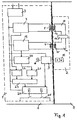
- a safety switch in a first Embodiment a switch unit 1 housed in a housing (for example a power supply connected to a power supply) and one also housed in a housing trigger 2, each on a closable part A or a closing part B are arranged.
- the switch unit 1 is preferably on the closable part A and Trigger 2 arranged on the closing part B.
- the switch unit 1 is powered by an electrical supply source 3 powered and includes a transmission circuit with a clock signal generator 4 for Generation of a clock signal and a transmission coil 5.
- the switch unit 1 further comprises a receiver circuit with a receiver coil 7 and one Hall sensor 9.
- the trigger 2 comprises a magnet 10, which is in the closed position is arranged adjacent to the Hall sensor 9.
- the magnet 10 can be a Be permanent magnet.
- the trigger 2 further comprises a trigger receiver circuit 11 with a trigger coil 12 and a trigger transmission circuit 14 with a coil 15.
- the coils 12 and 15 are arranged so that they in Closed position in each case essentially adjacent to the transmitter coil 5 or Receiver coil 7 lie.
- the trigger receiver circuit 11 is thus over the Trigger coil 12 can be inductively coupled to the transmitter coil 5 of the transmitter circuit, an inductive coupling occurs as soon as transmitter coil 5 and trigger coil 12 are neighboring.
- the trigger send circuit 14 is on the trigger receiver circuit 11 coupled via a modification circuit 17.
- the Hall sensor 9 activated when this is done by the magnet 10 at the location of the Hall sensor 9 generated magnetic field is sufficient to trigger the Hall sensor 9.
- the Hall sensor 9 can be adjusted via a trim resistor 18, so that by Adjusting its switching threshold the distance between switch unit 1 and Trigger 2, in which the Hall sensor 9 triggers, can be set.
- the modification circuit 17 can in particular be a Include frequency divider, which the frequency of the clock signal by one predeterminable factor.
- the trigger transmission circuit 14 thus sends modified clock signal when the trigger receiver circuit 11 has a clock signal received by the broadcasting group.
- the trigger transmission circuit 14 is in turn on the Coil 15 can be inductively coupled to the receiver coil 7 of the receiver circuit, wherein an inductive coupling occurs as soon as the receiver coil 7 and coil 15 are neighboring.
- an inductive coupling occurs as soon as the receiver coil 7 and coil 15 are neighboring.
- the receiver coil 7 thus receives the modified clock signal.
- the Receiver coil 7 is excited with the frequency of the modified clock signal.
- the receiver circuit also contains a bandpass filter 19.
- the bandpass filter 19 is designed so that it is only the one modified by the modifying circuit 17 Passes the clock signal and filters out other external signals. It's about one Amplifier 20 for amplifying the modified clock signal with a pulse shape and Counter stage 21 connected, in which the modified clock signal processed and is added up.
- the clock signal generator 4 is also directly connected to another Pulse shape and count stage 22 connected.
- the pulse shape and counting stage 22 thus receives the unmodified one generated by the clock signal generator 4 Clock signal.
- At the outputs of the pulse shape and counter stages 21, 22 is one common comparator stage 23 connected, its output on a channel a relay stage 24 is performed.
- Another channel of relay stage 24 is with the Hall sensor 9 connected, from Hall sensor 9 an enable signal this channel is supplied when the Hall sensor 9 by approaching the trigger 2 belonging magnet 10 is activated.
- Comparator level 23 evaluates that of the pulse shape and counter stages 21, 22 received counter readings, the Comparator stage 23 by the first incoming signal of counter stage 22 is activated and the pulse shape and counting stages 21, 22 after at least one suitably selected time interval or counter reading.
- the Comparator stage 23 can be designed so that it counts the pulse shape and Counting stages 21, 22 according to suitably chosen, different time intervals or queries, so that the pulse shape and counting stage 21, the modified clock signal with a by a certain factor compared to that of Clock signal generator 4 generated clock signal received lower frequency, first after a time period that is longer by the same factor or by the same time Factor smaller counter reading is queried than the pulse shape and counter stage 22.
- the comparator stage 23 then only outputs an output signal to the relay stage 24 off when the two received counter readings are in a predetermined Stand in relation to each other.
- the counter readings of the pulse form and counter stages 21, 22 can also be queried simultaneously by the relay stage 24, in which case the Comparator stage 23 is designed so that it counts the pulse shape and
- Count stages 21, 22 divided by each other. She only enters then Output signal to the relay stage 24 when the quotient determined Factor of the frequency divider corresponds.
- the pulse shape and counting stages 21, 22 can also be designed so that the different frequency from Clock signal generator 4 generated and modified signal by different Modulation is balanced again.
- the comparator stage 23 then asks Meter readings after the same, suitably selected time periods and only add Match an output signal to relay stage 24.
- the relay stage 24 is connected to an enable path 25.
- the Relay stage 24 is preferably a safety relay stage, which two Safety relay includes.
- the enabling path 25 is switched through via the relay stage 24 only if both channels of relay stage 24 were previously inactive and then a signal is present on both channels of relay stage 24. This sets both ahead that the comparator 23 produces an output signal, as well as that Hall sensor 9 is activated. As a result, the safety switch has one redundant design.
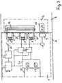
- the transmission circuit comprises Switch unit 1 a switch 26 for closing or interrupting the Transmission circuit that can be switched on via the Hall sensor 9.
- the Trigger 2 to the switch unit 1 is thus the switch 26 via the Hall sensor 9 turned on when the magnet 10 at the location of Hall sensor 9 generated magnetic field is sufficient to trigger the Hall sensor 9.
- the Hall sensor 9 is preferably via a trim resistor 18 adjustable, so that the distance between Switch unit 1 and trigger 2, in which the Hall sensor 9 triggers can be.
- the switch 26 is switched on and thus the broadcasting circuit is closed. Only then is that from Clock signal generator 4 generated clock signal released, whereupon analogous to that in Fig. 1 illustrated embodiment, the transmitter coil 5 due to the inductive Coupling to the trigger receiver circuit 11 induces a voltage in this.
- the trigger 2 and the evaluation unit of the Safety switch constructed exactly as in the first embodiment. 2, however, in the second embodiment, the Clock signal generator 4 does not generate the clock signal continuously, but only at Release by activating the Hall sensor 9 of the pulse shape and counting stage 22 fed. Likewise, the inductive coupling between the transmitter coil 5 of the Transmission circuit and the trigger coil 12 of the trigger receiver circuit 11 only then when transmitter coil 5 and trigger coil 12 are adjacent and the Transmission circuit by activating the Hall sensor 9 by the magnet 10 closed is.
- trigger 2 approaches switch unit 1 and closed transmission circuit is analogous to the first embodiment by the Modifier circuit 17 belonging to trigger 2, modified clock signal of Pulse shape and counter stage 21 supplied.
- the pulse shape and counting stages 21, 22 are analogous to the first embodiment at the common comparator stage 23 connected, the output of which is connected to relay stage 24.
- the one with the Relay stage 24 interconnected release path 25 is only then through the relay mare 24 switched through when the comparator stage 23 released the clock signal and the clock signal modified by the modifying circuit 17 in one receives predetermined frequency ratio. Feeding a shared and a modified signal is redundant because the transmission of only the released signal no loss of information regarding the approximation of the trigger 2 would mean. This embodiment also results thus by the redundant design in relation to the actuation of the Safety switch increased reliability.
- Embodiment 3 is analogous to the second in a third embodiment Embodiment also provided a switch 26 which when the Hall sensor 9 by the magnet 10 that generated by the clock signal generator 4 Clock signal releases.
- the broadcasting circuit comprises analogously to the first two Embodiments of a transmitter coil 5, which here is a magnetizable U-shaped Core 27 has.
- the recipient group comprises two Receiver coils 7, each of which also has a magnetizable U-shaped core 27 and which are each followed by an amplifier stage 20.
- the Outputs of the amplifier stages 20 are each directly with a channel Relay stage 24 connected.
- the trigger 2 includes in addition to the adjacent in the closed position Hall sensor 9 arranged magnets 10 only the trigger coil 12, which in Closed position adjacent to the transmitter coil 5 and the two Receiver coils 7 is arranged.
- the trigger coil 12 also has a U-shaped magnetizable core 27.
Landscapes
- Switches That Are Operated By Magnetic Or Electric Fields (AREA)
- Push-Button Switches (AREA)
- Electronic Switches (AREA)
- Measuring Magnetic Variables (AREA)
- Burglar Alarm Systems (AREA)
Abstract
Description
Claims (24)
- Berührungsloser Sicherheitsschalter zum Feststellen der Schließstellung eines schließenden Teils (B) gegenüber einem verschließbaren Teil (A), mit einer von einer elektrischen Versorgungsquelle (3) stromversorgten Schaltereinheit (1) an einem der Teile und einem an dem anderen Teil angeordneten, einen Magneten (10) umfassenden Auslöser (2), dadurch gekennzeichnet, daß die Schaltereinheit (1) einen Sendekreis mit einem Taktsignalgenerator (4) und einer Sendespule (5), einen mit einer Auswerteeinheit verbundenen Empfängerkreis mit mindestens einer Empfängerspule (7) sowie einen auf den Magneten (10) ansprechenden Hallsensor (9) und der Auslöser (2) eine in Schließstellung von der Sendespule (5) induktiv erregbare und die Empfängerspule (7) erregende Auslöserspule (12) umfaßt, wobei in Schließstellung die Auswerteeinheit nach einem Vergleich der gesendeten und empfangenen Taktsignale einen Freigabepfad (25) ansteuert, wenn der Hallsensor (9) über den Magneten (10) aktiviert ist.
- Sicherheitsschalter nach Anspruch 1, dadurch gekennzeichnet, daß in Schließstellung der Auswerteeinheit zwei Signale zuführbar sind, die den Freigabepfad (25) nur ansteuert, wenn beide Signale in der Auswerteeinheit vorliegen.
- Sicherheitsschalter nach Anspruch 1 oder 2, dadurch gekennzeichnet, daß der Auswerteeinheit eine insbesondere zweikanalige Relaisstufe (24) nachgeschaltet ist, über die der Freigabepfad (25) durchschaltbar ist.
- Sicherheitsschalter nach einem der Ansprüche 1 bis 3, dadurch gekennzeichnet, daß zwei Empfängerspulen (7) vorgesehen sind, die mit der Auslöserspule (12) induktiv koppelbar sind, wobei der Freigabepfad (25) nur dann durchschaltbar ist, wenn von beiden Empfängerspulen (7) jeweils ein Signal geliefert wird und zuvor kein Signal vorlag.
- Sicherheitsschalter nach einem der Ansprüche 1 bis 4, dadurch gekennzeichnet, daß ein über den Hallsensor (9) betätigbarer Schalter (26) im Sendekreis vorgesehen ist, wobei das von dem Taktsignalgenerator (4) erzeugte Taktsignal über den Hallsensor (9) an die Empfängerspule (7) freigebbar ist.
- Sicherheitsschalter nach einem der Ansprüche 1 bis 5, dadurch gekennzeichnet, daß der Sendekreis mit der Auswerteeinheit verbunden ist.
- Sicherheitsschalter nach einem der Ansprüche 1 bis 6, dadurch gekennzeichnet, daß die Empfängerspule (7) mit der Auslöserspule (12) indirekt induktiv koppelbar ist, wobei der Auslöser (2) einen die Auslöserspule (12) umfassenden Auslöserempfängerkreis (11) und einen an diesen gekoppelten, mit der Empfängerspule induktiv koppelbaren Auslösersendekreis (14) umfaßt.
- Sicherheitsschalter nach Anspruch 7, dadurch gekennzeichnet, daß der Auslösersendekreis (14) über einen Modifizierkreis (17) mit dem Auslöserempfängerkreis (11) derart gekoppelt ist, daß der Auslösersendekreis (14) ein modifiziertes Taktsignal aussendet.
- Sicherheitsschalter nach Anspruch 8, dadurch gekennzeichnet, daß ein durch den Taktsignalgenerator (4) erzeugtes Taktsignal und das vom Empfängerkreis empfangene modifizierte Taktsignal der Auswerteeinheit zuführbar sind, die den Freigabepfad (25) ansteuert, wenn die beiden Taktsignale in einem vorbestimmten Frequenzverhältnis stehen.
- Sicherheitsschalter nach Anspruch 8 oder 9, dadurch gekennzeichnet, daß die Auswerteeinheit zwei parallel geschaltete Impulsform- und Zählstufen (21, 22) umfaßt, von denen eine zur Aufbereitung und Addition des durch den Taktsignalgenerator (4) erzeugten Taktsignals und eine zur Aufbereitung und Addition des modifizierten Taktsignals ausgelegt ist.
- Sicherheitsschalter nach Anspruch 10, dadurch gekennzeichnet, daß die Auswerteeinheit eine Vergleicherstufe (23) umfaßt, die den Impulsform- und Zählstufen (21, 22) nachgeschaltet ist und nur ein Ausgangssignal abgibt, wenn die Zählerstände der Impulsform- und Zählstufen (21, 22) in einem vorbestimmten Frequenzverhältnis stehen.
- Sicherheitsschalter nach Anspruch 11, dadurch gekennzeichnet, daß ein über den Hallsensor (9) freigebbares Signal der Relaisstufe (24) über einen Kanal und das Ausgangssignal der Vergleicherstufe (23) der Relaisstufe (24) über einen anderen Kanal zuführbar ist, wobei der Freigabepfad (25) nur dann durch die Relaisstufe (24) durchschaltbar ist, wenn an beiden Kanälen ein Signal vorliegt und zuvor an beiden Kanälen kein Signal vorlag.
- Sicherheitsschalter nach einem der Ansprüche 5 bis 11, dadurch gekennzeichnet, daß das von dem Taktsignalgenerator (4) erzeugte Taktsignal, das über den Hallsensor (9) freigebbar ist, über einen Eingang der Relaisstufe (24) zuführbar ist, und das vom Empfängerkreis empfangene, modifizierte Taktsignal der Relaisstufe (24) über einen anderen Kanal zuführbar ist, wobei der Freigabepfad (25) nur dann durch die Relaisstufe (24) durchschaltbar ist, wenn jeweils an beiden Kanälen ein Signal vorliegt und zuvor an beiden Kanälen kein Signal vorlag.
- Sicherheitsschalter nach einem der Ansprüche 11 bis 13, dadurch gekennzeichnet, daß die Vergleicherstufe (23) so ausgelegt ist, daß sie jeweils nach einem geeignet gewählten, konstanten Zeitintervall die Zählerstände der Impulsform- und Zählstufen (21, 22) abfragt.
- Sicherheitsschalter nach Anspruch 14, dadurch gekennzeichnet, daß die Vergleicherstufe (23) so ausgelegt ist, daß sie ein Ausgabesignal an die Relaisstufe (24) nur ausgibt, wenn die Zählerstände der Impulsform- und Zählstufen (21, 22) sich um einen vorgegebenen Wert unterscheiden.
- Sicherheitsschalter nach einem der Ansprüche 8 bis 15, dadurch gekennzeichnet, daß der Modifizierkreis (17) ein Frequenzteiler ist, welcher ein vom Auslöserempfängerkreis (11) empfangenes Taktsignal um einen vorbestimmten Faktor herunterteilt.
- Sicherheitsschalter nach Anspruch 16, dadurch gekennzeichnet, daß die Impulsform- und Zählstufe (21) erst nach einem um den Faktor des Modifizierkreises (17) längeren Zeitintervall als die Impulsform- und Zählstufe (22) abgefragt wird und die Vergleicherstufe (23) nur ein Ausgangssignal an die Relaisstufe (24) ausgibt, wenn die beiden empfangenen Zählerstände gleich sind.
- Sicherheitsschalter nach Anspruch 16, dadurch gekennzeichnet, daß die Impulsform- und Zählstufen (21, 22) so ausgelegt sind, daß sie die unterschiedliche Frequenz von freigegebenem und modifiziertem Signal durch unterschiedliche Modulation wieder ausgleichen.
- Sicherheitsschalter nach einem der Ansprüche 8 bis 18, dadurch gekennzeichnet, daß der Modifizierkreis (17) so ausgelegt ist, daß die Frequenzdifferenz zwischen dem vom Taktsignalgenerator (4) erzeugten und dem modifizierten Taktsignal relativ zur Frequenz des vom Taktsignalgenerator (4) erzeugten Taktsignals groß ist.
- Sicherheitsschalter nach einem der Ansprüche 1 bis 19, dadurch gekennzeichnet, daß der Empfängerspule (7) ein Bandpassfilter (19) nachgeschaltet ist, welcher nur das gegebenenfalls modifizierte Taktsignal durchläßt.
- Sicherheitsschalter nach einem der Ansprüche 1 bis 20, dadurch gekennzeichnet, daß der Auswerteeinheit mindestens ein Verstärker (20) vorgeschaltet ist.
- Sicherheitsschalter nach einem der Ansprüche 1 bis 21, dadurch gekennzeichnet, daß der Hallsensor (9) abgleichbar ist.
- Sicherheitsschalter nach einem der Ansprüche 1 bis 22, dadurch gekennzeichnet, daß der Magnet (10) ein Permanentmagnet ist.
- Sicherheitsschalter nach einem der Ansprüche 1 bis 23, dadurch gekennzeichnet, daß die Schaltereinheit (1) an dem verschließbaren Teil (A) und der Auslöser (2) an dem schließenden Teil (B) angeordnet ist.
Applications Claiming Priority (3)
| Application Number | Priority Date | Filing Date | Title |
|---|---|---|---|
| DE19840620 | 1998-09-05 | ||
| DE19840620A DE19840620C1 (de) | 1998-09-05 | 1998-09-05 | Berührungsloser Sicherheitsschalter |
| US09/388,683 US6212052B1 (en) | 1998-09-05 | 1999-09-02 | Contactless safety switch |
Publications (3)
| Publication Number | Publication Date |
|---|---|
| EP0986176A2 true EP0986176A2 (de) | 2000-03-15 |
| EP0986176A3 EP0986176A3 (de) | 2001-08-01 |
| EP0986176B1 EP0986176B1 (de) | 2004-02-25 |
Family
ID=26048665
Family Applications (1)
| Application Number | Title | Priority Date | Filing Date |
|---|---|---|---|
| EP99116557A Expired - Lifetime EP0986176B1 (de) | 1998-09-05 | 1999-08-24 | Berührungsloser Sicherheitsschalter |
Country Status (6)
| Country | Link |
|---|---|
| US (1) | US6212052B1 (de) |
| EP (1) | EP0986176B1 (de) |
| JP (1) | JP2000106071A (de) |
| CN (1) | CN1139959C (de) |
| BR (1) | BR9904153A (de) |
| DE (1) | DE19840620C1 (de) |
Cited By (3)
| Publication number | Priority date | Publication date | Assignee | Title |
|---|---|---|---|---|
| WO2018019684A1 (de) * | 2016-07-29 | 2018-02-01 | Phoenix Contact Gmbh & Co.Kg | Verfahren zum signalisieren der position einer sicherheitseinrichtung und sicherheitsschaltsystem |
| CN108931182A (zh) * | 2017-05-26 | 2018-12-04 | 黑拉有限责任两合公司 | 用于机动车的传感器 |
| US10989883B2 (en) | 2017-05-03 | 2021-04-27 | Trumpf Schweiz Ag | Connector arrangements and methods of monitoring connector arrangements |
Families Citing this family (37)
| Publication number | Priority date | Publication date | Assignee | Title |
|---|---|---|---|---|
| DE19928641C1 (de) * | 1999-06-23 | 2001-05-03 | Schmersal K A Gmbh & Co | Sicherheitssensor |
| DE19953898C5 (de) * | 1999-11-10 | 2004-07-01 | K.A. Schmersal Gmbh & Co | Zugangsschutzeinrichtung |
| US7086111B2 (en) * | 2001-03-16 | 2006-08-08 | Braun Gmbh | Electric dental cleaning device |
| DE10159395B4 (de) * | 2001-12-04 | 2010-11-11 | Braun Gmbh | Vorrichtung zur Zahnreinigung |
| DK1367958T3 (da) * | 2001-03-14 | 2008-01-28 | Braun Gmbh | Anordning til tandrensning |
| US6591523B2 (en) | 2001-03-27 | 2003-07-15 | Apple Corporate Technologies, Inc. | Acoustic card |
| US6675511B2 (en) | 2001-04-20 | 2004-01-13 | Apple Corporate Technologies, Inc. | Acoustic card |
| US6501040B2 (en) | 2001-05-18 | 2002-12-31 | Honeywell International Inc. | Dual directional cable actuated emergency stop device |
| US8443476B2 (en) | 2001-12-04 | 2013-05-21 | Braun Gmbh | Dental cleaning device |
| DE10216225A1 (de) * | 2002-04-08 | 2003-10-30 | Euchner Gmbh & Co | Elektromagnetisches Zuhaltesystem eines Sicherheitsschalters |
| DE102004062150A1 (de) * | 2004-12-23 | 2006-07-13 | Braun Gmbh | Auswechselbares Zubehörteil für ein Elektrokleingerät und Verfahren zum Bestimmen der Benutzungsdauer des Zubehörteils |
| DE102007022827A1 (de) * | 2007-05-15 | 2008-11-20 | Braun Gmbh | Zahnbürstenaufsatzteil sowie Verfahren zu seiner Herstellung |
| GB0801706D0 (en) * | 2008-01-31 | 2008-03-05 | Eja Ltd | Safety switch |
| US8779778B2 (en) | 2009-04-28 | 2014-07-15 | Omron Corporation | Proximity switch |
| GB2470775B (en) * | 2009-06-05 | 2015-06-24 | Mechan Controls Ltd | Safety switching device |
| US8456792B2 (en) * | 2010-02-05 | 2013-06-04 | Honeywell International Inc. | Secure non-contact switch |
| US8699200B2 (en) * | 2010-02-05 | 2014-04-15 | Honeywell International Inc. | Secure non-contact switch |
| TWI545895B (zh) * | 2010-03-10 | 2016-08-11 | 旺玖科技股份有限公司 | 無接觸式開關及其控制方法 |
| EP2420203B1 (de) | 2010-08-19 | 2019-10-23 | Braun GmbH | Resonanzmotoreinheit und Elektrogerät mit Resonanzmotoreinheit |
| US9214274B2 (en) * | 2010-10-04 | 2015-12-15 | Dr. Hahn Gmbh & Co. Kg | Method and apparatus for transmitting signals between a wall and a leaf fastened to this wall using hinges around a hinge axis |
| CN103703668B (zh) | 2011-07-25 | 2016-12-07 | 博朗有限公司 | 线性电动聚合物马达和具有所述线性电动聚合物马达的装置 |
| EP2550938B1 (de) | 2011-07-25 | 2015-01-14 | Braun GmbH | Mundpflegevorrichtung |
| EP2550937B1 (de) | 2011-07-25 | 2014-02-26 | Braun GmbH | Magnetische Verbindung zwischen einem Zahnbürstengriff und einem Bürstenkopf |
| DE102012107717B3 (de) * | 2012-08-22 | 2013-09-12 | Bernstein Ag | Berührungslos arbeitender Sicherheitsschalter |
| DE102012107715B3 (de) * | 2012-08-22 | 2013-09-12 | Bernstein Ag | Berührungslos arbeitender Sicherheitsschalter |
| DE102012107716B3 (de) * | 2012-08-22 | 2013-09-26 | Bernstein Ag | Berührungslos arbeitender Sicherheitsschalter |
| CN104067365B (zh) * | 2012-11-21 | 2017-03-01 | 松下知识产权经营株式会社 | 无触点开关装置 |
| CN105210124A (zh) * | 2013-03-12 | 2015-12-30 | 消防和安全硬件私人有限公司 | 位置监测装置 |
| US8946653B2 (en) * | 2013-03-14 | 2015-02-03 | Teleflex Medical Incorporated | UV-C catheter hub sterilization and data acquisition system |
| CN107000974B (zh) * | 2014-11-27 | 2019-05-07 | 三菱电机株式会社 | 电梯的位置检测装置 |
| WO2017201190A1 (en) | 2016-05-18 | 2017-11-23 | Shanghai Yanfeng Jinqiao Automotive Trim Systems Co. Ltd | Console assembly for vehicle interior |
| US11572723B2 (en) | 2019-02-27 | 2023-02-07 | Shanghai Yanfeng Jinqiao Automotive Triim Systems Co. Ltd. | Vehicle interior component |
| EP3822031A1 (de) * | 2019-11-14 | 2021-05-19 | Hilti Aktiengesellschaft | Verfahren zum steuern und regeln einer werkzeugmaschine |
| EP3822033A1 (de) | 2019-11-14 | 2021-05-19 | Hilti Aktiengesellschaft | Verfahren zum steuern und regeln einer werkzeugmaschine |
| CN111104121B (zh) * | 2019-12-20 | 2023-05-16 | 抖音视界有限公司 | 检测方法、装置、设备和存储介质 |
| DE102023113058A1 (de) | 2023-05-17 | 2024-11-21 | Multivac Sepp Haggenmüller Se & Co. Kg | Schutzschalter für eine Maschine |
| CN117444760A (zh) * | 2023-11-08 | 2024-01-26 | 泽木焱光学科技(苏州)有限公司 | 一种非球面抛光机器人安全隔离罩 |
Family Cites Families (10)
| Publication number | Priority date | Publication date | Assignee | Title |
|---|---|---|---|---|
| DE2033682A1 (de) * | 1970-07-07 | 1972-01-27 | Budapesti Radiotechnikai Gyar | Anschlußvornchtung fur elektrische Gerate |
| DE3029543C2 (de) * | 1980-08-04 | 1982-08-05 | Hermann Dipl.-Ing. 8000 München Zierhut | Kontaktloser induktiver Übertrager |
| DE3236224C2 (de) * | 1982-09-30 | 1985-03-28 | Werner Turck Gmbh & Co Kg, 5884 Halver | Induktiver Annäherungsschalter |
| DE3546245C3 (de) * | 1985-12-28 | 1994-11-17 | Link Walter | Berührungsloser Näherungsschalter |
| DE3616389A1 (de) * | 1986-05-15 | 1987-11-19 | Turck Werner Kg | Beruehrungslos wirkender naeherungsschalter |
| AU5420790A (en) * | 1989-04-14 | 1990-11-16 | Eja Engineering Company Limited | Safety switch assembly |
| DE4112064A1 (de) * | 1990-04-12 | 1991-10-17 | Hirschmann Richard Gmbh Co | Alarmgeberanordnung |
| DE4113665C2 (de) * | 1991-04-26 | 1994-08-04 | Binsack Reedtechnik Gmbh | Fremdfeldsichere Kontaktanordnung für magnetisch betätigte Näherungsschalter |
| JP3363341B2 (ja) * | 1997-03-26 | 2003-01-08 | 松下電工株式会社 | 非接触電力伝達装置 |
| JP3247328B2 (ja) * | 1997-12-09 | 2002-01-15 | 浩 坂本 | 非接触電力伝達装置 |
-
1998
- 1998-09-05 DE DE19840620A patent/DE19840620C1/de not_active Expired - Fee Related
-
1999
- 1999-08-24 EP EP99116557A patent/EP0986176B1/de not_active Expired - Lifetime
- 1999-08-31 CN CNB991181891A patent/CN1139959C/zh not_active Expired - Fee Related
- 1999-09-02 US US09/388,683 patent/US6212052B1/en not_active Expired - Lifetime
- 1999-09-03 BR BR9904153-7A patent/BR9904153A/pt not_active IP Right Cessation
- 1999-09-03 JP JP11250479A patent/JP2000106071A/ja active Pending
Cited By (4)
| Publication number | Priority date | Publication date | Assignee | Title |
|---|---|---|---|---|
| WO2018019684A1 (de) * | 2016-07-29 | 2018-02-01 | Phoenix Contact Gmbh & Co.Kg | Verfahren zum signalisieren der position einer sicherheitseinrichtung und sicherheitsschaltsystem |
| US10928003B2 (en) | 2016-07-29 | 2021-02-23 | Phoenix Contact Gmbh & Co. Kg | Method for signaling the position of a safety device, and safety switching system |
| US10989883B2 (en) | 2017-05-03 | 2021-04-27 | Trumpf Schweiz Ag | Connector arrangements and methods of monitoring connector arrangements |
| CN108931182A (zh) * | 2017-05-26 | 2018-12-04 | 黑拉有限责任两合公司 | 用于机动车的传感器 |
Also Published As
| Publication number | Publication date |
|---|---|
| BR9904153A (pt) | 2000-09-26 |
| EP0986176A3 (de) | 2001-08-01 |
| US6212052B1 (en) | 2001-04-03 |
| CN1139959C (zh) | 2004-02-25 |
| CN1247374A (zh) | 2000-03-15 |
| EP0986176B1 (de) | 2004-02-25 |
| JP2000106071A (ja) | 2000-04-11 |
| DE19840620C1 (de) | 2000-04-27 |
Similar Documents
| Publication | Publication Date | Title |
|---|---|---|
| EP0986176B1 (de) | Berührungsloser Sicherheitsschalter | |
| EP0968567B2 (de) | Sicherheitsschalter | |
| DE3881637T2 (de) | Übertragungsvorrichtung für elektrische Energie. | |
| EP0072016B1 (de) | Das Spiel zwischen der Scherstange und den relativ zu dieser bewegbaren Schneidelementen einer Schneideinrichtung Überwachende Einrichtung | |
| EP0527719B1 (de) | Fernbedienungseinrichtung | |
| WO1989002648A1 (fr) | Procede et dispositif de detection des temps de commutation d'electro-vannes | |
| WO2003069538A1 (de) | Mit einem transponder betätigbare schaltvorrichtung | |
| DE3149789C1 (de) | Vorrichtung zur induktiven Identifizierung einer Information | |
| DE2455923A1 (de) | Luftdruckueberwachungsvorrichtung fuer fahrzeugreifen | |
| DE2538238A1 (de) | Anordnung zum steuern der signalanlagen von strassenkreuzungen | |
| EP0418989A2 (de) | Lichtschranke | |
| EP1808879A1 (de) | System zur kontaktlosen Zustandserkennung | |
| EP0316872B1 (de) | Alarmgebeanordnung | |
| DE69926455T2 (de) | Schlüsselsicherheitsschalter | |
| DE3210985A1 (de) | Beruehrungslose elektronische steuerung fuer eine sanitaere armatur, insbesondere ein urinal | |
| DE69904428T2 (de) | Vorrichtung zur erfassung der anwesenheit eines menschlichen körpers | |
| DE102005009489A1 (de) | Elektronikbaugruppe für eine Positionserfassungseinrichtung mit einer Weckvorrichtung zum Verarbeiten eines Aufweck-Strompulses einer Wiegand-Spule | |
| EP0348818A2 (de) | Schaltungsanordnung zur Übertragung mindestens eines veränderlichen Messwertes von jeweils einem der Räder eines Fahrzeuges zu einer zentralen Überwachungseinheit | |
| DE10333537A1 (de) | Schutzschalter mit einem elektronischen programmierbaren System | |
| DE2452732C3 (de) | Vorrichtung zum Ermitteln, ob ein als Meßwertgeber vorgesehener Schalter sich in geöffnetem oder geschlossenem Zustand befindet | |
| DE102012005371A1 (de) | Steuervorrichtung eines Bedienelements in einem Kraftfahrzeug | |
| DE69226803T2 (de) | Positionsmeldevorrichtung eines beweglichen Gliedes | |
| EP0602324A1 (de) | Einbruchmelderanordnung | |
| DE2249408A1 (de) | Sicherheitseinrichtung | |
| DE69923909T2 (de) | Verfahren und Vorrichtung zur Steuerung einer oder mehrerer Geräte, insbesondere einer in zwei Richtungen drehbaren Rolladenwalze |
Legal Events
| Date | Code | Title | Description |
|---|---|---|---|
| PUAI | Public reference made under article 153(3) epc to a published international application that has entered the european phase |
Free format text: ORIGINAL CODE: 0009012 |
|
| AK | Designated contracting states |
Kind code of ref document: A2 Designated state(s): CH DE FR GB IT LI SE |
|
| AX | Request for extension of the european patent |
Free format text: AL;LT;LV;MK;RO;SI |
|
| PUAL | Search report despatched |
Free format text: ORIGINAL CODE: 0009013 |
|
| AK | Designated contracting states |
Kind code of ref document: A3 Designated state(s): AT BE CH CY DE DK ES FI FR GB GR IE IT LI LU MC NL PT SE |
|
| AX | Request for extension of the european patent |
Free format text: AL;LT;LV;MK;RO;SI |
|
| RIC1 | Information provided on ipc code assigned before grant |
Free format text: 7H 03K 17/97 A, 7G 08B 13/08 B, 7G 08B 13/24 B |
|
| 17P | Request for examination filed |
Effective date: 20010906 |
|
| AKX | Designation fees paid |
Free format text: CH DE FR GB IT LI SE |
|
| GRAP | Despatch of communication of intention to grant a patent |
Free format text: ORIGINAL CODE: EPIDOSNIGR1 |
|
| GRAS | Grant fee paid |
Free format text: ORIGINAL CODE: EPIDOSNIGR3 |
|
| GRAA | (expected) grant |
Free format text: ORIGINAL CODE: 0009210 |
|
| AK | Designated contracting states |
Kind code of ref document: B1 Designated state(s): CH DE FR GB IT LI SE |
|
| REG | Reference to a national code |
Ref country code: GB Ref legal event code: FG4D Free format text: NOT ENGLISH |
|
| REG | Reference to a national code |
Ref country code: CH Ref legal event code: EP |
|
| REG | Reference to a national code |
Ref country code: CH Ref legal event code: NV Representative=s name: ICB INGENIEURS CONSEILS EN BREVETS SA |
|
| REF | Corresponds to: |
Ref document number: 59908625 Country of ref document: DE Date of ref document: 20040401 Kind code of ref document: P |
|
| REG | Reference to a national code |
Ref country code: SE Ref legal event code: TRGR |
|
| GBT | Gb: translation of ep patent filed (gb section 77(6)(a)/1977) |
Effective date: 20040520 |
|
| ET | Fr: translation filed | ||
| PLBE | No opposition filed within time limit |
Free format text: ORIGINAL CODE: 0009261 |
|
| STAA | Information on the status of an ep patent application or granted ep patent |
Free format text: STATUS: NO OPPOSITION FILED WITHIN TIME LIMIT |
|
| 26N | No opposition filed |
Effective date: 20041126 |
|
| PGFP | Annual fee paid to national office [announced via postgrant information from national office to epo] |
Ref country code: CH Payment date: 20060815 Year of fee payment: 8 |
|
| PGFP | Annual fee paid to national office [announced via postgrant information from national office to epo] |
Ref country code: FR Payment date: 20060817 Year of fee payment: 8 |
|
| PGFP | Annual fee paid to national office [announced via postgrant information from national office to epo] |
Ref country code: GB Payment date: 20060824 Year of fee payment: 8 |
|
| PGFP | Annual fee paid to national office [announced via postgrant information from national office to epo] |
Ref country code: IT Payment date: 20060831 Year of fee payment: 8 |
|
| PGFP | Annual fee paid to national office [announced via postgrant information from national office to epo] |
Ref country code: SE Payment date: 20060814 Year of fee payment: 8 |
|
| EUG | Se: european patent has lapsed | ||
| REG | Reference to a national code |
Ref country code: CH Ref legal event code: PL |
|
| GBPC | Gb: european patent ceased through non-payment of renewal fee |
Effective date: 20070824 |
|
| PG25 | Lapsed in a contracting state [announced via postgrant information from national office to epo] |
Ref country code: SE Free format text: LAPSE BECAUSE OF NON-PAYMENT OF DUE FEES Effective date: 20070825 Ref country code: LI Free format text: LAPSE BECAUSE OF NON-PAYMENT OF DUE FEES Effective date: 20070831 Ref country code: CH Free format text: LAPSE BECAUSE OF NON-PAYMENT OF DUE FEES Effective date: 20070831 |
|
| REG | Reference to a national code |
Ref country code: FR Ref legal event code: ST Effective date: 20080430 |
|
| PG25 | Lapsed in a contracting state [announced via postgrant information from national office to epo] |
Ref country code: FR Free format text: LAPSE BECAUSE OF NON-PAYMENT OF DUE FEES Effective date: 20070831 |
|
| PG25 | Lapsed in a contracting state [announced via postgrant information from national office to epo] |
Ref country code: GB Free format text: LAPSE BECAUSE OF NON-PAYMENT OF DUE FEES Effective date: 20070824 |
|
| PG25 | Lapsed in a contracting state [announced via postgrant information from national office to epo] |
Ref country code: IT Free format text: LAPSE BECAUSE OF NON-PAYMENT OF DUE FEES Effective date: 20070824 |
|
| PGFP | Annual fee paid to national office [announced via postgrant information from national office to epo] |
Ref country code: DE Payment date: 20091026 Year of fee payment: 11 |
|
| REG | Reference to a national code |
Ref country code: DE Ref legal event code: R119 Ref document number: 59908625 Country of ref document: DE Effective date: 20110301 |
|
| PG25 | Lapsed in a contracting state [announced via postgrant information from national office to epo] |
Ref country code: DE Free format text: LAPSE BECAUSE OF NON-PAYMENT OF DUE FEES Effective date: 20110301 |