EP0986182A2 - Kodierungsapparat und verfahren, dekodierungsapparat und verfahren sowie erzeugungsmedium - Google Patents
Kodierungsapparat und verfahren, dekodierungsapparat und verfahren sowie erzeugungsmedium Download PDFInfo
- Publication number
- EP0986182A2 EP0986182A2 EP99307013A EP99307013A EP0986182A2 EP 0986182 A2 EP0986182 A2 EP 0986182A2 EP 99307013 A EP99307013 A EP 99307013A EP 99307013 A EP99307013 A EP 99307013A EP 0986182 A2 EP0986182 A2 EP 0986182A2
- Authority
- EP
- European Patent Office
- Prior art keywords
- replacement
- data
- input data
- encoding
- randomization
- Prior art date
- Legal status (The legal status is an assumption and is not a legal conclusion. Google has not performed a legal analysis and makes no representation as to the accuracy of the status listed.)
- Withdrawn
Links
Images


Classifications
-
- H—ELECTRICITY
- H03—ELECTRONIC CIRCUITRY
- H03M—CODING; DECODING; CODE CONVERSION IN GENERAL
- H03M13/00—Coding, decoding or code conversion, for error detection or error correction; Coding theory basic assumptions; Coding bounds; Error probability evaluation methods; Channel models; Simulation or testing of codes
- H03M13/27—Coding, decoding or code conversion, for error detection or error correction; Coding theory basic assumptions; Coding bounds; Error probability evaluation methods; Channel models; Simulation or testing of codes using interleaving techniques
- H03M13/2735—Interleaver using powers of a primitive element, e.g. Galois field [GF] interleaver
-
- H—ELECTRICITY
- H03—ELECTRONIC CIRCUITRY
- H03M—CODING; DECODING; CODE CONVERSION IN GENERAL
- H03M13/00—Coding, decoding or code conversion, for error detection or error correction; Coding theory basic assumptions; Coding bounds; Error probability evaluation methods; Channel models; Simulation or testing of codes
- H03M13/29—Coding, decoding or code conversion, for error detection or error correction; Coding theory basic assumptions; Coding bounds; Error probability evaluation methods; Channel models; Simulation or testing of codes combining two or more codes or code structures, e.g. product codes, generalised product codes, concatenated codes, inner and outer codes
- H03M13/2957—Turbo codes and decoding
- H03M13/296—Particular turbo code structure
Definitions
- the present invention relates to an encoding apparatus and method, a decoding apparatus and method, and a providing medium, and particularly to an encoding apparatus and method, a decoding apparatus and method, and a providing medium which are suitably applied when encoding or decoding of, for example, a turbo code is performed.
- a turbo code is known as a code showing performance close to Shannon limit as a theoretical limit of code performance.
- encoding is performed through a structure in which a plurality of convolution encoding circuits and interleavers (interleave circuits) are combined, and at a decoding side, exchange of information concerning input data is made among a plurality of decoding circuits outputting soft outputs, so that a final decoding result is obtained.
- Fig. 1 shows a structure of a conventional turbo encoding apparatus 10.
- This turbo encoding apparatus 10 includes a convolution encoding circuit 1-1 for performing convolution encoding with respect to input data to obtain encoded data, interleavers 2-1 to 2-(N-1) for sequentially interleaving the input data (hereinafter, in the case where it is not necessary to distinguish the interleavers 2-1 to 2-(N-1) individually, each is merely referred to as an interleaver 2. It is the same with other devices.), and convolution encoding circuits 1-2 to 1-N for performing convolution encoding with respect to the output data of the interleavers 2 respectively to obtain encoded data.
- convolution encoding circuits 1-2 to 1-N for performing convolution encoding with respect to the output data of the interleavers 2 respectively to obtain encoded data.
- the convolution encoding circuits 1 perform convolution encoding operations with respect to inputted data, and output the operation results respectively as encoded data.
- the interleavers 2 alter the sequence of inputted data and output them.
- Fig. 2 shows an example of the convolution encoding circuit 1.
- the convolution encoding circuit shown in Fig. 2 is a feedback type convolution encoding circuit with a constraint length of three.
- This convolution encoding circuit 1 includes a termination circuit 21, three exclusive OR circuits (hereinafter referred to as "EXOR circuit") 22-1 to 22-3, and two shift registers 23-1 and 23-2, and generates encoded data from input data.
- EXOR circuit three exclusive OR circuits
- the shift register 23 functions as a delay element for delaying inputted data by one unit time
- the EXOR circuit 22 outputs exclusive OR of inputted data.
- the termination circuit 21 outputs the input data until all of the input data are encoded, and outputs feedback data for only a two-unit time (time corresponding to the number of the shift registers) from the point of time when encoding is completed.
- a process after all the input data are encoded is called a termination in which all the contents of the shift registers 23 are returned to zero, and the decoding side performs decoding on the assumption of this process.
- Fig. 3 shows an example of the interleaver 2.
- the input data inputted to the interleaver 2 are temporarily stored in an input data holding memory 31, and then, sequence is rearranged by a data replacement circuit 32.
- the rearrangement of the sequence of the data is performed on the basis of the contents (replacement position information) of a replacement data ROM (Read Only Memory) 34.
- the data in which the sequence is rearranged are stored in an output data holding memory 33, and then, are outputted as output data.
- Fig. 3 shows an example of an operation of the interleaver 2 in the case where the size of the interleaver 2 is five and the contents of the replacement data ROM 34 are as shown in Fig. 4. That is, when the input data are "11010", in accordance with the data stored in the replacement data ROM 34, the data replacement circuit 32 performs a replacement process of the input data, so that "00111" are outputted as output data.
- the operation of the turbo encoding apparatus 10 shown in Fig. 1 will be described.
- the input data are supplied to the convolution encoding circuit 1-1.
- this convolution encoding circuit 1-1 a convolution encoding operation is performed to the input data, and the termination is subsequently performed, so that encoded data through the encoding process including the termination are outputted.
- the input data are supplied to the series circuit of the interleavers 2-1 to 2-(N-1), and the sequence of the inputted data is sequentially altered and the data are outputted.
- the output data of the interleavers 2-1 to 2-(N-1) are supplied to the corresponding convolution encoding circuits 1-2 to 1-N, respectively.
- the convolution encoding operation is performed to the output data of the corresponding interleavers 2-1 to 2-(N-1) respectively, and the termination is subsequently performed, so that encoded data through the encoding process including the termination are outputted.
- Fig. 5 shows the relation between the number of bits of input data and that of encoded data in the turbo encoding apparatus 10.
- Fig. 6 shows a structure of a conventional turbo decoding apparatus 40.
- This turbo decoding apparatus 40 includes a plurality of soft output decoding circuits 51-1 to 51-N corresponding to the number of encoded data (reception data) outputted from the turbo encoding apparatus 10.
- the soft output decoding circuits 51-1 to 51-N are structured by using a so-called soft output decoding system having a function to calculate a probability that the input data at the encoding side is 0 or 1, such as a MAP (Maximum Aposteriori Probability) decoder and a SOVA (Soft Output Viterbi Algorithm) decoder.
- MAP Maximum Aposteriori Probability
- SOVA Soft Output Viterbi Algorithm
- the operation of the turbo decoding apparatus 40 shown in Fig. 6 will be described.
- the reception data (encoded data) are supplied to the soft output decoding circuits 51-1 to 51-N, respectively.
- the respective decoding circuits 51-1 to 51-N mutually use estimation probability value data with respect to the input data except the termination bit at the encoding side, and several to several tens repetitive decoding operations are performed.
- Final decoded data are outputted from an arbitrary decoding circuit (in Fig. 6, the decoding circuit 51-1).
- Fig. 7 shows the relation among the number of bits of the reception data of the turbo decoding apparatus 40, that of the estimation probability value data, and that of the decoded data, and corresponds to the relation of the respective numbers of bits in the turbo encoding apparatus 10 in Fig. 1.
- the soft output decoding circuits 51-1 to 51-N calculate k-bit estimation probability value data of the input data except the termination bit from the (n 1 + t 1 ) to (n m + t m )-bit reception data.
- the k-bit estimation probability value data are exchanged among the respective decoding circuits, and k-bit decoded data are finally outputted.
- the interleaver 2 satisfies the following two conditions at the same time.
- the foregoing two conditions relate to performance index values defined for an error correction code, which are called a minimum distance of a code and a multiplicity of a minimum distance code. These two conditions are necessitated in order for the error correction code to show excellent performance.
- the condition 1 corresponds to that the minimum distance becomes large, and the condition 2 corresponds to that the multiplicity of the minimum distance code becomes small.
- affine interleaver Other than the interleaver to determine a replacement position by using random numbers, there is an affine interleaver. Although this affine interleaver is suitable as an interleaver satisfying the condition 1, it can not satisfy the condition 2.
- the present invention has been made in view of such circumstances, and an object of the invention is to provide, in at least preferred embodiments, an interleaver satisfying the foregoing condition 1 and the condition 2 at the same time.
- An encoding apparatus, an encoding method, and a providing medium of the invention are characterized in that interleave means replaces the input data by using an interleaver in which the sum of distances between arbitrary two points before and after replacement is a predetermined value or more, and further randomizes the replaced input data.
- a decoding apparatus, a decoding method, and a providing medium are characterized by performing a deinterleave process opposite to an interleave process performed by the encoding apparatus.
- Fig. 1 is a block diagram showing a structure of an example of a conventional turbo encoding apparatus.
- Fig. 2 is a block diagram showing a structure of a convolution encoding circuit.
- Fig. 3 is a block diagram showing a structure of an interleaver.
- Fig. 4 is a view for explaining data stored in a replacement ROM.
- Fig. 5 is a view showing the relation between the number of bits of input data and that of encoded data in a turbo encoding apparatus.
- Fig. 6 is a block diagram showing a structure of a turbo decoding apparatus.
- Fig. 7 is a view showing the relation between the number of bits of reception data, that of estimation probability value data, and that of decoded data in the turbo decoding apparatus.
- Fig. 8 is a block diagram showing a structure of an embodiment of a turbo encoding apparatus to which an embodiment of the present invention is applied.
- Fig. 9 is a block diagram showing a structure of an interleaver.
- Fig. 10 is a flowchart for explaining a process of determining replacement positions.
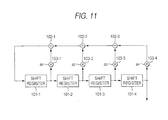
- Fig. 11 is a block diagram showing a structure of an M-sequence generating circuit.
- Fig. 12 is a flowchart for explaining another process of determining replacement positions.
- Fig. 13 is a flowchart for explaining still another process of determining replacement positions.
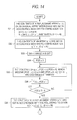
- Fig. 14 is a flowchart for explaining still another process of determining replacement positions.
- Fig. 15 is a flowchart subsequent to Fig. 14
- Fig. 16 is a block diagram showing a structure of a turbo decoding apparatus.
- Interleave means for example, an interleaver 71 of Fig. 8 of an encoding apparatus of the invention is characterized by comprising replacement means (for example, step S1 of Fig. 10) for replacing input data by using an interleaver in which the sum of distances between arbitrary two points before and after replacement is a predetermined value or more, and randomization means (for example, step S4 of Fig. 10) for randomizing the input data replaced by the replacement means.
- a decoding apparatus of the invention is characterized by comprising deinterleave means (for example, a soft output decoding circuit 131 of Fig. 16) for performing a process opposite to an interleave process performed by the encoding apparatus.
- deinterleave means for example, a soft output decoding circuit 131 of Fig. 16
- Fig. 8 shows a structure of a turbo encoding apparatus 60 to which the present invention is applied.
- This turbo encoding apparatus 60 includes a convolution encoding circuit 1-1 for obtaining encoded data by performing convolution encoding with respect to input data, interleavers 71-1 to 71-(N-1) for sequentially interleaving the input data, and convolution encoding circuits 1-2 to 1-N for obtaining encoded data by respectively performing convolution encoding with respect to the output data of the interleavers 71-1 to 71-(N-1).
- the convolution encoding circuit 1 performs a convolution encoding operation with respect to inputted data and outputs an operation result as encoded data, and similarly to the foregoing case, it is structured as shown in Fig. 2.
- the interleaver 71 alters the sequence of inputted data and outputs them.
- Fig. 9 shows a structural example of the interleaver 71.
- the input data inputted to the interleaver 71 are temporarily stored in an input data holding memory 81, and then, the sequence is rearranged by a data replacement circuit 82.
- the rearrangement of the sequence of the input data is carried out on the basis of the contents (replacement position information) of a replacement data ROM 84.
- the data in which the sequence is rearranged are stored in an output data holding memory 83, and then, are outputted as output data.
- affine interleave As an interleaver satisfying the condition 1, there is one using affine interleave.
- a predetermined constant "a” which is relatively prime to the size N of an interleaver, and an arbitrary constant "b" are used so that an input signal at the i-th position is interleaved to a position (a ⁇ i + b) mod N.
- the sum of distances between arbitrary two points before and after replacement is always made 2m or more.
- the minimum value 2m of the sum of distances between arbitrary two points before and after replacement in this case is a maximum value in any interleavers with the same size. That is, an interleaver using the affine interleave having such parameters satisfies the foregoing condition 1. However, it is known that the affine interleaver does not satisfy the condition 2.
- classes to which i-th, (i+1)-th, ...,(i+(K-1))-th input belong are made one vector, and a frequency of appearance of vectors determined to all i of 0 ⁇ i ⁇ (N - K) is counted.
- a class to which each replacement position belongs is a class 0 in the case where the replacement position ⁇ (i) is 0 ⁇ ⁇ (i) ⁇ 2, a class 1 in the case where 2 ⁇ ⁇ (i) ⁇ 4, and a class 2 in the case where 4 ⁇ ⁇ (i) ⁇ 6.
- the classes to which the replacement positions belong become 2, 1, 0, 1, 0, 2 in turn.
- a replacement position of an i-th input signal to the j-th (0 ⁇ j ⁇ p ⁇ n) affine interleaver is determined by a replacement function ⁇ j (i) shown in the following.
- a j 2m ⁇ 1 0 ⁇ j ⁇ (P ⁇ n)
- b j is arbitrary.
- Fig. 11 is a block diagram showing an example of a case where generation of the M-sequence is realized by a circuit.
- An M-sequence generating circuit 90 shown in Fig. 11 includes shift registers 101-1 to 101-4, adding circuits 102-1 to 102-3 of the GF(p ⁇ n), and multiplication circuits 103-1 to 103-4 of the GF(p ⁇ n), and sequentially generates a replacement position signal.
- Coefficients a 1 to a 4 previously set in the multiplication circuits 103-1 to 103-4 are selected such that a polynomial a 4 ⁇ 4 + a 3 ⁇ 3 + a 2 ⁇ 2 + a 1 ⁇ 1 + 1 becomes a d-th primitive irreducible polynomial in the GF(p ⁇ n).
- the shift registers 101-1 to 101-4 respectively delay input data by one unit time, and then, make output to later stage shift registers 101-2 to 101-4 or the multiplication circuit 103-4.
- the adding circuits 102-1 to 102-3 of the GF(p ⁇ n) respectively add the input from the corresponding multiplication circuits 103-1 to 103-3 and the input from the later stage adding circuits 102-2 and 102-3 or the input from the multiplication circuit 103-4, and make output to the corresponding shift register 101-1 or the multiplication circuits 102-1 and 102-2.
- the multiplication circuits 103-1 to 103-4 of the GF(p ⁇ n) respectively output the product of the input from the corresponding shift registers 101-1 to 101-4 and the corresponding coefficients a 1 to a 4 to the corresponding adding circuits 102-1 to 102-3. Since all of the shift registers 101-1 to 101-4 are set at a value of 0 at time 0, as a result, 0 is outputted. At time 1, after the initial values are set so that all are not 0, a replacement position signal is outputted every one unit time.
- an M-sequence at time 0 to time (p ⁇ n-1) is generated by the M-sequence generating circuit 90, and the generated M-sequence is stored in an array m[i].
- a function ⁇ (i) expressing a replacement position of an objective i-th input is obtained by using the function L(t, u) obtained from this M-sequence.
- the function ⁇ (i) is shown below.
- ⁇ [i] L( ⁇ i/N ⁇ , ⁇ ⁇ i/N ⁇ (i - ⁇ i/N ⁇ ⁇ N)) (0 ⁇ i ⁇ (p ⁇ n) ⁇ N)
- the interleaver realized by storing the replacement position obtained by the function of this expression into the replacement data ROM 84, the sum of distances between arbitrary two points before and after replacement becomes 2m/(p ⁇ n) or more, and the k-equidistributioness of a class number (p ⁇ n) and a dimension (1 + log p ⁇ n N) is satisfied in regard to a very small reference value T.
- T a very small reference value
- the final replacement function ⁇ (i) becomes as follows, and values obtained from the calculation result and stored in the replacement data ROM 84 become as shown in Table 5.
- ⁇ [i] L( ⁇ i/8 ⁇ , ⁇ ⁇ i/8 ⁇ (i - ⁇ i/8 ⁇ ⁇ 8)) (0 ⁇ i ⁇ 16) i 0 1 2 3 4 5 6 7 8 9 10 11 12 13 14 15 ⁇ (i) 0 4 10 2 6 12 3 7 1 13 8 15 11 5 14 9
- an affine interleaver with a size N is used as an interleaver which is assured that the sum of distances between arbitrary two points before and after replacement is a predetermined value or more.
- step S13 a parameter A for determining a variation range of a replacement position is set, and at step S14, a parameter POS is initialized to 0.
- step S15 the array q[i] which becomes an index for obtaining a new replacement array is exchanged so that a replacement position obtained from that falls in the constant variation range A. That is, the contents of q[i] at POS ⁇ i ⁇ POS + A, which becomes
- step S16 the value of POS is incremented by 1, and the procedure proceeds to step S17.
- step S17 judgement is made on whether or not the value of POS has become (N - A) or more, and in the case where the judgement is NO, it returns to step S15 and the processes thereafter are repeated, and in the case where the judgement is YES, it proceeds to step S18.
- a replacement array r[i] is obtained through the following equation, and the contents of the obtained replacement array r[i] are stored in the replacement data ROM 84.
- r[i] p[q[i]] (0 ⁇ i ⁇ N)
- the interleaver realized in this way the sum of distances between arbitrary two points before and after replacement becomes 2m - 2A or more, and the k-equidistributioness is satisfied.
- the interleaver it becomes possible to structure the interleaver with the size N, which satisfies the condition 1 and the condition 2.
- the position i of input data and position p[i] of replacement destination are obtained by the above replacement function p[i] as follows: i 0 1 2 3 4 5 6 7 p[i] 0 3 6 1 4 7 2 5
- an array q[i] is set as follows: i 0 1 2 3 4 5 6 7 q[i] 0 1 2 3 4 5 6 7
- step S13 the shift range A is set at 2.
- step S14 the value of POS is made 0 as an initial value. Thereafter, the processes of steps S15 to S17 are repeated.
- an affine interleaver with a size N is used as an interleaver which is assured that the sum of distances between arbitrary two points before and after replacement is a predetermined value or more.
- a boundary value a j for determining a stirring interval is set so as to satisfy the following condition.
- the contents of the arrays q[i] satisfying a j ⁇ i ⁇ a j+1 are exchanged at random.
- a replacement array r[i] is obtained in accordance with the following equation.
- r[i] p[q[i]]
- the contents of the obtained replacement array r[i] (0 ⁇ i ⁇ N) are stored in the replacement data ROM 84.
- the interleaver realized in this way the sum of distances between arbitrary two points before and after replacement becomes 2m - max ⁇ a (j+1) -a (j-1) ⁇ or more, and the k-equidistributioness is satisfied.
- the interleaver having a size N and satisfying the condition 1 and the condition 2.
- q[i] is set as follows: i 0 1 2 3 4 5 6 7 q[i] 0 1 2 3 4 5 6 7
- step S24 with respect to a predetermined j (0 ⁇ j ⁇ 5), the contents of the arrays q[i] satisfying a j ⁇ i ⁇ a j+1 are exchanged at random.
- the contents of q[0] and q[1], q[2] and q[3], q[4] and q[5], and q[6] and q[7] are exchanged at random, and as shown in Table 18, new q[i] is obtained.
- i 0 1 2 3 4 5 6 7 q[i] 1 0 2 3 5 4 7 6
- an affine interleaver with a size N is used. Since processes at steps S31 to S38 are the same as the processes at steps S11 to S18 of Fig. 12, their explanation will be omitted.
- q[i] is set as follows: i 0 1 2 3 4 5 6 7 q[i] 0 1 2 3 4 5 6 7
- step S39 the contents of r[i] are copied to p[i].
- the result is shown below. i 0 1 2 3 4 5 6 7 p[i] 3 1 0 7 6 5 4 2
- q[i] is set as follows: i 0 1 2 3 4 5 6 7 q[i] 0 1 2 3 4 5 6 7
- a boundary value for determining a stirring range is determined as follows:
- step S42 with respect to a predetermined j (0 ⁇ j ⁇ 5), the contents of the arrays q[i] satisfying a j ⁇ i ⁇ a j+1 are exchanged at random.
- the contents of q[0] and q[1], q[2] and q[3], q[4] and q[5], and q[6] and q[7] are exchanged at random, and the relation indicated below is obtained.
- i 0 1 2 3 4 5 6 7 q[i] 1 0 2 3 5 4 6 7
- the obtained result is shown in Table 27. i 0 1 2 3 4 5 6 7 r[i] 1 3 0 7 5 6 4 2
- the thus obtained result is stored in the replacement data ROM 84.
- Fig. 16 shows a structure of a turbo decoding apparatus 120.
- This turbo decoding apparatus 120 decodes encoded data outputted from the turbo encoding apparatus 60 shown in Fig. 8, and obtains decoded data.
- This turbo decoding apparatus 120 includes a plurality of soft output decoding circuits 131-1 to 131-N corresponding to the number of encoded data (reception data) outputted from the turbo encoding apparatus 60.
- the soft output decoding circuit 131 is constituted by using a so-called soft output decoding system which has a function to calculate a probability that input data at an encoding side are 0 or 1, such as a MAP decoder and a SOVA decoder.
- Each of the soft output decoding circuits 131 includes a deinterleaver to perform a process opposite to a process performed by the interleaver 71 of the turbo encoding apparatus 60 of Fig. 8.
- Reception data (encoded data) are supplied to the soft output decoding circuits 131-1 to 131-N, respectively.
- estimation probability value data with respect to input data at the encoding side are used one another, and several to several tens repetitive decoding operations are performed.
- final decoding data are outputted from an arbitrary decoding circuit (in Fig. 16, the soft output decoding circuit 131-1).
- a plurality of interleavers in which the sum of distances between arbitrary two points before and after replacement is assured, and which satisfy the condition 1 for example, the foregoing affine interleavers are combined with each other using the M-sequence as a method of generating a random number sequence, or an interleaver in which the sum of distances between arbitrary two points before and after replacement is assured and which satisfies the condition 1 is subjected to randomization with a specific randomizing algorithm, so that it becomes possible to structure an interleaver satisfying the following two conditions:
- the present invention is applied to the turbo encoding apparatus and the turbo decoding apparatus, the invention may be applied to other encoding apparatuses and decoding apparatuses, and an interleaver other than the affine interleaver may be used.
- a providing medium for providing a computer program for implementing the above processes in addition to an information recording medium such as a magnetic disk or a CD-ROM, a transmission medium through a network such as the Internet or digital satellite is also included.
- interleave is performed by replacing input data using an interleaver in which the sum of distances between arbitrary two points before and after replacement is a predetermined value or more and by further making randomization.
- deinterleave is performed through a process opposite to the interleave process performed by the encoding apparatus.
Landscapes
- Physics & Mathematics (AREA)
- Probability & Statistics with Applications (AREA)
- Engineering & Computer Science (AREA)
- Theoretical Computer Science (AREA)
- Error Detection And Correction (AREA)
- Detection And Correction Of Errors (AREA)
Applications Claiming Priority (2)
| Application Number | Priority Date | Filing Date | Title |
|---|---|---|---|
| JP25358698 | 1998-09-08 | ||
| JP25358698A JP4081875B2 (ja) | 1998-09-08 | 1998-09-08 | 符号化装置および方法、復号装置および方法、並びに提供媒体 |
Publications (2)
| Publication Number | Publication Date |
|---|---|
| EP0986182A2 true EP0986182A2 (de) | 2000-03-15 |
| EP0986182A3 EP0986182A3 (de) | 2004-05-19 |
Family
ID=17253444
Family Applications (1)
| Application Number | Title | Priority Date | Filing Date |
|---|---|---|---|
| EP99307013A Withdrawn EP0986182A3 (de) | 1998-09-08 | 1999-09-03 | Kodierungsapparat und verfahren, dekodierungsapparat und verfahren sowie erzeugungsmedium |
Country Status (4)
| Country | Link |
|---|---|
| US (1) | US6415414B1 (de) |
| EP (1) | EP0986182A3 (de) |
| JP (1) | JP4081875B2 (de) |
| KR (1) | KR20000022950A (de) |
Cited By (2)
| Publication number | Priority date | Publication date | Assignee | Title |
|---|---|---|---|---|
| GB2373149A (en) * | 2001-03-06 | 2002-09-11 | Ubinetics Ltd | Coding |
| WO2007090204A1 (en) * | 2006-02-02 | 2007-08-09 | Qualcomm Incorporated | Methods and apparatus for generating permutations |
Families Citing this family (4)
| Publication number | Priority date | Publication date | Assignee | Title |
|---|---|---|---|---|
| US6606725B1 (en) * | 2000-04-25 | 2003-08-12 | Mitsubishi Electric Research Laboratories, Inc. | MAP decoding for turbo codes by parallel matrix processing |
| US7600164B2 (en) * | 2004-12-17 | 2009-10-06 | Telefonaktiebolaget Lm Ericsson (Publ) | Interleaving/de-interleaving using compressed bit-mapping sequences |
| US8218518B2 (en) * | 2006-06-09 | 2012-07-10 | Samsung Electronics Co., Ltd. | Interleaver interface for a software-defined radio system |
| US11323731B2 (en) * | 2019-03-08 | 2022-05-03 | Tencent America LLC | Method and apparatus for video coding |
Family Cites Families (2)
| Publication number | Priority date | Publication date | Assignee | Title |
|---|---|---|---|---|
| US5537420A (en) * | 1994-05-04 | 1996-07-16 | General Instrument Corporation Of Delaware | Convolutional interleaver with reduced memory requirements and address generator therefor |
| JP4033245B2 (ja) * | 1997-09-02 | 2008-01-16 | ソニー株式会社 | ターボ符号化装置およびターボ符号化方法 |
-
1998
- 1998-09-08 JP JP25358698A patent/JP4081875B2/ja not_active Expired - Fee Related
-
1999
- 1999-09-03 US US09/389,940 patent/US6415414B1/en not_active Expired - Fee Related
- 1999-09-03 EP EP99307013A patent/EP0986182A3/de not_active Withdrawn
- 1999-09-07 KR KR1019990037828A patent/KR20000022950A/ko not_active Ceased
Cited By (5)
| Publication number | Priority date | Publication date | Assignee | Title |
|---|---|---|---|---|
| GB2373149A (en) * | 2001-03-06 | 2002-09-11 | Ubinetics Ltd | Coding |
| GB2373149B (en) * | 2001-03-06 | 2004-07-07 | Ubinetics Ltd | Coding |
| US7051266B2 (en) | 2001-03-06 | 2006-05-23 | Ubinetics Limited | Methods of, and apparatus for, encoding a bit-stream |
| WO2007090204A1 (en) * | 2006-02-02 | 2007-08-09 | Qualcomm Incorporated | Methods and apparatus for generating permutations |
| US8082479B2 (en) | 2006-02-02 | 2011-12-20 | Qualcomm Incorporated | Methods and apparatus for generating permutations |
Also Published As
| Publication number | Publication date |
|---|---|
| US6415414B1 (en) | 2002-07-02 |
| JP2000091926A (ja) | 2000-03-31 |
| JP4081875B2 (ja) | 2008-04-30 |
| KR20000022950A (ko) | 2000-04-25 |
| EP0986182A3 (de) | 2004-05-19 |
Similar Documents
| Publication | Publication Date | Title |
|---|---|---|
| RU2235424C2 (ru) | Перемежитель турбокода, использующий линейные конгруэнтные последовательности | |
| US4873688A (en) | High-speed real-time Reed-Solomon decoder | |
| CN102870330B (zh) | 编码设备、纠错码配置方法及其程序 | |
| US7458006B2 (en) | Methods for computing the CRC of a message from the incremental CRCs of composite sub-messages | |
| JP3565798B2 (ja) | バースト誤りパターン生成方法及びバーストおよびバイト誤り検出・訂正装置 | |
| US20040093549A1 (en) | Encoding method using a low density parity check code with a column weight of two | |
| WO1999012265A1 (en) | Turbo-coder/decoder and turbo-coding/decoding method | |
| US5694330A (en) | Error correction method including erasure correction, and apparatus therefor | |
| WO1999009694A2 (en) | Reed-solomon decoder and vlsi implementation thereof | |
| KR19990063573A (ko) | 인터레이서, 코딩 디바이스, 치환 방법, 코딩 방법, 디코딩디바이스 및 이들을 사용하는 방법 및 시스템 | |
| JP4602406B2 (ja) | データをエンコード及びデコードするための方法並びに装置 | |
| KR20030095249A (ko) | 리드-솔로몬 디코더 | |
| US7502988B2 (en) | Decoding and error correction for algebraic geometric codes | |
| KR20030036826A (ko) | 선형 블록 코드의 인코딩 방법 및 장치 | |
| EP0986182A2 (de) | Kodierungsapparat und verfahren, dekodierungsapparat und verfahren sowie erzeugungsmedium | |
| KR100322739B1 (ko) | 유한체연산방법및그장치 | |
| KR20000022987A (ko) | 부호화 장치와 방법, 복호화 장치와 방법, 제공 매체, 및데이터 대치 위치 정보를 발생하는 방법 | |
| JP3812983B2 (ja) | エラー評価多項式係数計算装置 | |
| US20060031745A1 (en) | Methods and apparatus for constructing low-density parity check (LDPC) matrix | |
| JP2001332980A (ja) | インタリーブ装置及びインタリーブ方法 | |
| RU2054224C1 (ru) | Декодер с исправлением ошибок | |
| US8245103B2 (en) | Arithmetic circuit for concatenated codes and address control method | |
| KR0167390B1 (ko) | 복호화 장치 | |
| WO2024106297A1 (ja) | ターボ符号設計方法、ターボ符号設計装置およびターボ符号設計プログラムを格納する記録媒体 | |
| EP2309649A1 (de) | Systematischer Codierer mit willkürlichen Paritätspositionen |
Legal Events
| Date | Code | Title | Description |
|---|---|---|---|
| PUAI | Public reference made under article 153(3) epc to a published international application that has entered the european phase |
Free format text: ORIGINAL CODE: 0009012 |
|
| AK | Designated contracting states |
Kind code of ref document: A2 Designated state(s): AT BE CH CY DE DK ES FI FR GB GR IE IT LI LU MC NL PT SE |
|
| AX | Request for extension of the european patent |
Free format text: AL;LT;LV;MK;RO;SI |
|
| PUAL | Search report despatched |
Free format text: ORIGINAL CODE: 0009013 |
|
| AK | Designated contracting states |
Kind code of ref document: A3 Designated state(s): AT BE CH CY DE DK ES FI FR GB GR IE IT LI LU MC NL PT SE |
|
| AX | Request for extension of the european patent |
Extension state: AL LT LV MK RO SI |
|
| 17P | Request for examination filed |
Effective date: 20041104 |
|
| AKX | Designation fees paid |
Designated state(s): DE FR GB |
|
| 17Q | First examination report despatched |
Effective date: 20050406 |
|
| STAA | Information on the status of an ep patent application or granted ep patent |
Free format text: STATUS: THE APPLICATION IS DEEMED TO BE WITHDRAWN |
|
| 18D | Application deemed to be withdrawn |
Effective date: 20051018 |