EP0986194A2 - Zellulare Kommunikationsanordnung mit bevorzugter dynamischer Kanal Zuteilung - Google Patents
Zellulare Kommunikationsanordnung mit bevorzugter dynamischer Kanal Zuteilung Download PDFInfo
- Publication number
- EP0986194A2 EP0986194A2 EP99117694A EP99117694A EP0986194A2 EP 0986194 A2 EP0986194 A2 EP 0986194A2 EP 99117694 A EP99117694 A EP 99117694A EP 99117694 A EP99117694 A EP 99117694A EP 0986194 A2 EP0986194 A2 EP 0986194A2
- Authority
- EP
- European Patent Office
- Prior art keywords
- cell
- channel
- channels
- cells
- demand
- Prior art date
- Legal status (The legal status is an assumption and is not a legal conclusion. Google has not performed a legal analysis and makes no representation as to the accuracy of the status listed.)
- Granted
Links
- 230000010267 cellular communication Effects 0.000 title description 6
- 238000004891 communication Methods 0.000 claims abstract description 148
- 238000000034 method Methods 0.000 claims description 34
- 230000015654 memory Effects 0.000 claims description 27
- 230000008569 process Effects 0.000 claims description 21
- 230000009286 beneficial effect Effects 0.000 claims description 15
- 239000002131 composite material Substances 0.000 claims description 14
- 230000007935 neutral effect Effects 0.000 claims description 12
- 239000011159 matrix material Substances 0.000 claims description 10
- 230000003466 anti-cipated effect Effects 0.000 claims description 3
- 238000000926 separation method Methods 0.000 claims description 3
- 238000007670 refining Methods 0.000 claims description 2
- 239000000470 constituent Substances 0.000 claims 1
- 238000012423 maintenance Methods 0.000 claims 1
- 238000012544 monitoring process Methods 0.000 claims 1
- 230000001629 suppression Effects 0.000 description 27
- 230000003936 working memory Effects 0.000 description 13
- 238000010586 diagram Methods 0.000 description 10
- 230000001413 cellular effect Effects 0.000 description 8
- 230000002547 anomalous effect Effects 0.000 description 5
- 230000000903 blocking effect Effects 0.000 description 5
- 230000005855 radiation Effects 0.000 description 2
- 230000001105 regulatory effect Effects 0.000 description 2
- 230000003252 repetitive effect Effects 0.000 description 2
- 230000004044 response Effects 0.000 description 2
- 230000003068 static effect Effects 0.000 description 2
- 238000003491 array Methods 0.000 description 1
- 238000010276 construction Methods 0.000 description 1
- 230000000994 depressogenic effect Effects 0.000 description 1
- 230000006870 function Effects 0.000 description 1
- 230000000737 periodic effect Effects 0.000 description 1
- 239000011435 rock Substances 0.000 description 1
- 238000001228 spectrum Methods 0.000 description 1
Images


Classifications
-
- H—ELECTRICITY
- H04—ELECTRIC COMMUNICATION TECHNIQUE
- H04B—TRANSMISSION
- H04B7/00—Radio transmission systems, i.e. using radiation field
- H04B7/14—Relay systems
- H04B7/15—Active relay systems
- H04B7/185—Space-based or airborne stations; Stations for satellite systems
- H04B7/18578—Satellite systems for providing broadband data service to individual earth stations
- H04B7/18584—Arrangements for data networking, i.e. for data packet routing, for congestion control
-
- H—ELECTRICITY
- H04—ELECTRIC COMMUNICATION TECHNIQUE
- H04W—WIRELESS COMMUNICATION NETWORKS
- H04W28/00—Network traffic management; Network resource management
- H04W28/16—Central resource management; Negotiation of resources or communication parameters, e.g. negotiating bandwidth or QoS [Quality of Service]
-
- H—ELECTRICITY
- H04—ELECTRIC COMMUNICATION TECHNIQUE
- H04W—WIRELESS COMMUNICATION NETWORKS
- H04W72/00—Local resource management
-
- H—ELECTRICITY
- H04—ELECTRIC COMMUNICATION TECHNIQUE
- H04W—WIRELESS COMMUNICATION NETWORKS
- H04W72/00—Local resource management
- H04W72/02—Selection of wireless resources by user or terminal
-
- H—ELECTRICITY
- H04—ELECTRIC COMMUNICATION TECHNIQUE
- H04W—WIRELESS COMMUNICATION NETWORKS
- H04W84/00—Network topologies
- H04W84/02—Hierarchically pre-organised networks, e.g. paging networks, cellular networks, WLAN [Wireless Local Area Network] or WLL [Wireless Local Loop]
- H04W84/04—Large scale networks; Deep hierarchical networks
- H04W84/06—Airborne or Satellite Networks
Definitions
- the present invention is a novel method for selecting communication frequencies that will be used in the geographic regions in cellular communication systems.
- Radio frequencies that service wide areas are limited by the availability of radio frequencies. Given the practical constraints associated with the construction of radio equipment, a communication system is normally tailored to operate within a given range of radio frequencies. The range of radio frequencies that can be utilized is usually further constrained by international treaties and national laws that govern allocation of the frequency spectrum in general. A communication system must select a frequency range that can be accommodated by the radio equipment and satisfies the non-technical limitations. This frequency range is then partitioned into a limited number of communication channels. To obtain a capacity above the channel limit, an attempt must be made to reuse the channels.
- Cellular communication systems are good examples of how a limited number of communication channels can be used again and again.
- the service area of a cellular communication system is partitioned into a plurality of geographic regions called cells.
- a single channel can be used in several different cells at one time.
- Channel reuse in cellular systems is still limited by factors such as inter-cell interference and equipment limitations.
- Allocating the limited number of channels available in a cellular system to the various cells poses a challenge to frequency reutilization.
- the ultimate goal is to provide communication service within each cell, regardless of how many channels are demanded in each cell.
- Communication services are provided when a user terminal calls another user terminal. When a cell requires an additional channel for communication but there are no channels available, that call is said to be blocked. Every call that is blocked due to the lack of an available communication channel results in lost revenue to the service provider.
- Imprudent channel allocations can cause the call blocking rate to escalate.
- a cellular communication system based on a judicious method for allocating channels significantly reduces the call blocking rate over traditional channel allocation methods.
- Each additional call that can be completed as a result of the channel allocation strategy results in additional revenue to the service provider.
- the first method employs a fully static allocation, and the second a fully dynamic allocation.
- the fully dynamic method is known as the "Greedy Algorithm”. Marginal performance improvements have been attached for fully dynamic allocation.
- each of these prior methods has significant limitations.
- Cellular channel allocation using static allocation relies on the anticipated amount of communication demand in each cell in the system. Communication channels are allocated to the cells during system initialization based on the predicted demand. This most traditional method fails when any particular cell requires capacity greater than the original prediction. Once the predicted capacity in a cell is exceeded, call blocking occurs immediately and causes lost revenue.
- Fully dynamic allocation would seemingly provide virtually limitless capacity to a given cell, but this is not the case.
- Fully dynamic allocation allocates communication channels to the various cells as the demand for communication varies over time, but channels are allocated in a completely random fashion.
- a problem with this technique is a lack of foresight with which channels are allocated.
- channels are allocated to cells in anarchical fashion. When cells require additional channels, other restrictions, including channel reutilization constraints and inter-cell interference, can preclude subsequent channel assignments. This can result in blocked calls and lost revenue.
- the present invention comprises a system that addresses the need to reduce and minimize call blocking rates in cellular communication systems.
- the system is organized into a number of communication regions on the earth's surface, called cells, that collectively form a service area.
- An earth orbiting satellite services communication terminals located in the cells by using a limited number of communication channels.
- a transponder On board the satellite, a transponder relays communication traffic from one cell to the other while a beam forming unit enables a phased array antenna to establish a plurality of radio frequency beams. Each of these beams falls incident on a spatially distinct cell on the earth's surface.
- the satellite includes a ground interface unit that receives channels assignments.
- the channel assignments which are managed by a channel allocation unit located at a ground control terminal, dictate which channels are to be used in the cells within the service area.
- the assignments are based on a preferential channel list for each cell in the service area.
- the preferential channel list is itself based on the spatial relationship of the cells and is structured to reduce blocked calls and minimizes inter-cell interference.
- the preferential channel order acknowledges that communication demand with the system's service area exhibits three distinct profiles.
- the first profile represents the base demand for communication channels common to all cells in the service area.
- the second demand profile defines the amount of communication demand each cell will require above and beyond to base demand. This is called the maximum demand. In cellular telephone systems, this corresponds to the total number of subscribers that are likely to use the system simultaneously.
- Both the base and maximum demand profiles can be generally predicted and then used to fashion a preferential order for channel assignments for each cell.
- the final demand profile is experienced by the system during anomalous conditions that cause the demand in some cells to exceed the maximum capacity and demand in other cells to fall well below the base demand that would ordinarily be expected. In cellular telephone systems, this can occur when special events like county fairs or parades draw large numbers of subscribers to congregate into just a few cells.
- the channel allocation unit dynamically refers to the preferential channel list for each cell as it selects a communication channel and assigns that channel to the requesting cell.
- the channel allocation unit follows some basic rules that constrain the channel selection process. These channel selection constraints include factors that represent the radiation pattern of the antenna (called the reuse zone), neighbor constraints that account for which channels are likely to be used or currently in use by the cell's neighbors and regulatory restrictions that preclude the use of some frequencies in certain geographic regions.
- the preferential channel list is based on three demand profiles, the fluctuating demand over time is more easily accommodated.
- the call blocking rate is reduced further.
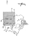
- FIG. 1 depicts the present concept for a communication system, including an earth orbiting satellite 5 , a plurality of communication regions on the earth's surface called cells 10 , a plurality of communication terminals 25 distributed among the cells, and a ground control terminal 30 .
- the cells collectively form a service area 15 .
- Satellite 5 includes a beam forming unit 45 that enables phased antenna array 20 to form separate beams of radio frequency energy for each cell in the service area.
- the communication terminals 25 which are randomly distributed throughout the service area, allow users of the system to transmit information to and receive information from satellite 5 .
- Satellite 5 communicates with communication terminals 25 over assigned radio frequency channels.
- a ground control terminal 30 which may or may not be located within the service area, provides a means to control satellite 5 and includes channel allocation unit 40 .
- Channel allocation unit 40 is shown on the ground but it may also be included up in earth orbiting satellite 5 .
- FIG. 2 illustrates the compliment of equipment contained in satellite 5 necessary to provide communication service to communication terminals 25 .
- This includes transponder 35 , beam forming unit 45 , phased array antenna 20 , and ground interface unit 50 .
- Transponder 35 comprises a plurality of transceivers. The number of transceivers provided by transponder 35 determines the number of simultaneous users that can be present in a single cell. Transponder 35 communicates with beam forming unit 45 . Beam forming unit 45 induces phase and amplitude perturbations into the signal it receives from transponder 35 . These phase and amplitude perturbations, which are based on coefficients received from the ground via ground interface unit 50 , enable phased antenna array 20 to form separate directional beams 55 for each cell in the service area. Each of said beams is aimed at a corresponding cell in the service area.
- Communication terminals 25A and 25B can be cellular telephones within the service area that can migrate from one cell to the next. Whenever a communication terminal is operating in service area 15 , it sends registration messages to satellite 5 . These registration messages are processed by transponder 35 in order to ascertain the whereabouts of each active communication terminal in the system.
- the user of communication terminal 25A wants to make a phone call to a person using communication terminal 25B .
- the first user depresses a "send" key on the communication terminal.
- communication terminal 25A sends a message to satellite 5 requesting that the system establish a communication link with communication terminal 25B. This is called a call request.
- ground interface unit 50 receives beam forming coefficients from the ground via ground interface unit 50 which cause beam forming unit 45 to steer a beam to the cell where communication terminal 25A is located.
- transponder 35 receives the call request from communication terminal 25A .
- Transponder 35 requests channel allocation unit 40 , which is located on the ground, to assign a communication channel to the pending call request.
- Channel allocation unit 40 responds to the channel request by determining which communication channel should be assigned to that channel request and communicating that channel number to transponder 35 .
- Transponder 35 then establishes a communication link with requesting communication terminal 25A using the channel assigned by channel allocation unit 40 .
- transponder 35 After a communication link is established with requesting communication terminal 25A , transponder 35 determines which cell the recipient communication terminal 25B is located in. Transponder 35 does this by means of the communication terminal registration messages that it processes. These registration messages enable transponder 35 to know the whereabouts of each active communication terminal in the system. Transponder 35 then issues a second channel request to channel allocation unit 40 . Channel allocation unit 40 again determines which channel number must be used to communicate with recipient communication terminal 25B and sends that channel number to transponder 35 .
- Transponder 35 then uses the channel number received from channel allocation unit 40 to communicate with the recipient communication terminal 25B .
- the beam forming unit 45 uses a second set of coefficients to steer a second beam to the cell that communication terminal 25B is located in. This, then, completes the communication link.
- FIG. 3 is a block diagram of the channel allocation unit 40 . It preferably consists of a central processing unit 60 which executes instruction sequences stored in a program memory 65 , a working memory 70 , a satellite interface unit 75 and a programming interface 80 .
- Channel allocation unit 40 communicates with the transponder 35 , located on satellite 5 , via a radio frequency link 85 . Initialization of the channel allocation unit occurs via programming interface 80 .
- Programming interface 80 can be connected to external computers via local area network 90 . Although the interface to the channel allocation unit is depicted as a local area network, any convenient computer interface can be used.
- central processing unit 60 executes four different instruction sequences. These four instruction sequences are: cell classification 95 ; creation of a composite traffic demand pattern 100 ; suppression of the demand pattern 105 ; and creation of a preferential channel list 110 . All of these instruction sequences reside in program memory 65 . Central processing unit 60 executes instruction sequence 95 to spatially distinguish each cell in a service area 15 . After central processing unit 60 has classified each cell in the service area, it executes instruction sequence 100 to determine the number of communication channels each cell in the service area will require when the system is operating. This results in the creation of a composite demand pattern for service area 15 .
- Central processing unit 60 then executes further instruction sequences, sequence 105 and sequence 110 , to suppress the actual demand in each cell to a level that can be accommodated by the limited number of communication channels available in the system and then to associate each communication channel in the system with a particular cell type, resulting in a preferred list of channels to be assigned to a particular cell.
- channel allocation unit 40 responds to individual requests as further illustrated in FIG. 4. To do so, central processing unit 60 executes a sequence of instructions stored in program memory 65 to interrogate satellite interface 75 to determine if a channel allocation request is pending. This is accomplished by executing instruction sequence 115 . In response to the presence of a pending channel allocation request, central processing unit 60 executes instruction sequence 120 to select a channel from the preferred list of channels for the cell that is making the request and allocates the selected channel to the requesting transceiver bank. The number of the selected channel is communicated to the transponder 35 via satellite interface 75 and it's associated radio link 85 .
- central processing unit 60 establishes a numeric identifier for each cell in the service area.
- FIG. 5 illustrates how the cells may be identified by a number beginning with No. 1 through No. "n-1" and finally No. "n", inclusive.
- each cell is illustrated as a hexagon in a honeycomb pattern with the other cells.
- the cells on the earth's surface will vary in shape, being more rounded with varying degrees of overlap with or spacing from the other adjacent cells.
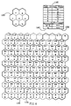
- FIG. 6 illustrates how, once each cell in the service area has been identified by a corresponding numeric identifier, central processing unit 60 uses a spatial classification pattern 125 to classify the cells in the service area.
- the pattern consists of a collection of adjacent cells; in Fig. 6, the pattern includes a center cell and each of the six immediately adjacent cells for the hexagonal cell assumption.
- the particular classification pattern used is determined by spatial restrictions to prevent interference between two cells that may be assigned the same communication channel. For instance, classification pattern 125 reflects the spatial restriction that a channel can not be used by any adjacent cell or any cell adjacent to those adjacent cells (i.e. neighbor of a neighbor). This causes classification pattern 125 to have seven distinct cell types.
- Central processing unit 60 superimposes repetitive modules of the classification pattern 125 onto all of the cells in the service area.
- the first module 130 is positioned within the service area in a random manner.
- Central processing unit 60 then superimposes successive classification pattern modules onto the remaining cells in the service area in a contiguous and non-overlapping manner.
- the second module is indicated by reference number 135 .
- Each cell within a given module is categorized according to it's position within the module; this is referred to as the cell "type".
- the lower left and right cells are respectively type “a” and "b”
- the middle left, center and right cells are type “c”
- "d” and "f” and the top left and right cells are type "f” and "g”.
- Central processing unit 60 creates memory array 140 in working memory 70 called the "primary type index".
- Memory array 140 comprises two columns of information.
- Column 145 stores the numeric identification of the cell and is called the cell ID column.
- Column 150 stores the type of the cell and is called the cell type column.
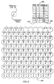
- Central processing unit 60 determines whether classification pattern 125 can be superimposed onto the cells in the service area in a different arrangement from the initial scheme; such an alternate arrangement is shown in FIG. 7. If an alternate arrangement is discovered, central processing unit 60 establishes an alternate cell classification by superimposing repetitive modules of the classification pattern 125 onto the cells in the service area in accordance with the new arrangement.
- the first module 155 of the classification pattern 125 is positioned within the service area in a random manner. Each successive module is superimposed onto the cells in a contiguous and non-overlapping manner.
- the second module of the alternative arrangement is indicated by reference number 160 .
- the first module in FIG. 6, indicated by reference number 130 and the first module in FIG. 7, indicated by reference number 155 , are selected to be coincident so that the placement of the second module relative to the first in each scheme can be contrasted.
- the first module consists of cells numbered 2, 3, 11, 12, 13, 22, and 23.
- the second module 130 consists of cells numbered 24, 25, 33, 34, 35, 44 and 45, whereas in the alternate arrangement of FIG. 7, the second module 160 is shifted one row down from FIG. 6 and consists of cells numbered 14, 15, 24, 25, 26, 34, and 35.
- Central processing unit 60 creates an array of memory elements 165 called the "secondary type index" in working memory 70 to store the alternate type for each cell based upon the alternate arrangement of FIG. 7.
- a memory array 165 (called the secondary type index) stores the numeric cell identifiers in a cell ID column 170 and the cell type, as determined by the alternate arrangement, in a cell type column 175 .
- central processing unit 60 determines the demand for communication capacity in each cell. During system initialization, central processing unit 60 executes instruction sequence 100 stored in program memory 65 to obtain numeric values representing the communication demand for each cell. The values representing communication demand are received through programming interface 80 from external computers via local area network 90 . These numeric values may represent the number of cellular telephone calls that each cell will be required to accommodate during a time interval.
- Central processing unit 60 sends the query to programming interface 80 , which in turn relays the query via the local area network 90 to external computers.
- the external computers transmit numeric values that represent the demand for communication channels in each cell in service area 15 .
- the external computers may elect one of several methods to determine the demand for communication channels in each cell. The first and most preferred method is to monitor the actual demand for communication channels within each cell in the service area and based upon these observation to calculate an average value for demand as a function of time for a particular time interval. The maximum value of this time-variant average is transmitted to channel allocation unit 40 .
- the external computers could, in one alternative, calculate a stochastic prediction for the number of communication channels each cell in the service area will require.
- Programming interface 80 receives the values from the external computers and stores these values in a buffer from which central processing unit 60 can later collect them.
- central processing unit 60 uses these numeric values to establish a composite traffic pattern 180 .
- Central processing unit 60 creates a memory array 185 , called the cell demand array, in working memory 70 .
- the cell demand array 185 consists of a cell ID column 190 and a demand column 195 which stores the numeric demand values for each cell collected from the programming interface 80 .
- the demand values shown in FIG. 8 below each cell number are for purposes of illustration only.
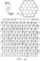
- Central processing unit 60 executes instruction sequence 105 to cause composite traffic pattern 180 and the demand values stored in memory array 185 to be suppressed.
- demand suppression is accomplished by applying a reuse zone 200 to each cell in the service area.
- the reuse zone 200 consists of a center cell together with a group of cells that are within a reuse distance from the center cell.
- the reuse distance is determined by the concentricity of the beam patterns generated by beam forming unit 45 and phased array antenna 20 .
- the antenna's radiation pattern is considered as a factor when determining the spatial separation of two cells using the same frequency.
- Reuse zone 200 is superimposed onto the cells of the service area with it's center coincident with the center of a cell in the service area.
- the reuse zone is centered on cell number 65 .
- the resultant current reuse zone 205 meaning the particular reuse zone under consideration at the moment, is then subjected to suppression.
- FIG. 10 demonstrates the mechanics of demand suppression when the reuse zone 200 is centered on cell number 65 .
- central processing unit 60 retrieves portions of primary type index 140 and cell demand array 185 that correspond to the cells included within current reuse zone 205 .
- Central processing unit 60 looks up the type of each cell in current reuse zone 205 and sorts the cells according to type to create a temporary suppression map 210 shown in FIG. 11.
- Temporary suppression map 210 tabulates which gives the cell ID numbers and corresponding channel demands for each cell type within the current reuse zone.
- Central processing unit 60 selects the maximum demand value for each cell type included within the current reuse zone 205 , and constructs a suppression table 215 in working memory 70 .
- central processing unit 60 constructs suppression table 215 in working memory 70 , the maximum demand values 220 for each cell type are summed together to yield the reuse zone's total demand 225 .
- the particular values given in the drawings are for illustration purposes only and will vary with differing initial conditions.
- Central processing unit 60 compares the total demand for the reuse zone 225 to the total number of communication channels available to the system. If the total reuse zone demand 225 is greater that the total number of available communication channels, central processing unit 60 reduces the greatest of the maximum demand values in suppression table 215 by one (1) channel, recalculates the total reuse zone demand 225 , compares the new total demand against the total number of available channels, reduces the greatest of the maximum demand values in suppression table 215 for a different cell type by one (1) channel if the total demand still exceeds the number of available channels, and continues the comparison and suppression cycles until either the total reuse zone demand 225 is less than or equal to the number of available communication channels, or each of the maximum demand values for each cell type in suppression table 215 has been reduced by one (1), or the maximum demand value for one of the cell types is equal to one (1).
- central processing unit 60 selects the greatest maximum demand value in suppression table 215 and progressively reduces it by single channel increments until either the total reuse zone demand 225 is less than or equal to the number of available channels or the maximum demand value being reduced is no longer the greatest maximum demand value in suppression table 215 . If the total reuse zone demand still exceeds the number of available channels, central processing unit 60 continues the suppression by again selecting the greatest maximum demand value in suppression table 215 and repeating the sequence until the total reuse zone demand 225 is no greater than the number of available channels.
- central processing unit 60 replaces the demand values in the cell demand array 185 with the suppressed values in suppression table 215 according to the corresponding cell type. The replacement is made only for all cells in the current reuse zone 205 , but only for those cells with demand values greater than the suppressed value. Central processing unit 60 then moves the reuse zone 200 so that it is centered on each cell in service area 15 in succession and performs the suppression process for each position of the reuse zone using the suppressed values from the previous iteration as the basis for the next cycle.
- central processing unit 60 After suppression has been accomplished for each cell in the service area, central processing unit 60 performs similar suppression for each cell in the service area using the alternate cell classification stored in the secondary type index 165 within working memory 70 .
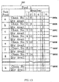
- PREFERENTIAL CHANNEL LIST After all demand suppression is complete, the demand values for each cell stored in cell demand array 185 reflect the suppressed values and not the original values collected from the external computers using programming interface 80 . Once, the demand has been suppressed, central processing unit 60 executes instruction sequence 110 to create the preferential channel list.
- the preferential channel list enumerates which channels are preferred for assignment to each cell in the system.
- the first pool represents the minimum number of channels that all cells in the system will need. This is called the base demand.
- the second demand pool represents the maximum number of channels a given type of cell will require over a particular interval of time. This is generally representative of the maximum demand each cell in the system will experience.
- the third pool caters to the extraordinary demand that systems experience during anomalous events such as conventions, rock concerts or fairs.
- central processing unit 60 creates "cell demand by type” list 230 in working memory 70 by copying the contents of the cell demand array 185 and sorting it's content according to cell type.
- the cell demand by type list 230 has cell identification column 235 , cell type column 240 and demand column 245 .
- central processing unit 60 identifies the maximum demand values 250 for each cell type. These maximum demand values will later be referred to as m a , m b , ..., m k , corresponding to the cell types "a", "b” through type “k”, where "k” is the last type of cell in any given cell classification pattern.
- Central processing unit 60 then identifies the minimum demand value from among all of the maximum demand values 250 for each type of cell.
- m e is the minimum value among all of the maximum demand values. This minimum value among all of the maximum demand values will later be referred to as "n".
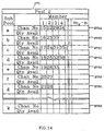
- central processing unit 60 creates a pair of two-dimensional arrays, called “pool 1" 260 and “pool 2" 270, in working memory 70 .
- Pool 1 will be used to supply the base demand profile for the cellular system while pool 2 will supply channels for the maximum demand profile.
- the two pools have respective sub-pools 265A, 265B, through 265K and 275A, 275B, through 275K with one sub-pool for each different cell type in the cell classification pattern 125 .
- Each sub-pool 265 has a number of members equal to "n"; being the minimum demand value from among all of the maximum demand values 250 for each cell type as identified from cell demand by type list 230 .
- Each sub-pool 275 has a number of members equal to the maximum demand value 250 for the corresponding cell type, referred to as, m a through m k , less the minimum value from among all of the maximum demand values in the system introduced earlier as "n".
- Pool 1 can be represented as a matrix called P1 consisting of k rows where each row has "n” members as follows: P 1[ k , n ] Where k is the number of distinct cell types in classification pattern 125 and "n" is equal to the minimum value from among all of the maximum demand values for each cell type as identified from cell demand by type list 230 ;
- Pool 2 can be represented as a matrix called P2 consisting of k rows where each row has m k members as fol-lows: P 2[ k ,( m k - n )] Where k is the number of distinct cell types in classification pattern 125 and m k is equal to the maximum demand value 250 for the corresponding cell type;
- central processing unit 60 creates a one-dimensional array of elements 280 in working memory 70 called “pool 3".
- Pool 3 has only one set of members. This set does not correspond to any particular cell type used in cell classification pattern 125 and is referred to as the "community" pool.
- the community pool is used to allocate channels that the system will use during special events when the demand for communication can not be accurately predicted.
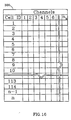
- central processing unit 60 After pools 1, 2 and 3 are created, central processing unit 60 creates a channel list 290 in working memory 70 and assigns a sequential channel number to each channel available in the system. Central processing unit 60 then allocates channels from the channel list 290 to sub-pools within pools 1 and 2.
- Channels from channel list 290 are first assigned to the sub-pools in pool 1 ( 260 ).
- central processing unit 60 assigns channels in order of the successive sub-pools 265 in pool 1 ( 260 ).
- the channel assignments proceed one channel at a time to successive sub-pools 265A , 265B , 265C through to the last subpool 265K , where K is equal to the number of types used in classification pattern 125 , and then begins again with sub-pool 265A in the member 2 column.
- the assignment of channels continues until all of the members in sub-pools 265 are populated with channel numbers from channel list 290 , or until all of the channels have been assigned, whichever comes first.
- the example of FIG. 12 assumes the system has 7 sub-pools, "a” through “g", that "n” equals 2 and there are 40 channels available, channels 1 through 14 are assigned to sub-pools 265A through 265G .
- Channels from channel list 290 are next assigned to the sub-pools in pool 2 ( 270 ). Since the number of members in each sub-pool in pool 2 ( 270 ) is variable, if a particular sub-pool in pool 2 is filled during the assignment process, it is thereafter omitted from the assignment rotation, and the assignment rotation continues until all of the members in sub-pools 275 in pool 2 ( 270 ) are populated with channel numbers from channel list 290 or until all of the channels have been assigned, whichever occurs first. Again using the example in FIG.
- channels 15 through 36 are assigned to sub-pools 275A through 275G .
- Central processing unit 60 assigns any channels that are left in channel list 290 to pool 3 ( 280 ). Given the example where only 40 channels are available, the remaining channels 37 through 40 are thus assigned to pool 3 ( 280 ).
- central processing unit 60 interrogates programming interface 80 to discover how many times each channel will be reused in the system. This is called the target reuse rate.
- the target reuse rate is then written into the quantity available elements of pool 1 ( 260 ), pool 2 ( 270 ) and pool 3 ( 280 ). The quantity available elements will then be used to track the number of times a particular channel has been allocated to the cells.
- the preferential channel list for each cell in the service area 15 is created by central processing unit 60 by drawing channel numbers from the three demand pools; the base demand pool 1 ( 260 ), the maximum demand pool 2 ( 270 ) or from community pool 3 ( 280 ).
- Central processing unit 60 maintains usage statistics for each channel in the system by incrementing a channel usage counter 295 whenever a channel is selected for assignment. Usage counter 295 is part of the channel list 290 originally introduced in FIG. 15.
- Central processing unit 60 uses the channel usage counter to determine which channels are most frequently used or which channels are least frequently used and may use these statistics as part of the channel selection criteria.
- Central processing unit 60 observes three criteria when allocating channel numbers to the individual lists that specify the preferred channels for any given cell.
- the first criteria is that a channel that is to be allocated to a cell must be statutorily allowable in that cell.
- the second criteria ensures that a channel is not already in use by a cell's neighbors. Finally, reverence is paid to the target reuse rate in order to minimize inter cell interference.
- Central processing unit 60 begins to allocate channels to those cells in the system that have the greatest demand for communication channels. These cells are known as "heavy cells”. Allocating channels to one cell at a time, central processing unit 60 attempts to select a channel from sub-pool 265 of pool 1 ( 260 ) that corresponds to the type of cell for which a channel is being selected. If corresponding sub-pool 265 in pool 1 ( 260 ) has one or more available channels, central processing unit 60 selects the most often used channel from that sub-pool.
- central processing unit 60 attempts to allocate a channel from the sub-pool 275 of pool 2 ( 270 ) that corresponds to the type of cell for which a channel is being selected. If the corresponding sub-pool 275 in pool 2 ( 270 ) has one or more available channels, central processing unit 60 selects the most often used channel from that sub-pool.
- central processing unit 60 attempts to select an available channel from community pool 3 ( 280 ).
- central processing unit 60 attempts to select a channel from pool 2 ( 270 ) from any sub-pool 275 other than the one that corresponds to the type of cell for which the channel is being selected.
- central processing unit 60 attempts to select an available channel from pool 1 ( 260 ) from any sub-pool 265 other then the one that corresponds to the type of cell for which the channel is being selected.
- pool 1 Whenever a channel from pool 1 ( 260 ), pool 2 ( 270 ) or pool 3 ( 280 ) is allocated to a cell, the quantity available element affiliated with that channel number in that particular pools is decremented by one. Once the quantity available elements has been decremented to zero (0), that channel can no longer be allocated to cells.
- central processing unit 60 allocates channels from the pools to the heavy cells, central processing unit allocates channels to the cells immediately adjacent to the heavy cells. After these neighboring cells have received channel allocation, channels are allocated to all of the remaining cells in the system.
- each cell in the system has a row of elements that store channel numbers for the corresponding cell.
- the channel numbers stored in these rows enumerate the channels that should preferably be assigned to the corresponding cell whenever a channel request is pending in that cell.
- the rows have varying numbers of channels assigned to them.
- the number of elements in each row of preferential channel list 300 is equivalent to the suppressed demand for channels in that cell as recorded in the cell demand table 185 .
- central processing unit 60 determines if a sufficient number of channels were available to satisfy the suppressed demand for each cell as dictated in cell demand array 185 . If there were not enough channels available from the pools to satisfy the demand for each cell in service area 15 , central processing unit 60 increases the target reuse rate and attempt the preferential channel allocation process anew.
- the preferential channel list for each cell 300 as formed from the various sub-pools, has an implied spatial separation of usable channels within each cell. Assigning channels from the preferential list minimizes the probability that a subsequent request for channel assignment will result in a blocked call.
- channel allocation unit 40 executes instruction sequence 120 in order to select a channel for assignment to a given cell based on that cell's identifier.
- the preferred channels are those channels listed in that cell's preferential channel list 300 .
- Non-preferred channels are those channels that are listed in the preferred channel list of that cell's immediate neighbors. All other channels are categorized with a neutral designation.
- central processing unit 60 In order to accommodate a channel request, central processing unit 60 first determines the identifier of the cell requesting a channel assignment. With this information, central processing unit 60 examines the channel number entries in preferential channel list 300 for the row that corresponds to the cell number requesting the assignment. This establishes the set of preferred channels for the assignment. Central processing unit 60 then examines the contents of the preferential channel list for all of the cell's neighbors. This establishes the set of non-preferred channels for the assignment. All other channels are then categorized as neutral. For each of these categories of channels, central processing unit 60 further distinguishes each channel according to channel assignments constraints. Hence, in each set, each channel is marked for excessive channel reuse, regulatory availability, and neighbor usage. If none of these constraints are applicable, the channel is marked as available.
- central processing unit 60 selects that channel for assignment.
- central processing unit 60 selects the channel with a reuse value less than the minimum reuse value for all the candidate channels. If there are still more than one candidate channel, central processing unit 60 selects the channel with the most beneficial weighted usefulness factor. Weighted usefulness factor is described below.
- central processing unit 60 attempts to assign a channel from the neutral set of candidates. If there is exactly one channel available from the set of neutral candidate channels, central processing unit 60 selects that channel for the assignment.
- central processing unit 60 selects the channel with a reuse value less than the minimum reuse value for all the candidate channels. If there are still more than one candidate channel, central processing unit 60 selects the channel with the most beneficial weighted usefulness factor.
- central processing unit 60 resorts to the non-preferred set of channels. If there is exactly one channel available from the set of non-preferred candidate channels, central processing unit 60 selects that channel for the assignment.
- central processing unit 60 selects the channel with a reuse value less than the minimum reuse value for all the candidate channels. If there are still more than one candidate channel, central processing unit 60 selects the channel with the most beneficial weighted usefulness factor.
- central processing unit 60 Once central processing unit 60 has selected a channel from either the preferred, neutral or non-preferred candidate sets, it communicates the channel number to transponder 35 via the channel allocation unit's satellite interface 75 .
- central processing unit 60 deassigns a dormant channel, i.e. a channel within the cell that is no longer carrying communication traffic.
- the deassignment process causes that channel to be returned to the preferential channel list 300 for that cell. Once the channel has been returned to the preferential channel list 300 , it can again be assigned to a cell as the demand for communication channels increases.
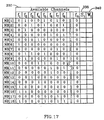
- the weighted usefulness factor measures the likelihood that any particular channel will be required by that cell's neighbors.
- the weighted usefulness factor is based on the current traffic load within the system and upon the channels that are available for use in neighboring cells.
- the number of columns in table 330 reflects the total number of channels that are eligible for allocation to each of the cells in reuse zone 200 when the center of the reuse zone is placed upon the cell needing the channel assignment. In FIG. 17, these channels are referred to as f 1 through f n .
- Central processing unit 60 examines each of the neighbors in reuse zone 200 . If a channel can be used in that cell, central processing unit 60 places a one (1) in the corresponding columns of table 330 . If the channel can not be used in that cell, central processing unit 60 places a zero (0) into that column. Once the candidacy of each channel for each cell is determined, central processing unit 60 will tally the number of channels that are available in each cell. This tally is then stored in the S i column 335 . Central processing unit 60 calculates a weight for each cell based on the number of channels that are actively being used in the cell divided by the number of channels assigned to the cell.
- the channel with the lowest calculated weighted usefulness factor is then selected for assignment in deference to those channels with higher values of weighted usefulness factor.
Landscapes
- Engineering & Computer Science (AREA)
- Computing Systems (AREA)
- Physics & Mathematics (AREA)
- Astronomy & Astrophysics (AREA)
- Aviation & Aerospace Engineering (AREA)
- General Physics & Mathematics (AREA)
- Computer Networks & Wireless Communication (AREA)
- Signal Processing (AREA)
- Mobile Radio Communication Systems (AREA)
- Radio Relay Systems (AREA)
Applications Claiming Priority (2)
| Application Number | Priority Date | Filing Date | Title |
|---|---|---|---|
| US150801 | 1998-09-10 | ||
| US09/150,801 US6269245B1 (en) | 1998-09-10 | 1998-09-10 | Cellular communication system employing dynamic preferential channel allocation |
Publications (3)
| Publication Number | Publication Date |
|---|---|
| EP0986194A2 true EP0986194A2 (de) | 2000-03-15 |
| EP0986194A3 EP0986194A3 (de) | 2003-07-09 |
| EP0986194B1 EP0986194B1 (de) | 2009-04-22 |
Family
ID=22536048
Family Applications (1)
| Application Number | Title | Priority Date | Filing Date |
|---|---|---|---|
| EP99117694A Expired - Lifetime EP0986194B1 (de) | 1998-09-10 | 1999-09-08 | Zellulare Kommunikationsanordnung mit bevorzugter dynamischer Kanal Zuteilung |
Country Status (3)
| Country | Link |
|---|---|
| US (1) | US6269245B1 (de) |
| EP (1) | EP0986194B1 (de) |
| DE (1) | DE69940758D1 (de) |
Cited By (2)
| Publication number | Priority date | Publication date | Assignee | Title |
|---|---|---|---|---|
| WO2003069936A1 (en) * | 2002-02-15 | 2003-08-21 | Inmarsat Ltd. | Carrier allocation |
| EP2086256A1 (de) | 2008-01-30 | 2009-08-05 | Deutsche Telekom AG | Verfahren zum optimierten Zuteilen von Ressourcenanforderungen an eine Vielzahl von Zellen eines zellularen Netzes |
Families Citing this family (13)
| Publication number | Priority date | Publication date | Assignee | Title |
|---|---|---|---|---|
| US6584084B1 (en) * | 1999-03-01 | 2003-06-24 | Nortel Networks Ltd. | Expanded carrier capacity in a mobile communications system |
| US7024190B1 (en) * | 2000-03-02 | 2006-04-04 | Orbcomm Llc | Method of random access communication using subbanding and variable length messages |
| US6959168B2 (en) | 2001-05-02 | 2005-10-25 | The Boeing Company | Ground control of forward link assignments |
| US8195172B2 (en) * | 2002-04-03 | 2012-06-05 | Illinois Institute Of Technology | Process to allocate channels in a sectorized and tiered cellular network |
| US8165591B2 (en) * | 2002-04-03 | 2012-04-24 | Illinois Institute Of Technology | Process to allocate channels in a sectorized cellular network |
| EP1566071B1 (de) * | 2002-10-30 | 2007-11-28 | Research In Motion Limited | Verfahren und gerät zur bevorzugten auswahl eines kommunikationsnetzes, das datendienste verfügbar macht |
| JP4358271B2 (ja) * | 2004-03-05 | 2009-11-04 | サムスン エレクトロニクス カンパニー リミテッド | 多重搬送波を用いる広帯域無線通信システムにおける副搬送波割り当て方法及び装置 |
| KR100929073B1 (ko) * | 2005-10-14 | 2009-11-30 | 삼성전자주식회사 | 휴대 방송 시스템에서 다중 스트림 수신 장치 및 방법 |
| US20080214199A1 (en) * | 2005-11-10 | 2008-09-04 | Baowei Ji | Dynamic frequency selection based on spectrum etiquette |
| US8219092B2 (en) * | 2006-10-02 | 2012-07-10 | Freescale Semiconductor, Inc. | User equipment frequency allocation methods and apparatus |
| US9715609B1 (en) * | 2013-03-11 | 2017-07-25 | The United States Of America As Represented By The Administrator Of The National Aeronautics And Space Administration | Systems, apparatuses and methods for beamforming RFID tags |
| EP3097710B1 (de) * | 2014-01-20 | 2019-02-13 | Nokia Solutions and Networks Oy | Zuweisung von wiederverwendungscodes in einem kommunikationsnetz |
| CN116388832B (zh) * | 2022-11-28 | 2025-02-25 | 北京邮电大学 | 低轨卫星捷变波束多普勒频偏估计策略选取方法及装置 |
Family Cites Families (7)
| Publication number | Priority date | Publication date | Assignee | Title |
|---|---|---|---|---|
| US5448621A (en) * | 1993-08-02 | 1995-09-05 | Motorola, Inc. | Dynamic reallocation of spectral capacity in cellular communication systems |
| US5826189A (en) * | 1994-06-13 | 1998-10-20 | Motorola, Inc. | Cellular communication system with efficient channel assignments and method therefor |
| US5732353A (en) * | 1995-04-07 | 1998-03-24 | Ericsson Inc. | Automatic control channel planning in adaptive channel allocation systems |
| US5749044A (en) * | 1995-07-14 | 1998-05-05 | Motorola, Inc. | Centralized dynamic channel assignment controller and methods |
| US5926762A (en) * | 1996-05-17 | 1999-07-20 | Internet Mobility Corporation | Cellular telephone interference prediction and frequency reuse planning |
| US5898681A (en) * | 1996-09-30 | 1999-04-27 | Amse Subsidiary Corporation | Methods of load balancing and controlling congestion in a combined frequency division and time division multiple access communication system using intelligent login procedures and mobile terminal move commands |
| US5974324A (en) * | 1997-02-10 | 1999-10-26 | Ericsson Inc. | Adaptive frequency reuse plan |
-
1998
- 1998-09-10 US US09/150,801 patent/US6269245B1/en not_active Expired - Lifetime
-
1999
- 1999-09-08 EP EP99117694A patent/EP0986194B1/de not_active Expired - Lifetime
- 1999-09-08 DE DE69940758T patent/DE69940758D1/de not_active Expired - Lifetime
Cited By (2)
| Publication number | Priority date | Publication date | Assignee | Title |
|---|---|---|---|---|
| WO2003069936A1 (en) * | 2002-02-15 | 2003-08-21 | Inmarsat Ltd. | Carrier allocation |
| EP2086256A1 (de) | 2008-01-30 | 2009-08-05 | Deutsche Telekom AG | Verfahren zum optimierten Zuteilen von Ressourcenanforderungen an eine Vielzahl von Zellen eines zellularen Netzes |
Also Published As
| Publication number | Publication date |
|---|---|
| EP0986194B1 (de) | 2009-04-22 |
| EP0986194A3 (de) | 2003-07-09 |
| DE69940758D1 (de) | 2009-06-04 |
| US6269245B1 (en) | 2001-07-31 |
Similar Documents
| Publication | Publication Date | Title |
|---|---|---|
| EP0986194B1 (de) | Zellulare Kommunikationsanordnung mit bevorzugter dynamischer Kanal Zuteilung | |
| US5839074A (en) | Process of allocating frequencies to base stations of a mobile radiotelephone network | |
| US5428815A (en) | Communication system with geographic reuse dynamically sensitive to communication unit type | |
| US6549782B2 (en) | Radio communications systems | |
| AU750721B2 (en) | Adaptive frequency reuse plan | |
| US5749044A (en) | Centralized dynamic channel assignment controller and methods | |
| US6597913B2 (en) | Distributed dynamic channel management in cellular systems | |
| US7945269B2 (en) | Method of carrier allocation to a plurality of cells in a cellular communication system | |
| US5507007A (en) | Method of distributing capacity in a radio cell system | |
| US5926763A (en) | Cellular communication system with voice channel usage biasing | |
| EP0825794A2 (de) | Netzflusssteuerungsstruktur für on-line dynamische Kanalverteilung | |
| JPH04302547A (ja) | セル方式無線電話システムにおけるチャンネル割当方法及び同システム | |
| CN101375620B (zh) | 用于在通信系统中适应性分配唯一字的系统和方法 | |
| CN1120766A (zh) | 基于位置访问的通信系统 | |
| CN1164170A (zh) | 空分多址无线电通信系统及其内分配信道的方法 | |
| CN1265814A (zh) | 通信系统里的特制分级小区结构 | |
| US6539228B1 (en) | Channel allocation in cellular telephony | |
| US6385188B1 (en) | Method for sharing channels between base station sectors and frequency assignments in code division multiple access system | |
| CA2192248A1 (en) | Method and apparatus for spectrum management | |
| EP1040693A1 (de) | Verfahren zur interferenzvorhersage in einem zellularen kommunikationssystem mit frequenzsprung | |
| KR100373444B1 (ko) | 무선 주파수망 구성 시스템 및 그 구동 방법 | |
| EP0610645B1 (de) | Verfahren zur Verteilung von Kanalkapazität in einem Zellularsystem | |
| Wu et al. | Optimized hybrid resource allocation in wireless cellular networks with and without channel reassignment | |
| Zhang et al. | A nominal channel allocation algorithm for cellular mobile systems | |
| CA2334447C (en) | Coordinated satellite-terrestrial frequency reuse |
Legal Events
| Date | Code | Title | Description |
|---|---|---|---|
| PUAI | Public reference made under article 153(3) epc to a published international application that has entered the european phase |
Free format text: ORIGINAL CODE: 0009012 |
|
| AK | Designated contracting states |
Kind code of ref document: A2 Designated state(s): AT BE CH CY DE DK ES FI FR GB GR IE IT LI LU MC NL PT SE |
|
| AX | Request for extension of the european patent |
Free format text: AL;LT;LV;MK;RO;SI |
|
| PUAL | Search report despatched |
Free format text: ORIGINAL CODE: 0009013 |
|
| AK | Designated contracting states |
Designated state(s): AT BE CH CY DE DK ES FI FR GB GR IE IT LI LU MC NL PT SE |
|
| AX | Request for extension of the european patent |
Extension state: AL LT LV MK RO SI |
|
| 17P | Request for examination filed |
Effective date: 20030802 |
|
| AKX | Designation fees paid |
Designated state(s): DE FR GB IT |
|
| 17Q | First examination report despatched |
Effective date: 20070829 |
|
| GRAP | Despatch of communication of intention to grant a patent |
Free format text: ORIGINAL CODE: EPIDOSNIGR1 |
|
| GRAS | Grant fee paid |
Free format text: ORIGINAL CODE: EPIDOSNIGR3 |
|
| GRAA | (expected) grant |
Free format text: ORIGINAL CODE: 0009210 |
|
| AK | Designated contracting states |
Kind code of ref document: B1 Designated state(s): DE FR GB IT |
|
| REG | Reference to a national code |
Ref country code: GB Ref legal event code: FG4D |
|
| REF | Corresponds to: |
Ref document number: 69940758 Country of ref document: DE Date of ref document: 20090604 Kind code of ref document: P |
|
| PLBE | No opposition filed within time limit |
Free format text: ORIGINAL CODE: 0009261 |
|
| STAA | Information on the status of an ep patent application or granted ep patent |
Free format text: STATUS: NO OPPOSITION FILED WITHIN TIME LIMIT |
|
| 26N | No opposition filed |
Effective date: 20100125 |
|
| REG | Reference to a national code |
Ref country code: FR Ref legal event code: PLFP Year of fee payment: 18 |
|
| REG | Reference to a national code |
Ref country code: FR Ref legal event code: PLFP Year of fee payment: 19 |
|
| REG | Reference to a national code |
Ref country code: FR Ref legal event code: PLFP Year of fee payment: 20 |
|
| PGFP | Annual fee paid to national office [announced via postgrant information from national office to epo] |
Ref country code: IT Payment date: 20180919 Year of fee payment: 20 Ref country code: DE Payment date: 20180815 Year of fee payment: 20 Ref country code: FR Payment date: 20180817 Year of fee payment: 20 |
|
| PGFP | Annual fee paid to national office [announced via postgrant information from national office to epo] |
Ref country code: GB Payment date: 20180828 Year of fee payment: 20 |
|
| REG | Reference to a national code |
Ref country code: DE Ref legal event code: R071 Ref document number: 69940758 Country of ref document: DE |
|
| REG | Reference to a national code |
Ref country code: GB Ref legal event code: PE20 Expiry date: 20190907 |
|
| PG25 | Lapsed in a contracting state [announced via postgrant information from national office to epo] |
Ref country code: GB Free format text: LAPSE BECAUSE OF EXPIRATION OF PROTECTION Effective date: 20190907 |